Sign In
Upload
Download
Table of Contents
Contents
Add to my manuals
Delete from my manuals
Share
URL of this page:
HTML Link:
Bookmark this page
Add
Manual will be automatically added to "My Manuals"
Print this page
×
Bookmark added
×
Added to my manuals
Manuals
Brands
Titan Manuals
Lawn Mower
FLAIL Series
Operator's manual
Titan FLAIL Series Operator's Manual
Hide thumbs
1
2
3
4
5
6
7
8
9
10
11
12
13
14
15
16
17
18
19
20
21
22
23
24
Table Of Contents
25
page
of
25
Go
/
25
Contents
Table of Contents
Troubleshooting
Bookmarks
Table of Contents
Important Safety Information
For Your Protection
Shutdown and Storage
Prepare for Emergencies
Tire Safety
Safety Labels
Section 1: Assembly and Set-Up
Tractor Requirements
Packing List
Tools Required
Tractor Hook-Up
Tractor Shut down Procedure
Mowing Instructions
Section 3: Adjustments
Leveling the Mower
Cutting Height Adjustment
Belt Tension
Section 4: Maintenance
Knife Replacement
V-Belt Installation
Section 6: Troubleshooting
Bolt Torque
Advertisement
Quick Links
1
Section 1: Assembly and Set-Up
2
Tractor Requirements
3
Tractor Hook-Up
4
Cutting Height Adjustment
5
Belt Tension
6
Section 4: Maintenance
7
V-Belt Installation
8
Section 6: Troubleshooting
Download this manual
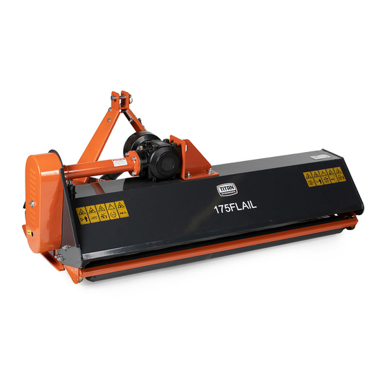
FLAIL SERIES
155FLAIL, 175FLAIL, 185FLAIL
191522,191523,191524
Operator's Manual
Read the Operator's Manual entirely. When you see this
symbol, the subsequent instructions and warnings are
serious follow without exception. Your life and the lives
of others depend on it!
Table of
Contents
Previous
Page
Next
Page
1
2
3
4
5
Advertisement
Table of Contents
Need help?
Do you have a question about the FLAIL Series and is the answer not in the manual?
Ask a question
Questions and answers
Related Manuals for Titan FLAIL Series
Lawn Mower Titan TTT837LWM Original Instructions Manual
Cordless lawnmower 36v 37cm (40 pages)
Lawn Mower Titan TTLMP300SP40 Manual
(28 pages)
Lawn Mower Titan 3515 Operation And Parts Manual
Flex-wing rotary cutter (78 pages)
Lawn Mower Titan TTK550LWM Owner's Manual
Ride-on mower (43 pages)
Lawn Mower Titan 125FLAILDB Operator's Manual
Flail ditch bank mowers (27 pages)
Lawn Mower Titan 125FLAILSHFT Operator's Manual
Flail side shift mower (26 pages)
Lawn Mower Titan TTI836LWM Manual
Lawnmower 18v 34cm (40 pages)
Lawn Mower Titan TTT838LWM Getting Started
Cordless lawnmower 36v 41cm (40 pages)
This manual is also suitable for:
155flail
175flail
185flail
191522
191523
191524
Table of Contents
Save PDF
Print
Rename the bookmark
Delete bookmark?
Delete from my manuals?
Login
Sign In
OR
Sign in with Facebook
Sign in with Google
Upload manual
Upload from disk
Upload from URL


Need help?
Do you have a question about the FLAIL Series and is the answer not in the manual?
Questions and answers