Table of Contents
Advertisement
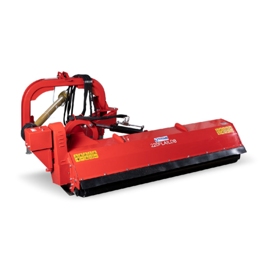
FLAIL DITCH BANK
125FLAILDB, 145FLAILDB, 165FLAILDB, 200FLAILDB,
220FLAILDB
191519, 191520, 191521, 191525, 191526
MOWERS
Operator's Manual
Read the Operator's Manual entirely. When you see this
symbol, the subsequent instructions and warnings are
serious follow without exception. Your life and the lives
of others depend on it!
Advertisement
Table of Contents

Related Manuals for Titan 125FLAILDB


Summary of Contents for Titan 125FLAILDB
- Page 1 FLAIL DITCH BANK MOWERS 125FLAILDB, 145FLAILDB, 165FLAILDB, 200FLAILDB, 220FLAILDB 191519, 191520, 191521, 191525, 191526 Operator’s Manual Read the Operator’s Manual entirely. When you see this symbol, the subsequent instructions and warnings are serious follow without exception. Your life and the lives...
-
Page 2: Important Safety Information
IMPORTANT NOTE BEFORE USE ADD SAE 90 GEAR OIL. DO NOT OVERFLOW. SEE PAGE 17. • • Ensure roller weldment is adjusted to proper setting before first use. Do not engage PTO while adjusting the offset of the mower. • IMPORTANT SAFETY INFORMATION THESE ARE STANDARD PRACTICES THAT MAY NOT APPLY TO THE PRODUCTS DESCRIBED IN THIS MANUAL. -
Page 3: For Your Protection
BE AWARE OF SAFETY ALERT WORDS DANGER: Indicates imminently hazardous practices. A situation that, if not avoided, will result in death or severe injury. The signal word is limited to the most extreme situation, typically for machine components that, for functional purposes, cannot be guarded. WARNING: Indicates a potentially hazardous situation that, if not avoided, could result in death or severe injury, and includes hazards that are exposed when guards remove. -
Page 4: Prepare For Emergencies
Operator’s Manual for additional information. Work in a clean, dry area • Lower the implement to the ground, put the tractor in park, turn off the engine, and • remove the key before maintenance. Allow implement to cool completely. • Do not grease or oil implement while it is in operation. -
Page 5: Safety Labels
SAFETY LABELS Your flail Mower comes equipped with all safety labels in place. They were designed to help your safety operate your implement. Read and follow their directions. -
Page 6: Tractor Requirements
INTRODUCTION APPLICATION The Flail Mowers are designed for Category 1, Three-Point Hitch Mounting. These fixed bar Flail Mowers are ideal for ripping, leveling, finish grading, and backfilling applications at outdoor arenas, building sites, and farm and ranch lanes or roadways maintenance operations. SECTIONS 1: ASSEMBLY AND SET-UP TRACTOR REQUIREMENTS This mower is designed with a Category 1, 3 Point Hitch. -
Page 7: Packaging List
PACKAGING LIST THE DETAILED PACKING LIST OF THE MOWER AND ACCESSORY AS THE FOLLOWING TABLE 1. 1-1: Table Packing List of The Mower and Accessory THE DETAILED DESCRIPTION OF MAIN BODY OF THE MOWER FITTINGS Figure 1-3: Main Body of The Mower and Fittings Table 1-3: Main Body of The Mower and Fittings List... - Page 8 THE DETAILED DESCRIPTION OF SWING ARMS SUB-ASSEMBLY AND FITTINGS Figure 1-4: Swing Arms Sub-Assembly and Fittings Table 1-4: Swing Arms Sub-Assembly and Fittings List THE DETAILED DESCRIPTION OF HITCH TUBE WELDMENT AND FITTINGS Figure 1-5: Hitch Tube Weldment and Fittings Table 1-5: Hitch Tube Weldment and Fittings List...
- Page 9 THE DETAILED DESCRIPTION OF BOOT SUB-ASSEMBLY Figure 1-6: Boot Sub-Assembly Table 1-6: Boot Sub-Assembly List...
-
Page 10: Tools Required
ASSEMBLY INSTRUCTIONS The assembly instruction will guide you to finish the final assembly of your new mower easily. TOOLS REQUIRED Wrench with 36mm sleeve and 46mm sleeve. • TORQUE APPLICATION Refer to bolt torque in Appendix. • ASSEMBLY STEP 1: ADJUSTING OVERTURNING BRACKET WELDMENT ON MAIN BODY OF THE MOWER 1. - Page 11 STEP 2: INSTALLING SWING ARMS SUB-ASSEMBLY 1. Remove the packaging of Swing Arm Sub-Assembly and fittings. 2. Push swing arms sub-assembly into the overturning bracket weldment as shown in Figure 1-7. 3. Fix it with 1pc SWING ARM PIN-SHORTER, 1pc SWING ARM PIN-LONGER, 2pc PLAIN WASHERS 30 and 2pc LOCKNUTS M30.
-
Page 12: Tractor Hook-Up
1. The safety pin of hitch weldment is designed to limit the rotation of hitch tube weldment around the screw M24x140. 2. Remove and insert the safety pin into the left hole on the lifting bracket weldment of swing arms sub-assembly before operation. 3. -
Page 13: Section 2: Operating Instructions
SECTION 2: OPERATING INSTRUCTIONS TRACTOR SHUT DOWN PROCEDURE It is essential that the tractor be shut down as noted below before making inspection, maintenance and /or repairs to the tractor and/or mower. 1. Park tractor on a level ground. Don’t Park the implement on a steep incline. 2. -
Page 14: Section 3: Adjustments
7. Lower mower to ground. Set tractor throttle at approximately ¼ open. Engage PTO to start blades rotating. 8. Operate with 540 rpm PTO tractor. 9. At first begin mowing at a slow forward speed and shift up until the desired speed is achieved maintaining 540 rpm PTO 10. -
Page 15: Belt Tension
BELT TENSION CAUTION Excessive tension on the belt may lead to premature failure of belt and drive components. Excessive tension on the belt may also lead to a safety hazard to the operator or bystanders. The belt tension should be checked after the first 20 hours of use. And then every 40 hours of use. -
Page 16: V-Belt Installation
Figure 4-1: Hammer Blade Replacement Figure 4-2: Y-Type Blade Replacement 1. Remove locknut (#1), bolt (#3) for hammer blade or bolt (#1), spacer (#2), locknut (#4) for Y-type blade. 2. Replace new hammer blade or Y-type blade and reinstall bolt & locknut as well as retighten it. - Page 17 GEARBOX...
- Page 18 SECTION 5: SPECIFICATION & CAPACITIES SECTION 6: TROUBLESHOOTING...
- Page 20 BOLT TORQUE The tables shown below give correct torque values for various bolts and cap screws. Tighten all bolts to the torques specified unless otherwise noted. Check tightness of bolts periodically, using bolt torque chart as a guide. Replace hardware with the same strength bolt.
- Page 21 PARTS DIAGRAM/EXPLODED VIEW...
- Page 25 Titan, its insurers, employees, officers, directors, associates, and agents from any and all claims, demands, damages, rights of action, or causes of action, present or future, whether the same be known or unknown, anticipated, or unanticipated, resulting from or arising out of the use of said equipment.
- Page 26 NEED HELP? CONTACT US FIRST. 1-800-605-7595 info@palletworks.com www.palletforks.com © 2021 Titan Brands...
Need help?
Do you have a question about the 125FLAILDB and is the answer not in the manual?
Questions and answers
I have a flail145db and need the drive belts, where can I find them?