
Related Manuals for Nakanishi AL-A1205


Summary of Contents for Nakanishi AL-A1205
- Page 1 エアーラインキット / Air Line Kit AL - A1205 取 扱 説 明 書 / OPERATION MANUAL 日本語:P1 - P7 / English:P9 - P15 OM-K0654...
-
Page 2: Cautions For Handling And Operation
Thank you for purchasing " AL - 1205 " Air Line Kit. This Air Line Kit will supply clean and dry cooling air to the Air Bearing Spindle and Turbine Motor. THIS AIR LINE KIT IS NOT A SUBSTITUTE FOR AN AIR DRYER. Read this and all the associated component Operation Manuals carefully before use. - Page 3 CAUTION ① Use of dry air Using compressed air containing excessive moisture could result in malfunction or failure of the air bearing spindle. If excessive moisture or condensation are found in Oil Mist Filter Bowl, it will be necessary to install a dryer and larger Air Filter on the primary side of the Air Line Kit to prevent and remove excessive moisture.
-
Page 4: Specifications
3 . SPECIFICATIONS Model AL - A1205 Primary Air Pressure Less than 1.0MPa Secondary Air Pressure Less than 0.85MPa Maximum Operation Pressure 1.0MPa Maximum Peak Pressure Less than 1.5MPa Maximum Peak Pressure at Hose Connection Less than 1.0MPa Filtration of the Oil Mist Filter 0.3μm Primary Side Air Pressure: 0.7MPa Maximum Air Volume Allowed... -
Page 5: Parts Names
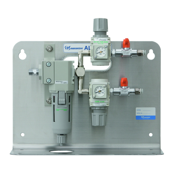
4 . PARTS NAMES ② Regulator Pressure Gauge ① Oil Mist Filter ON / OFF Valve Connection Hose Secondary Joint 6 One - Touch Joint Primary Joint Connector for Air Hose Bowl ③ Regulator Regulator Knob Fig. 1 If the Oil Mist Filter or Regulator are damaged, all components are replacable by the end-user. (Refer to Table 1 and Table 2). -
Page 6: Operation
5 . OPERATION 5 - 1 Oil Mist Filter (Fig. 2) The water, oil, dirt and debris are separated from the compressed air. The separated debris is collected in the Bowl. 5 - 2 Draining (Fig. 2) Upper Limit Opening and closing the Drain Valve. (DO NOT allow liquids and / or debris to exceed the Upper Bowl Limit as shown in Fig. - Page 7 6 . INSTALLATION AND CONNECTION OF THE AIR LINE KIT CAUTION The Air Line Kit install to the horizontal. If " Rear Mounting ", install the Air Line Kit to the horizontally on a vertical wall. 6 - 1 Installation of the Air Line Kit (1) Horizontal Installation When the Air Line Kit is mounted from the bottom in a horizontal position Af x the Rubber Pads (Standard Accessories : 4pcs.) to the bottom of the Air Line Kit.
-
Page 8: Troubleshooting
7 . TROUBLESHOOTING If a problem or concern occur, please check the following items prior to consulting your dealer. Trouble Inspection / Corrective Active Broken connection hose and supply Replace the connection hose and supply air hose. air hose. No air ow. Check the compressor power supply and the air compressor output. - Page 9 2013.04.20 002...
Need help?
Do you have a question about the AL-A1205 and is the answer not in the manual?
Questions and answers