Table of Contents
Advertisement
Available languages
Available languages
FCC-B Radio Frequency Interference Statement
This equipment has been tested and found to comply with the limits for a class B digital device, pursuant to part 15 of
the FCC rules. These limits are designed to provide reasonable protection against harmful interference when the
equipment is operated in a commercial environment. This equipment generates, uses and can radiate radio frequency
energy and, if not installed and used in accordance with the instruction manual, may cause harmful interference to
radio communications. Operation of this equipment in a residential area is likely to cause harmful interference, in
which case the user will be required to correct the interference at his own expense.
Notice 1
The changes or modifications not expressly approved by the party responsible for compliance could void the user's
authority to operate the equipment.
Notice 2
Shielded interface cables and A.C. power cord, if any, must be used in order to comply with the emission limits.
VOIR LA NOTICE D'NSTALLATION AVANT DE RACCORDER AU RESEAU.
This device complies with Part 15 of the FCC Rules. Operation is subject to the following two conditions:
(1) this device may not cause harmful interference, and
(2) this device must accept any interference received, including interference that may cause undesired operation
Micro-Star International
MS-6788
G52-M6788XA
i
Advertisement
Table of Contents

Related Manuals for MSI 848P Neo-V Series


Summary of Contents for MSI 848P Neo-V Series
- Page 1 FCC-B Radio Frequency Interference Statement This equipment has been tested and found to comply with the limits for a class B digital device, pursuant to part 15 of the FCC rules. These limits are designed to provide reasonable protection against harmful interference when the equipment is operated in a commercial environment.
-
Page 2: Copyright Notice
Copyright Notice The material in this document is the intellectual property of MICRO-STAR INTERNATIONAL. We take every care in the preparation of this document, but no guarantee is given as to the correctness of its contents. Our products are under continual improvement and we reserve the right to make changes without notice. Trademarks All trademarks are the properties of their respective owners. -
Page 3: Safety Instructions
Safety Instructions 1. Always read the safety instructions carefully. 2. Keep this User Manual for future reference. 3. Keep this equipment away from humidity. 4. Lay this equipment on a reliable flat surface before setting it up. 5. The openings on the enclosure are for air convection hence protects the equipment from overheating. Do not cover the openings. - Page 4 Table of Content English...1 Deutsch...15 Français...31 简体中文 ...45 繁體中文 ...59 Nederlands ...73 日本語...89...
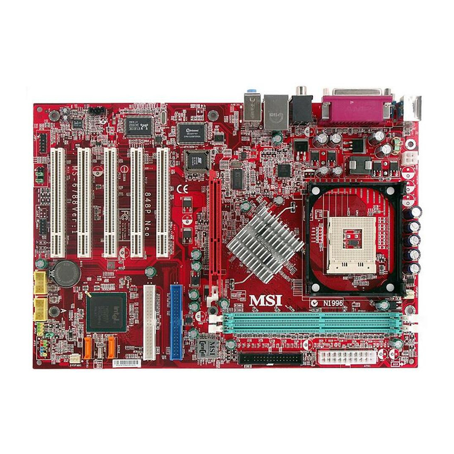
- Page 5 Neo-V/865PE Neo2-V Series is based on Intel® 848P/865PE & ICH5 chipsets for optimal system efficiency. Designed to fit the advanced Intel ® Pentium ® 4 processors in 478 pin package, the 848P Neo-V/865 PE Neo2-V Series delivers a high performance and professional desktop platform solution.
-
Page 6: Agp Slot
JS P1 CP UFAN1 ATX Power Supply In tel 84 8P chi pset AGP Slot IDE 2 IDE 1 BATT US B2 JD B1 848P Neo-V S ATA2 ICH 5 SATA1 SYSFAN 1 FDD1 JB AT1 JFP1 U SB 3 JFP2... -
Page 7: Specifications
FSB 400MHz (for Northwood only) / 533MHz / 800MHz depending on the North Bridge integrated. Supports up to 3.4GHz or higher speed P4 processor. (For the latest information about CPU, please visit http://www.msi.com.tw/program/products/mainboard/mbd/pro_mbd_cpu_support.php) Chipset Intel® 865PE / 848P chipset - Supports 400/533/800MHz Intel NetBurst micro-architecture bus. - Page 8 On-Board IDE Dual Ultra DMA 66/100 IDE controllers integrated in ICH5. - Supports PIO, Bus Master operation modes and can connect up to four Ultra ATA drives. Serial ATA/150 controller integrated in ICH5. - Up to 150MB/sec transfer rate and can connect up to 2 Serial ATA drives. On-Board Peripherals On-Board Peripherals includes.
-
Page 9: Hardware Setup
If you do not have the heat sink and cooling fan, contact your dealer to purchase and install them before turning on the computer. (For the latest information about CPU, please visit http://www.msi.com.tw/program/products/mainboard/mbd/pro_mbd_cpu_support.php) Example of CPU Core Speed Derivation Procedure CPU Clock... -
Page 10: Cpu Installation Procedures For Socket 478
To dissipate heat, you need to attach the CPU cooling fan and heatsink on top of the CPU. Follow the instructions below to install the Heatsink/Fan: Locate the CPU and its retention mechanism on the motherboard. Position the heatsink onto the retention mechanism. -
Page 11: Power Supply
2 GB/3GB without ECC. You can install DDR266/DDR333/DDR400 DDR SDRAM modules on the DDR DIMM slots. To operate properly, at least one DIMM module must be installed. (For the updated supporting memory modules, please visit http://www.msi.com.tw/program/products/mainboard/mbd/pro_mbd_trp_list.php.) The DDR DIMM has only one notch on the center of module. -
Page 12: Fan Power Connectors: Cpufan1/Sysfan1
GND. If the mainboard has a System Hardware Monitor chipset on-board, you must use a specially designed fan with speed sensor to take advantage of the CPU fan control. MSI Reminds You... 1. Always consult the vendors for proper CPU cooling fan. -
Page 13: Front Panel Audio Connector: Jaud1
The front panel audio connector allows you to connect to the front panel audio and is compliant with Intel ® Front Panel I/O Connectivity Design Guide. MSI Reminds You... Not to connect to the front audio header, pins 5 & 6, 9 & 10 should jumper in order to have signal output directed to the rear audio ports. -
Page 14: D-Bracket™2 Connector: Jdb1 (Optional)
MSI Reminds You... Please do not fold the Serial ATA cable into 90-degree angle. Otherwise, the loss of data may occur during transmission. D-Bracket™2 Connector: JDB1 (Optional) The mainboard comes with a JDB1 connector for you to connect to D-Bracket™2. -
Page 15: Bios Setup
BIOS Setup Power on the computer and the system will start POST (Power On Self Test) process. When the message below appears on the screen, press <DEL> key to enter Setup. DEL: Setup F11: Boot Menu F12: Network boot TAB: Logo … If the message disappears before you respond and you still wish to enter Setup, restart the system by turning it OFF and On or pressing the RESET button. -
Page 16: Frequency/Voltage Control
CoreCellTM Technology. It is designed to detect the load balance of CPU while running programs, and to adjust the best CPU frequency automatically. When the motherboard detects CPU is running programs, it will speed up CPU automatically to make the program run smoothly and faster. - Page 17 CPU Ratio Selection This setting controls the multiplier that is used to determine the internal clock speed of the processor relative to the external or motherboard clock speed. DRAM Frequency Use this field to configure the clock frequency of the installed DRAM. Settings are:...
- Page 18 CPU Vcore The setting is adjustable if you set the CPU Vcore Adjust to [Yes] . MSI Reminds You... Changing CPU Ratio/Vcore could result in the instability of the system; therefore, it is NOT recommended to change the default setting for long-term usage.
- Page 19 Einleitung Vielen Dank für den Kauf 848P Neo-V/865PE Neo2-V (MS-6788 v2.X) Serie ATX Mainboard. Die 848P Neo-V/865PE Neo2-V Serie sind Mainboards basiert auf Intel® 848P/865PE & ICH5 Chipsatz für optimale Systemeffizienz. Entwickelt, für den für fortschrittlichen Intel ® Pentium ® 4 Prozessor im 478 Pin Ge- häuse, liefert 848P Neo-V/865 PE Neo2-V Series hohe Perfomance für eine proffessionelle Desktop-PC...
- Page 20 JS P1 CP UFAN1 ATX Power Supply In tel 84 8P chi pset AGP Slot ICH 5 IDE 2 IDE 1 BATT US B2 U SB 3 JD B1 848P Neo-V S ATA2 SATA1 SYSFAN 1 FDD1 JB AT1 JFP1 JFP2...
-
Page 21: Spezifikationen
FSB 400 (nur für Northwood), 533, 800 (nur für PT880/PT800 only) MHz Unterstützt bis 3.4GHz oder schneller (Für die neuesten CPU-Kompatiblitäts-Informationen besuchen Sie bitte die folgende Webseite: http://www.msi.com.tw/program/products/mainboard/mbd/pro_mbd_cpu_support.php ) Chipsatz Intel® 865PE / 848P Chipsatz - Unterstützt 400/533/800MHz Intel NetBurst Microarchitektur - Unterstützt AGP 8X/4X Schnittstelle. - Page 22 On-Board IDE Zwei Ultra DMA 66/100 IDE Kontrollers im ICH5 integriert. - Unterstützt PIO und Bus Master Modus, es können bis zu 4 IDE Laufwerke angeschlossen werden. Serial ATA/150 Kontroller im ICH5 integriert. - Bis zu 150MB/s Transferrate, es können bis zu 2 Serial ATA Laufwerke angeschlossen werden. On-Board Peripherie On-Board Peripherie beinhaltet.
-
Page 23: Anschlüsse Auf Der Rückseite
Sie Ihren Händler, um ein passendes Modell erwerben. Bitte schalten Sie den PC nicht ein, wenn Sie keinen geeigneten Kühler installiert haben. (Für die neuesten CPU-Kompatiblitäts- Informationen besuchen Sie bitte die folgende Webseite: http://www.msi.com.tw/program/products/mainboard/mbd/pro_mbd_cpu_support.php ) Beispiel für die Ermittlung des CPU-Kerntaktes Wenn... -
Page 24: Installation Des Cpu-Kühlers
CPU Installationsprozedur für Sockel 478 Bitte schalten Sie den PC aus und ziehen das Netzkabel ab, bevor Sie die CPU einsetzen. Klappen Sie den Hebel am CPU-Sockel auf. Stellen Sie sicher, dass er im 90 Grad Winkel aufgeklappt ist. Sehen Sie den goldenen Pfeil an der CPU?. Dieser Pfeil muss zum Hebelmechanismus des Sockels zeigen. - Page 25 MSI erinnert Sie... Überhitzung… Überhitzung beschädigt Ihre CPU und ds gesamte System ernsthaft, stellen Sie daher sicher, dass die Lüfter immer funktionieren, um die CPU und das System vor Schäden zu bewahren. Die CPU tauschen… Wenn Sie die CPU tauschen, schalten Sie das System ab und ziehen den Netzstecker. Bevor Sie das Mainboard oder die CPU anfassen, erden Sie sich, in dem Sie kurz geerdeten Gegenstand (z.B.
- Page 26 Da das Mainboard mit Hardware monitor ausgestattet ist, müsen Sie spezielle Lüfter mit Speed-Signal verwenden, damit die Lüftergeschwindigkeit ausgewertet und gesteuert werden kann . MSI erinnert Sie... 1. Verwenden Sie stets einen geeigneten CPU-Lüfter und beachten Sie die Einbauhinweise in diesem Handbuch und in der Lüfterdokumentation.
- Page 27 Das erste Laufwerk sollte an IDE1 angeschlossen werden. IDE1 unterstützt Master und Slave-Laufwerke. IDE2 (Sekundärer IDE Anschluss): IDE2 unterstützt Master und Slave Laufwerke. MSI erinnert Sie... Wenn Sie zwei IDE-Laufwerke an einem IDE-Kabel anschließen, so müssen Sie das erste Laufwerk als Master und das zweite Laufwerk als Slave konfigurieren.
- Page 28 CMOS-Konfiguration löschen wollen, setzen Sie im ausgeschalteten Zustand den Jumper JBAT1 von Position 1-2 auf 2-3 um. MSI erinnert Sie... Schalten Sie den PC vor dem Umsetzen des Jumpers aus. Setzen Sie den Jumper nach ein paar Sekunden wieder in 1-2 zurück und schalten erst dann den PC wieder ein.
-
Page 29: Pci Interrupt Request Routing
Sie auch die Dokumentation der Erweiterungskarte bezüglich Hinweisen des Herstellers zum Einbau und möglichen Hardware- und Softwareeinstellungen. Der orangene PCI Steckplatz (PCI5) funktioniert auch als Kommunikations-Steckplatz mit speziellen Kommunikationskarten von MSI. PCI Interrupt Request Routing The IRQ, acronym of interrupt request line and pronounced I-R-Q, are hardware lines over which devices can send interrupt signals to the microprocessor. -
Page 30: Bios Setup
BIOS Setup Wenn Sie den PC einschalten, startet er zuerst die POST-Systemdiagnose (Power On Self Test). Wenn die folgende Meldung angezeigt wird, dann drücken Sie die Taste <Entf> um in das BIOS-Setup zu gelangen. DEL: Setup F11: Boot Menu F12: Network boot TAB: Logo Wenn die Meldung verschwindet, bevor Sie die Taste gedrückt haben, wird es das installierte Betriebssystem starten. -
Page 31: Frequency/Voltage Control
Power Management Features Hier können Sie Energieoptionen einstellen. PNP/PCI Configurations Dieser Eintrag wird angezeicht, wenn Ihr System PnP/PCI unterstützt. Integrated Peripherals Hier können Sie Einstellungen zu Peripheriegerätetn vornehmen. PC Health Status Dieses Untermenü zeigt Ihnen die Hardwareüberwachung Ihres Systems an. Frequency/Voltage Control Use this menu to specify your settings für frequency/voltage control. - Page 32 Performance Mode Erlaubt es Ihnen die Funktion MAT (Memory Acceleration Technology) des Mainboards zu aktivieren. MAT ist eine exclusive Technologie von MSI zwischen CPU, Chipsatz und Speicher. MAT kann das System um bis zu 10% beschleunigen. Die Einstellung [Fast] schaltet MAT ein. Beachten Sie bitte, dass nicht jades Speichermodul mit MAT kompatibel ist.
- Page 33 CPU Vcore Diese Einstellung ist möglich, sobald Sie dievorherige Einstellung auf [Yes] gestellt haben. MSI erinnert Sie... Das Ändern des CPU Multiplikators/Taktes/Spannung kann zu einem instabilen Systemverhalten führen. Daher ist es nicht empfohlen, die Standardeinstellung für eine längere Betriebszeit zu ändern.
- Page 35 Introduction Félicitation vous venez d’acheter une carte mère ATX 848P Neo-V/865PE Neo2-V (MS-6788 v2.X). Les 848P Neo-V/865PE Neo2-V Series sont basées sur des chipsets Intel® 848P/865PE & ICH5 très performants. Destinées aux processeurs Intel ® Pentium ® 4 (socket 478), ces cartes sont parfaites pour tous les types d’applications et toutes les plateformes.
- Page 36 JS P1 CP UFAN1 ATX Power Supply In tel 84 8P chi pset AGP Slot ICH 5 IDE 2 IDE 1 BATT US B2 U SB 3 JD B1 848P Neo-V S ATA2 SATA1 SYSFAN 1 FDD1 JB AT1 JFP1 JFP2...
- Page 37 FSB 400MHz (pour Northwood uniquement) / 533MHz / 800MHz selon le North Bridge intégré. Supporte les processeurs jusqu’à 3.4GHz ou supérieur. (Pour plus d’informations sur le CPU, veuillez visiter notre site web à cette adresse http://www.msi.com.tw/program/products/mainboard/mbd/pro_mbd_cpu_support.php) Chipset chipset Intel® 865PE / 848P - Supporte la micro architecture Intel 400/533/800MHz.
- Page 38 - Supporte les modes opératoires PIO, Bus Master. Possibilité de connecter jusqu’à quatre matériels Ultra ATA. Contrôleur Serial ATA/150 intégré dans l’ICH5. - Taux de transfert allant jusqu’à 150MB/sec, possibilité de connecter 2 disques Serial ATA. Périphériques Intégrés Les périphériques intégrés sont : - 1 port floppy supportant 1 FDD (360K, 720K, 1.2M, 1.44M et 2.88Mbytes).
-
Page 39: Panneau Arrière
Pour connaître le modèle de ventilateur nécessaire à la bonne utilisation de votre système n’hésitez pas à contacter votre revendeur. (Pour connaître les dernières informations concernant le CPU, veuillez visiter http://www.msi.com.tw/program/products/mainboard/mbd/pro_mbd_cpu_support.php) Exemple de Procédure de Dérivation Du CPU Core Horloge CPU... - Page 40 Connecter le câble d’alimentation sur le connecteur de la carte mère prévu à cet effet (3 broches). MSI Vous Rappelle... La surchauffe endommagera le CPU ainsi que le système, c’est pourquoi il faut un ventilateur adéquat afin de protéger votre PC.
- Page 41 DDR266/DDR333/DDR400 sur les slots. Pour fonctionner correctement le système nécessite au moins l’installation d’un module de mémoire. (pour plus d’informations sur les modules supportés, veuillez visiter notre site à cette adresse : http://www.msi.com.tw/program/products/mainboard/mbd/pro_mbd_trp_list.php.) 1. La barrette de DDR possède une seule encoche au centre.
- Page 42 +12V et le fil noir connecté au “GND“. Si la carte mère possède un système de gestion intégré, vous devez utiliser un ventilateur ayant ces caractéristiques si vous voulez contrôler le ventilateur du CPU. MSI Vous Rappelle… 1. Il faut toujours consulter votre revendeur au sujet du ventilateur.
- Page 43 Le connecteur audio JAUD1 vous permet de connecter l’audio en façade et est compatible avec l’ntel ® Front Panel I/O Connectivity. MSI Vous Rappelle... Si vous ne voulez pas connecter l’audio en façade à l’aide des broches 5 & 6, 9 & 10 doivent être recouvertes par un cavalier pour envoyer le signal vers les ports audio à...
-
Page 44: Pci Interrupt Request Routing
MSI Vous Rappelle... Ne pas plier le câble Serial ATA à 90°. Sinon vous pourriez perdre des données lors du transfert. Connecteur D-Bracket™2 : JDB1 (Optionnel) La carte mère possède un connecteur JDB1 permettant la connexion du D-Bracket ® D-Bracket 2 est un bracket USB qui supporte l’USB1.1 &... -
Page 45: Setup Du Bios
Setup du BIOS Lorsque le PC démarre le processus de POST (Power On Self Test) se met en route. Quand le message ci-dessous apparaît, appuyer sur <DEL> pour accéder au Setup. DEL: Setup F11: Menu de Boot F12: Boot réseau TAB: Logo Si le message disparaît avant que n’ayez appuyé... - Page 46 Le DOT (Dynamic Overclocking Technology) est une fonction d’overclocking automatique inclus dans le nouveau CoreCell de MSI. Il est capable de déterminer automatiquement en fonction des besoins, la bonne fréquence du CPU. Habituellement le Dynamic Overclocking Technology se met en place lors de l’utilisation de jeux 3D notamment car le CPU est sollicité...
- Page 47 Performance Mode Vous permet de contrôler la fonction MAT (Technologie d’Accélération Mémoire) du CPU. Le MAT est une technologie exclusive MSI mémoire, procurant ainsi une bande passante mémoire pouvant aller jusqu’à 10%. Choisir [Fast] active le MAT. A noter que toutes les mémoires ne sont pas compatibles avec le MAT. Si le système reboot quatre fois de suite, le BIOS va remettre par défaut ses propres valeurs ([Normal]).
- Page 48 CPU Vcore Ce paramètre est modifiable uniquement lorsque vous mettez le « CPU Vcore Adjust » sur [Yes] . MSI Vous Rappelle... Changer le CPU Ratio/Vcore pourrait entraîner une instabilité du système ; c’est pourquoi il n’est pas recommandé de changer ces paramètres pour une utilisation prolongée.
- Page 49 简介 感谢您购买 848P Neo-V/865PE Neo2-V 系列(MS-6788 v2.X)ATX 主板。848P Neo-V/865PE Neo2-V 系 ® 列是基于 Intel 848P/865PE 和 ICH5 芯片组以提高系统性能。848P Neo-V/865 PE Neo2-V 系列主板是为 ® ® 478-pin 封装 Intel Pentium 4 的处理器量身定做的高性能主板, 提供了高性能、 专业化的桌面平台解决方案。 布局 Top : mous e Bott om: k eyb oa r d...
- Page 50 JS P1 CP UFAN1 ATX Power Supply In tel 84 8P chi pset AGP Slot ICH 5 IDE 2 IDE 1 BATT US B2 U SB 3 JD B1 848P Neo-V S ATA2 SATA1 SYSFAN 1 FDD1 JB AT1 JFP1 JFP2...
- Page 51 支持 2 条(对于 848P)/3 条(865PE)无缓冲的 2.5 Volt DDR SDRAM 的 DIMM 插槽 最高可支持 2GB(对于 848P)/ 3GB(对于 865PE)的无 ECC 的内存容量 仅支持 x8, x16 DDR 设备 支持双通道(仅对于 865PE)DDR 266/333/400(基于 DIMM 1.3) (对于内存模组支持的更新,请访问 http://www.msi.com.tw/program/products/mainboard/mbd/pro_mbd_trp_list.php ) 插槽 1 条 AGP 插槽,支持 8x/4x 5 条 32-bit v2.3 Master PCI 总线插槽(支持 3.3v/5v PCI 总线界面)...
- Page 52 板载 IDE Dual Ultra DMA 66/100 IDE 控制器集成于 ICH5 中 - 支持在 PIO、Bus Master 工作模式,且最多可连接 4 个 Ultra ATA 设备 Serial ATA/150 控制器集成于 ICH5 中 - 高达 150MB/sec 的传输速率,且最多可连接 2 个 Serial ATA 设备 板载周边 板载周边包括: - 1 个软驱接口,支持 2 台 360K,720K,1.2M,1.44M 和 2.88Mbytes 的软驱 - 1 个串行端口...
-
Page 53: 中央处理器:Cpu
后置面板 后置面板提供以下接口: 硬件安装 这一章主要告诉您如何安装 CPU,内存,扩展卡,也会告诉您怎样设置主板上的跳线,并提供连接外围设备 的指导,如鼠标,键盘等。安装时,请谨慎拿各零部件并且按照安装说明的步骤进行。 中央处理器:CPU 本主板支持 478 针脚封装的 Intel 装过程简化。 当您在安装 CPU 时, 请务必确认您使用的 CPU 带有防过热的散热片和降温风扇。 如果您的 CPU 没有散热片和降温风扇,请与销售商联系,购买或索取以上设备,并在开机之前妥善安装。 (要了解关于 CPU 的最新信息,请访问 http://www.msi.com.tw/program/products/mainboard/mbd/pro_mbd_cpu_support.php) CPU 核心速度推导 CPU 时钟频率 如果 核心/总线倍频 CPU 核心频率 那么 内存速率/CPU FSB 支持列表 400MHz 533MHz 800MHz... - Page 54 478 针脚封装的 CPU 安装 安装前请先关掉电源并且拔掉电源线。 将拉杆从插槽上拉起,与插槽成 90 度角。 寻找 CPU 上的圆点/切边。此圆点/切边应指向拉杆的旋轴,只有方向正确 CPU 才能插入。 如果 CPU 是正确安装的,针脚应该完全嵌入进插座里并且不能被看到。请注意任何违反正确操作的行 为都可能导致主板的永久性破坏。 稳固的将 CPU 插入到插座里并且关上拉杆。当拉上拉杆时 CPU 可能会移动,一般关上拉杆时用手指 按住 CPU 的上端以确保 CPU 正确的而且是完全的嵌入进插座里了。 安装 CPU 风扇 在新技术的推动下,使处理器可以运行在更高的频率下,速度更快,效能更好,热量的控制也变得越来越重 要。为了驱散热量,您应在 CPU 上方安装合适的散热片和降温风扇。请按照以下步骤完成散热片和风扇的安 装: 在主板上找到 CPU 及其支架的位置。 把散热片妥善定位在支撑机构上。 将冷却风扇安装在散热片的顶部。下压风扇直到它的四个卡子嵌入支撑机构上对应的孔中。 将两个压杆压下以固定风扇。每个压杆都只能沿一个方向压下。...
- Page 55 内存 本主板提供了 2 条/3 条内存插槽,支持 184-pin、2.5V DDR DIMM 的内存模组,最多可支持无 ECC 的内存 到 2 GB/3GB。您可安装 DDR266/DDR333/DDR400 DDR SDRAM 模组在 DDR DIMM 插槽中。您至少要安 装一条内存在插槽,以保证系统正常工作。 (要了解内存模组支持的更新,请访问 http://www.msi.com.tw/program/products/mainboard/mbd/pro_mbd_trp_list.php ) DDR DIMM 内存条的中央 仅有一个缺口。 将 DDR 内存垂直插入 DDR 插槽 中,并确保缺口的正确位置。 DIMM 插槽两边的塑料卡口会自动闭合。 电源供应 主板使用 ATX 结构的电源供应器给主板供电。 在连接电源供应器之前,请务必确认所有的组件都已正确安装,...
- Page 56 CD-In 接口:CD1 此接口为 CD-ROM 的音频接口。 S-Bracket 接口:JSP1(选配) 此接口允许您连接一个 S-Bracket 挡板到 Sony & Philips 数字接口 (SPDIF) 。 S- Bracket 有 2 个 SPDIF 插孔以传输数字音频(一个是光纤接口,另一个是同轴接口)和 2 个 2 模拟 Line-Out 插孔实现 4-声道音频输出。 要把光纤线缆连到的 SPDIF 光纤插孔,您需要从插孔上移除防尘塞。这两个 SPDIF 插孔 仅支持 SPDIF output(SPDIF 输出) 。 风扇电源接口:CPUFAN1/SYSFAN1 CFAN1(处理器风扇)和...
- Page 57 前置面板接口:JFP1 & JFP2 主板提供了 2 组机箱面板和电源开关、指示灯的连接接口 JFP1 和 JFP2。JFP1 ® 是符合 Intel I/O 面板连接设计向导的。 前置音频接口:JAUD1 您可以在前置面板接口 JAUD1 上连接一个音频接口,JAUD1 是符合 Intel 微星提醒您... 如果您不想使用前置音频,针脚 5 & 6, 9 & 10 必须用跳线帽短接,这样输出信号才会转到后面的音频端 口。否则后面的 Line-Out 音频接口将不起作用。 前置 USB 接口:USB2&USB3 主板提供 2 个 USB2.0 的接口 JUSB2 和 JUSB3, 符合 Intel 2.0 技术提高数据传输的速率达到...
- Page 58 D-Bracket™2 接口:JDB1(选配) 主板提供了 JDB1 接头以连接到 D-Bracket™2。D-Bracket™2 是支持 USB1.1 和 USB2.0 规 格的一个 USB 档板,其上镶嵌了四个指示灯,它通过指示灯组合的 16 种信号,帮助用户 诊断系统问题。 AGP(加速图形端口)插槽 用户可将 AGP 图形卡安装在此 AGP 插槽上。AGP 是专为 3D 图形显示而设计的一种接口规范。它为图形控 制器对主内存的直接访问提供一个 66MHz,32-bit 专用 通道。本主板支持 8x/4x 的 AGP 卡。 PCI(周边设备连接)插槽 PCI 插槽可安装您所需要的扩展卡。当您在安装或拆卸扩展卡的 时候,请务必确认已将电源插头拔除。同时,请仔细阅读扩展卡的说明文件,安装和设置此扩展卡必须的硬 件和软件,比如跳线或 BIOS 设置。 PCI 中断请求队列...
- Page 59 BIOS 设置 计算机加电后,系统将会开始 POST (加电自检)过程。当屏幕上出现以下信息时,按<DEL>键即可 进入设定程序。 DEL: Setup F11: Boot Menu F12: Network boot TAB: Logo 如果此信息在您做出反应前就消失了,而您仍需要进入 Setup,请关机后再开机或按机箱上的 Reset 键, 重启您的系统。您也可以同时按下<Ctrl> <Alt>和<Delete>键来重启系统。 主页面 Standard CMOS Features(标准 CMOS 特性设定) 使用此菜单可对基本的系统配置进行设定。如时间,日期等。 Advanced BIOS Features(高级 BIOS 特性设定) 使用此菜单可对系统的高级特性进行设定。 Advanced Chipset Features(高级芯片组特性设定) 使用此菜单可以修改芯片组寄存器的值,优化系统的性能表现。 Power Management Features(电源管理特性设定) 使用此菜单可以对系统电源管理进行特别的设定。...
- Page 60 Exit Without Saving(不保存退出) 放弃对 CMOS 的修改,然后退出 Setup 程序。 频率/电压控制 Dynamic OverClocking(动态超频) Dynamic Overclocking Technology ( 动态超频技术) 具有自动超频功能 , 包含在 MSI 技术中。是用来侦测 CPU 在处理应用程序时的负荷状态,以及自动调整 CPU 的最佳频率。当主板检测 到 CPU 正在运行程序,它会自动为 CPU 提速,可更流畅更快速的运行程序。在 CPU 暂时处于挂起或 在低负荷状态下,它就会恢复默认设置。通常,动态超频技术(DOT)只有在用户的 PC 需要运行大数 据量的程序,例如 3D 游戏或是视频处理时,才会发挥作用,此时 CPU 频率的提高会增强整个系统的性...
- Page 61 [General] 第 5 级别的超频 [Commander] 第 6 级别的超频 Performance Mode(性能模式) 此项允许您控制 CPU 的 MAT (内存加速技术) 功能。 MAT 是微星的独有技术,专门用于优化在 CPU, 北桥芯片和内存间的数据传输,同时会得到更好的内存性能以及提高 10%的带宽。设置为[Fast]可开启 MAT。请注意,并非所有内存都可使用 MAT 功能。如果系统间断重启了 4 次后,BIOS 也会恢复默认设 置([Normal])。设定值有:[Normal],[Fast]。 CPU Ratio Selection(CPU 倍频选择) 此项用来设定外频与处理器内部时钟频率的倍数关系。 DRAM Frequency(DRAM 时钟) 您可以通过此项来配置已安装的 DRAM 时钟频率。设定值有: PSB 400: [100-355MHz] PSB 533: [133-500MHz] Spread Spectrum(频展)...
- Page 62 微星提醒您... 在 CPU Vcore (V)、DDR Power Voltage (V)和 AGP Power Voltage (V)中各项设置的不同颜色,帮助 您区分系统设置是否恰当。 白色:安全设置。 黄色:高性能设置。 红色:不推荐的设置,可能导致系统不稳定。...
- Page 63 簡介 感謝您購買 848P Neo-V/865PE Neo2-V 系列 (MS-6788 v2.X ) ATX 主機板。848P Neo-V/865PE Neo2-V 系列 (MS-6788 v2.X ) ATX 主機板。係採用 Intel 478 腳位的 Pentium 4 處理器來設計。848P Neo-V/865PE Neo2-V 系列可提供您高效能及專業的桌上型 ® 電腦平台解決方案。 主機板配置圖 Top : mous e Bott om: k eyb oa rd...
- Page 64 PCI Slot 3 PCI Slot 4 Codec PCI Slot 5 JAUD1 JSP1 CPUFAN1 ATX Power Supply Intel 848P chipset AGP Slot ICH 5 IDE 2 IDE 1 BATT USB2 USB3 JDB1 848P Neo-V SATA2 SATA1 SYSFAN1 FDD1 JBAT1 JFP1 JFP2...
- Page 65 主機板規格 中央處理器 支援 Socket 478 架構 Intel 支援 FSB@400(僅限 Northwood);533、800MHz 視北橋的規格而不同。 支援 3.2GHz 或更快的處理器(有關更多的 CPU 訊息,請至微星科技網站:http://cweb.msi.com.tw ) 晶片組 Intel 865PE/848P 晶片組 ® - 支援 FSB 400/533/800 MHz 外頻,Intel Netburst micro-architecture 匯流排。 - 支援 AGP 8x/4X 介面。 - 支援 DDR266/333/400 記憶體介面。...
- Page 66 ICH5 晶片組上內建 Serial ATA/150 控制器。 - 可高達每秒 150MB 的傳輸速率。 - 可連接多達兩部 Serial ATA 裝置。 內建週邊輸出 內建週邊包括: - 一個軟碟機埠,可支援兩部 360K/720K/1.2M/1.44M/2. 88MB 規格的軟碟機 - 一個序列埠(COM1) - 個平行埠可支援 SPP/EPP/ECP 模式 - 八個 USB2.0/1.1 連接埠(背板*4/面板*4) - 一個音效輸入/音效輸出/麥克風輸入連接埠 - 一個 RJ-45 的區域網路接頭(選購) - 一個 RCA SPDIF 輸出埠。 音效...
- Page 67 背板 主機板後面的背板提供下列各項連接器: 硬體安裝 本章將教您安裝中央處理器、記憶體模組、擴充卡及設定主機板上的跨接器。附帶並告訴您如何連接滑 鼠鍵盤等週邊裝置。進行安裝時請小心處理零組件並遵守安裝步驟。 中央處理器 本主機板使用 Socket478 規格的 CPU 插槽,支援 Intel Pentium 4 Northwood/ Prescott 處理器。當您 在安裝 CPU 時,請確認附有散熱器與冷卻風扇以防止 CPU 過熱。如果沒找到散熱器與冷卻風扇,請洽 詢經銷商購買,並在啟動電腦之前,將散熱器正確地安裝在您的主機板上。 (有關更多的 CPU 訊息,請至微星科技網站:http://cweb.msi.com.tw ) CPU 核心速度調整說明 CPU 時脈 如果 核心/匯流排比值 CPU 核心速度 則 記憶體速度/CPU FSB 支援對照表 Memory...
- Page 68 由於處理器速度愈來愈快,散熱問題也愈來愈重要。為了避免因高速運轉所帶來的過熱問題,您需要安 裝風扇及散熱器。 1. 找出主機板上的處理器插槽和底座。 2. 將散熱器放置在底座上。 3. 在散熱器的頂端上安裝風扇,用力往下壓,直到它的四個卡榫卡進底座的四個洞裡。 4. 將兩邊的拉桿壓下,每個拉桿只能以一個方向壓下。 5. 將風扇電源線連接到主機板上的風扇電源連接器(3-pin)。 MSI 提醒您… 溫度過高 溫度過高將會嚴重損壞您的 CPU 及系統,請確保您的散熱風扇可以正常運作,以保護 CPU,避免發生過 熱的情形。 更換 CPU 當您在更換 CPU 時,為了確保不會損壞 CPU,應該要先關掉 ATX 電源的開關,或將電源線拔掉。 記憶體 此主機板提供 2 條(僅供 848P)/ 3 條(僅供 865PE) 184-pin、2.5V DDR DIMM 插槽。最高可支援...
- Page 69 安裝 DDR 模組 1. DDR DIMM 模組上只有一個凹槽。模組只能以一個方向安裝。 2. 將 DIMM 模組垂直插入 DIMM 插槽。請確定凹槽 的方向正確,直到記憶體模組 上的金手指牢固地插入主機板的 插槽上。 3. 記憶體插槽兩側的塑膠卡榫會自動卡上。 電源供應器 本主機板的電源系統支援 ATX 電源。在插入電源連接器之前,請務必確認所有的零組件均安裝妥善,以 免造成損壞。我們建議您使用 300 瓦以上的電源供應器。 ATX 20-pin 電源連接器:ATX1 此連接器讓您接上 ATX 電源。連接 ATX 電源時,請確認電源插 頭插入的方向正確並對準腳位,然後將電源緊密地壓入連接器內。 ATX 12V 電源連接器:JPW1 12V 的電源連接器是供中央處理器使用。 軟碟機連接器:FDD 1 本主機板提供了標準的軟碟機連接器,可以連接以下類型的軟碟...
- Page 70 冷卻風扇連接器:CPUFAN1/SYSFAN1 CPUFAN1(處理器冷卻風扇)、SYSFAN1(系統冷卻風扇),這兩個連接器以+12V 的電壓供應電力給系統 的冷卻風扇。它支援 3-pin 接頭的連接器。當您將電線連接到連接器時,請務必記得紅色線是正極,一 定要連接到+12V,而黑色線是接地線,必須要連接到 GND。假如主機板上內建有系統硬體監控器晶片 組,你必須使用具有速度感應器的特殊設計冷卻風扇才能夠使用 CPU 冷卻風扇控制功能。 MSI 提醒您... 請詢問供應商選擇合適的 CPU 風扇。 CPUFAN1 支援風扇控制器,您可安裝 PC Alert 工具程式,這個程式會根據 CPU 的實際溫度來控制 CPU 冷卻風扇的速度。 IDE 連接器:IDE1/ IDE2 本主機板具有一個 32 位元增強型 PCI IDE 及 Ultra DMA 33/66/100 控制器,可提供 PIO 模式 0~4、主...
- Page 71 面板連接器:JFP1 & JFP2 主機板提供兩個面板連接器連接到面板開關及 LED 指示燈。JFP1 的規格 符合 Intel 面板輸入/輸出設計指南。 面板音效連接器:JAUD1 JAUD1 面板音效連接器可讓您連接到面板音效,其規格符合 Intel 面板輸入/輸出設計指南。 MSI 提醒您... 如果您不想連接到此面板音效連接器,則必須用跨接器將連接器上的第 5、6、9 及 10 腳短路,以將音 。 訊輸出導引至背板音效埠 面板 USB 連接器: USB2&USB3 主機板提供一個面板 USB2.0 連接器 JUSB1,其規格都符合 Intel 面板輸入/輸出設計指 南。USB2.0 技術可大幅提昇資料傳輸速率,最高可達 480Mbps,為 USB1.1 的 40 倍,...
- Page 72 Serial ATA 硬碟控制器:SATA1, SATA2 此主機板提供高速的 Serial ATA 介面連接埠。透過第一代 Serial ATA 的介面可提 供高達 150 MB/s 的傳輸率,每個 Serial ATA 介面可連接一組硬碟機且均完全相容 於 Serial ATA 1.0 的規範。 MSI 提醒您... 請勿摺疊 Serial ATA 排線超過 90 度,以免產生傳輸資料時的錯誤。 D-Bracket 2 連接器:JDB1(選購) 您的主機板附有 JDB1 連接器,可以讓您連接 D-Bracket 2。D-Bracket 2 是一種 USB 擋...
- Page 73 BIOS 設定 打開電腦的電源後,系統就會開始 POST (開機自我測試)程序。當下列訊息出現在螢幕上時,按下<DEL> 鍵進入設定程式。 DEL:Setup F11:Boot Menu F12:Network boot TAB:Logo 如果此訊息在您反應之前就已消失 ,而您還想要進入設定時 ,將系統關閉重新啟動或是按下 RESET 按鈕。 您也可以同時按下 <Ctrl>、<Alt>及<Delete>鍵重新啟動系統。 主選單 Standard CMOS Features(標準 CMOS 設定) 使用此選單設定基本的系統組態,例如時間、日期等。 Advanced BIOS Features(進階 BIOS 設定) 使用此選單設定 Award 特殊的進階功能選項。 Advanced Chipset Features(進階晶片組功能) 使用此選單變更晶片組暫存器中的數值,並將系統效能最佳化。 Power Management Features(電源管理設定) 使用此選單指定電源管理的設定。...
- Page 74 Frequency /Voltage Control(頻率/電壓控制) 使用此選單指定您的頻率/電壓控制設定。 Set Supervisor Password(設定管理者密碼) 使用此選單設定管理者密碼。 Set User Password(設定使用者密碼) 使用此選單設定使用者密碼。 Load High Performance Defaults(載入高系統效能設定) 使用此選單載入 BIOS 的最佳預設值,以獲得最佳化的系統效能。但系統穩定度可能會被影響。 Load BIOS Setup Defaults(載入理想化預設值) 使用此功能清單載入 BIOS 的出廠預設值,以獲得最穩定的系統效能。 Save & Exit Setup(儲存並離開設定) 將變更儲存到 CMOS 並離開設定程式。 Exit Without Saving(離開但不儲存) 放棄所有 CMOS 變更並離開設定程式。 頻率/電壓控制 Dynamic OverClocking (動態超頻) 動態超頻(Dynamic Overclocking Technology) 能讓您自動超頻功能...
- Page 75 Colonel 第四層動態超頻。 General 第五層動態超頻。 Commander 第六層動態超頻。 Performance Mode(效能模式) 這個項目讓您控制中央處理器的記憶體加速度技術(Memory Acceleration Technology)功能。MAT 是微 星科技獨家的技術,讓中央處理器能將資料傳送速度最佳化,北橋器晶片組和記憶體將提高 10% 至記憶 體效能和頻寬。設定值為:Fast 時,將開啟 MAT 功能。請注意並不是每個記憶體都能與 MAT 功能相容。 如果系統無法再時間內重新啟動,BIOS 將會自動復原到內定值(Normal)。設定值為:正常(Normal)、快 速(Fast)。 CPU Ratio Selection(CPU 倍頻) 此項設定控制中央處理器的倍頻。 DRAM Frequency(DRAM 頻率) 此項可配置已安裝 DRAM 的時脈頻率。設定值為: PSB 400:100-355MHz。 Spread Spectrum(頻譜擴散) 此選項可讓您控制時脈產生器開展到最大時所產生的電磁波大小。因此若您沒有電磁波干擾(EMI)的問 題,或想要執行超頻的動作時,您可將之設定為:關閉(Disabled)以達到較佳的系統穩定性和效能。但若...
- Page 76 改變 CPU 的倍頻/核心電壓會影響系統的穩定性。因此我們不建議長期改變 CPU 的倍頻和核心電壓。 DDR Voltage (V)(DDR 電壓) 調整 DDR 的電壓可以加快 DDR 速率。改變這個設定可能會造成系統不穩定,所以我們不建議長期改變 DDR 電壓。 AGP Voltage (V)(AGP 電壓) 此設定可讓您調整 AGP 電壓,讓您超頻時可以增加您的 AGP 卡的效率,但系統穩定性可能受影響。 MSI 提醒您... 如果您要針對系統調整合適的 CPU 核心電壓(V)、DRAM 核心電壓(V)、AGP 核心電壓(V)設定值,此選項 將針對調整後的效果,顯示出不同顏色。 白色:為安全設定值 黃色:為高效能設定值 紅色:不推薦此設定值,此設定值將會造成系統的不穩定 若您需要更詳細的 BIOS 介紹與設定,請至微星科技網站 http://cweb.msi.com.tw...
- Page 77 De 848P Neo-V/865PE Neo2-V Serie is gebaseerd op de Intel® 848P/865PE & ICH5 chipset en is ontworpen voor de Intel ® Pentium ® 4 processor. De 848P Neo-V/865PE Neo2-V Serie is een perfecte basis voor een goed presterend, professioneel desktop platform.
- Page 78 JS P1 CP UFAN1 ATX Power Supply In tel 84 8P chi pset AGP Slot IDE 2 IDE 1 BATT US B2 JD B1 848P Neo-V S ATA2 ICH 5 SATA1 SYSFAN 1 FDD1 JB AT1 JFP1 U SB 3 JFP2...
- Page 79 FSB 400MHz (Northwood) / 533MHz / 800MHz afhankelijk van de geintregreerde North bridge. Ondersteunt tot 3.4GHz of snellere P4 processor. (Voor de meest recente informatie over processor-ondersteuning, kijk op http://www.msi.com.tw/program/products/mainboard/mbd/pro_mbd_cpu_support.php) Chipset Intel® 865PE / 848P chipset - Ondersteunt 400/533/800MHz Intel NetBurst micro-architecture bus.
- Page 80 On-Board IDE Dual Ultra DMA 66/100 IDE controller geintegreerd in ICH5. - Ondersteunt PIO en UDMA voor maximaal vier (Ultra) ATA apparaten (harde schijf of CD/DVD). Serial ATA/150 controller geintegreerd in ICH5. - Tot 150MB/sec doorvoersnelheid en aansluiting mogelijk van maximaal 2 Serial ATA harde schijven. Overige Aansluitingen voor Randapparatuur On-Board randapparatuur omvat: - 1 floppy aansluiting voor maximaal 2 diskettedrives van 360K, 720K, 1.2M, 1.44M of 2.88Mbytes.
-
Page 81: Central Processing Unit (Cpu)
Back Panel Het back panel (I/O) shield bevat de volgende connectoren: Hardware Setup In dit hoofdstuk kunt U lezen hoe U de CPU, geheugenmodules en uitbreidingskaarten kunt installeren. Tevens word uitgelegd hoe enkele jumpers op het moederbord ingesteld kunnen worden. Tenslotte word aangegeven waar en hoe de randapparatuur zoals muis, keyboard etc. - Page 82 Sluit de koeler-ventilator aan op de 3-pins voedingsconnector op het moederbord. MSI herinnert U eraan... Oververhitting zal U CPU en systeem serieus beschadigen. Let er altijd op dat de koeler goed werkt en de CPU beschermt tegen oververhitting.
- Page 83 Geheugen Het moederbord bevat 2 of 3 sloten voor 184-pins, 2.5V DDR DIMM modules en ondersteunt geheugen tot 2 GB/3GB zonder ECC. U kunt DDR266/DDR333/DDR400 DDR SDRAM modules plaatsen in de DIMM sloten. Om te kunnen werken moet er minstens 1 geheugenmodule zijn geplaatst. De geheugenmodule heeft een uitsparing in het midden.
- Page 84 +12V is en de zwarte draad altijd de massa (GND) aansluiting is. Als U gebruik wilt maken van snelheidsregeling van de ventilator, dan zal ook de sensordraad aanwezig moeten zijn! MSI Herinnert u eraan... 1. Vraag u verkoper altijd om de juiste CPU en Systeem ventilatoren.
- Page 85 IDE1 aangesloten worden. U kunt de apparaten in Master/Slave configuratie aansluiten. IDE2 (Secondary IDE Connector): Zie IDE1. MSI Herinnert u eraan... Als U twee apparaten op 1 IDE kabel aansluit, dan moet U de Master/Slave instellingen wel juist maken! Doet U dit niet, dan kan het zijn dat U systeem geen enkel apparaat herkent.
-
Page 86: Clear Cmos Jumper: Jbat1
BIOS wissen. Let op de plaatjes hiernaast om te zien hoe u de jumper kunt gebruiken om de instellingen te wissen. MSI Herinnert U eraan... U kunt de CMOS leeg maken door pin 2 en 3 te verbinden. Zorg er na het wissen van de CMOS altijd voor dat U pin 1 en 2 weer met elkaar verbind. - Page 87 U nog speciale hardware of software instellingen moet uitvoeren, zoals jumpers, switches of de BIOS configuratie. Het oranje PCI Slot (PCI5) werkt ook als een communciatie slot. Het is hier dus mogelijk om een communicatie kaart van MSI in te steken. PCI Interrupt Request Routing Middels de IRQ (Interupt Request Line) instellingen kunt U bepalen welke kaart op welk moment signalen mag versturen binnen het systeem.
- Page 88 BIOS Setup Zet de computer aan en het system zal het POST (Power On Self Test) proces starten. Zodra de onderstaande regel op het scherm verschijnt, druk dan op de <DEL> toets om het BIOS Setup menu te starten. Setup F11: Boot Menu F12: Network boot TAB: Logo …...
- Page 89 Frequency/Voltage Control Gebruik dit menu om de instellingen voor de frequentie/voltage control te specificeren. Set Supervisor Password Gebruik dit menu om een Supervisor Wachtwoord in te stellen. Set User Password Gebruik dit menu om een Gebruikers Wachtwoord in te stellen. Load High Performance Defaults Gebruik dit menu om de geoptimaliseerde BIOS waarden te laden voor de beste prestaties van het systeem.
- Page 90 Dynamic Overclocking is de automatische overclockingsfunctie, geïntegreerd in het nieu ontworpen MSI Corecell Technologie. Het is ontworpen om de CPU optimaal te laten presteren als er programma’s gestart worden die veel rekenkracht van de CPU vragen. Het moederbord zal de frequentie van de CPU automatisch aanpassen en alleen verhogen wanneer het nodig is.
- Page 91 CPU Vcore Deze waarde is te wijzigen als u bij CPU Vcore Adjust voor Yes gekozen heeft. MSI Herinnert U eraan… Het wijzigen van de CPU Ratio en Vcore kan resulteren in instabiliteit van u systeem. Tevens kan het permanente schade toebrengen aan CPU of moederbord. Het is dan ook niet aan te raden om de waarden voor lange perioden (gebruikt) te wijzigen.
- Page 92 AGP voltage is te veranderen, waardoor u mogelijk de prestaties van u AGP kaart kunt verbeteren. Maar het kan ook sterke gevolgen hebben voor de stabiliteit van u systeem. MSI Herinnert u eraan... De instellingen voor CPU Vcore (V), DDR Power Voltage (V) en AGP Power Voltage (V) wijzigen van kleur om aan te geven of een waarde veilig is of niet.
- Page 93 はじめに 848P Neo-V/865PE Neo2-V シリーズ (MS-6788 v2.X) ATX マザーボードをお買い上げいただき、まことに ありがとうございます。848P Neo-V/865PE Neo2-V シリーズは Intel® 848P/865PE & ICH5 チップセットに 基づいていて、478 ピンパッケージの Intel ® Pentium ® 4 プロセッサのデザインに準拠しています。 848P Neo-V/865 PE Neo2-V シリーズはハイ・パフォーマンスおよびプロフェッショナル・デスクトップ・ソリ ューションを提供します。 レイアウト Top : mous e Bott om: k eyb oa r d...
- Page 94 JS P1 CP UFAN1 ATX Power Supply In tel 84 8P chi pset AGP Slot ICH 5 IDE 2 IDE 1 BATT US B2 U SB 3 JD B1 848P Neo-V S ATA2 SATA1 SYSFAN 1 FDD1 JB AT1 JFP1 JFP2...
- Page 95 Socket 478 Intel® Pentium 4 Northwood / Prescott プロセッササポート ノースブリッジによる FSB 400MHz / 533MHz / 800MHz の対応 3.4GHz またはそれ以上をサポート (最新の CPU 対応表は下記のホームページからご参考ください。 http://www.msi.com.tw/program/products/mainboard/mbd/pro_mbd_cpu_support.php ) チップセット Intel® 865PE / 848P チップセット - 400/533/800MHz Intel NetBurst micro-architecture bus をサポート - AGP 8X/4X インターフェイス...
- Page 96 オンボード IDE ICH5 に統合したデュアル Ultra DMA 66/100 IDE コントローラ - PIO、バスマスタオペレーションモードによる最大 4 個の IDE デバイスをサポート ICH5 に統合したシリアル ATA/150 コントローラ - 最大 150MB/sec 転送速度、2 個のシリアル ATA ドライブをサポート オンボード周辺装置 オンボード周辺装置は以下のものを含みます。 - 1 フロッピーポートが 360K、720K、1.2M、1.44M、2.88M バイトの FDD を 2 台までサポート - 1 シリアルポート COM 1 ポート - 1 パラレルポート、SPP/EPP/ECP モードサポート...
- Page 97 った方向にインストールすると破損または不安定になる場合があります。 Central Processing Unit: CPU 本製品は Intel® Pentium® 4 プロセッサで動作します。 本製品は PGA 478 というソケットを使用しているた め CPU のインストールが大変簡単です。 CPU の過剰な発熱を防ぐためには必ずヒートシンクと冷却ファン が必要です。もしヒートシンクと冷却ファンが見つからない場合は、販売店に連絡するか、別途購入して からコンピュータの電源をオンにしてください。 (最新の CPU 対応表は下記のホームページからご参考ください。 http://www.msi.com.tw/program/products/mainboard/mbd/pro_mbd_cpu_support.php ) CPU クロックの設定 例えば CPU クロック コア/バス比 CPU コアスピード すると メモリスピード / CPU FSB サポート対応表...
- Page 98 に閉じる前に、CPU を押した手を離さないでください。 CPU Fan のインストール手順 プロセッサ技術の進歩によりスピードと性能が上がるにつれて温度管理がますます重要になってきました。 熱を拡散するために CPU の上にヒートシンクとファンを取り付ける必要があります。以下の手順に従って ヒートシンクとファンを取り付けてください。 マザーボード上に CPU とりテンションがあることを確認してください。 ヒートシンクをリテンションの上に設置してください。 ヒートシンクの上にファンを設置します。ファンを下方向に押して 4 つのクリップがリテンション の穴にはまるようにしてください。 2 つのレバーを押してファンを固定してください。 各レバーはそれぞれ 1 方向にしか押し下げられな いようになっています。 マザーボード上の 3 ピンのファン電源コネクタにファンに付いているファン電源ケーブルを接続し ます。 MSI Reminds You... の過熱… が過剰な熱を持つと破損する場合があります。 使用される冷却ファンが正常に動作することを必ず 確認してから の取り付けを行ってください。 の交換… を交換する間は必ず の安全を確保してください。 電源を切るか、 電源用ケーブルを接地コンセントから抜いて、まず...
- Page 99 本製品には 2.5V DDR DIMM(Double In-Line Memory Module)モジュールを差し込む 184 ピンソケットが 2/3 本あり、 ECC なしのメモリーモジュールを最大 2 GB/3GB のメモリ容量をサポートします。 DDR DIMM ス ロット上、DDR266 / DDR333 / DDR400 SDRAM モジュールをインストールすることができます。適 切に作動する為に、少なくとも 1 つの DIMM モジュールをインストールする必要があります。 (最新のメモリモジュール対応表は下記のホームページからご参考ください。 http://www.msi.com.tw/program/products/mainboard/mbd/pro_mbd_trp_list.php ) DDR DIMM スロットには 絵に描いてあるような "VOLT"の切れ込みがあります。 こ のため、DIMM メモリは 1 方向にし...
- Page 100 ルオーディオ出力の SPDIF ジャック(1 つは光学式コネクタ、もう 1 つは同軸式コネク タ)、及び 4 チャンネルオーディオの 2 つのアナログ出力ジャックが付いています。光 学式 SPDIF ジャックに接続したいとき、プラグを外して使ってください。 ファン電源コネクタ: CPUFAN1/SYSFAN1 これらのコネクタは+12V の冷却ファンをサポートします。3 ピンコネクタをサポートします。接続すると きに注意しなければならないのは、赤い線はプラスなので+12V に、黒い線はアースなので GND に接続す ることです。また、本製品のシステムハードウェアモニタ機能を使用する場合はファン回転数センサー機 能がついたファンを使用する必要があります。 MSI Reminds You... 適切な冷却ファンについては、ベンダーにお問い合わせください。 2. CPUFAN1 はファンコントローラをサポートしています。 Windows 上でファンの回転数を監視することができます。 12 V GN D PC Alert ユーティリティーを使用すると、...
- Page 101 IDE1 (プライマリ IDE コネクタ): 1 台目の HDD は必ず IDE1(プライマリ)に接続します。IDE1 にはマスターとスレイブの 2 つ IDE/ATAPI の デバイスを接続することができますが、2 台目の HDD を追加する場合は HDD の設定をジャンパでスレイ ブに切り替える必要があります。 IDE2 (セカンダリ IDE コネクタ): IDE2 にもマスターとスレイブの 2 つ IDE/ATAPI のデバイスを接続するこ とができます。 MSI Reminds You... ハードディスクを 台使用する場合は、ジャンパを使用して 定する必要があります。ジャンパの設定手順等につきましてはハードディスク製造業者から用意された マニュアルを参照ください。 フロント・パネル・コネクタ: JFP1 & JFP2 本製品には、フロント・パネル・スイッチや...
- Page 102 USB インタフェース周辺機器へ接続することができます。このコネクタは、Intel® Front Panel I/O Connectivity Design Guide に準拠しています。 クリア CMOS ジャンパ: JBAT1 本製品は電池によって、マザーボードの設定を CMOS RAM で保存していま す。JBAT1 の 1-2 ピンがショートしている時、CMOS データをキープしています。マザーボードの CMOS の内容をクリアするためには電源が入っていないときに 2-3 ピンをショートさせます。 MSI Reminds You... CMOS をクリアするには、システムがオフの間にピン ショートに戻します。システム起動時の 火災などに及ぶ危険があります。必ず電源コードを抜いて下さい。 シリアル ATA HDD コネクタ: SATA1, SATA2 本製品では SATA1 と SATA2、デュアルの高速 Serial ATA インターフェイスポートです。...
- Page 103 D-Bracket™2 コネクタ: JDB1 (オプション) このマザーボードには D-Bracket2 を接続するための JDB1 というジャンパが用意され ています。D-BracketTM2 は、4 つの LED による POST のデバッギングツールです。 AGP (Accelerated Graphics Port) スロット AGP スロットは AGP グラフィックカードだけを挿すことができます。 AGP とは 3D グラフィックの処理能 力の需要のために開発されたインターフェイス規格です。グラフィックコントローラが 66MHz、32 ビット チャンネルを利用してメインメモリに直接アクセスするこ とができ、8x/4x AGP カードをサポートします。 PCI (Peripheral Component Interconnect) スロット PCI スロットに拡張カードを挿入して、ユーザーのさまざまな機能の拡張に応えることができます。拡張...
- Page 104 BIOS の設定 コンピュータを起動するとシステムは POST(Power On Self Test)過程に入ります。下記のメッセージが 画面に表示されている間に<DEL>キーを押すと設定画面に入ることができます。 DEL: Setup F11: Boot Menu F12: Network boot TAB: Logo … <DEL>を押す前にこのメッセージが消えてしまった場合、電源をいったん切ってからふたたび投入す るか、<RESET>を押すかして、システムを再起動してください。<Ctrl>、<Alt>、<Delete>を同時に押 しても再起動できます。 メインメニュー Standard CMOS Features システムの基本的な設定をします。例えば、時間、日付など。 Advanced BIOS Features システムの特別機能の設定を行います。 Advanced Chipset Features チップセットに関する設定をしてシステムの性能を最適化します。 Power Management Features 電源管理に関する設定を行います。 PNP/PCI Configurations プラグアンドプレイや...
- Page 105 Integrated Peripherals IDE、シリアル、パラレルなどの各 I/O ポートの設定をします。 PC Health Status システムの温度、ファン回転速度などが表示されます。 Frequency/Voltage Control 周波数、電圧などの設定をします。 Set Supervisor Password 管理者のパスワードを設定します。 Set User Password ユーザーのパスワードを設定します。 Load High Performance Defaults 高めのシステム性能をもたらす BIOS 値をロードします。ただし、システムの安定性が損なわれるこ とがあります。 Load BIOS Setup Defaults 安定したシステム性能を与える工場出荷デフォルト値を BIOS にロードします。 Save & Exit Setup 変更した CMOS 設定値を保存してセットアップを終了します。 Exit Without Saving 変更した...
- Page 106 Sergeant(曹長) D.O.T. レベル 2 Captain(1 尉) D.O.T. レベル 3("Load High Performance "を選択した場合は、この項目が 選択されます。) Colonel(1 佐) D.O.T. レベル 4 General(将官) D.O.T. レベル 5 Commander(幕僚長) D.O.T. 最高レベル Performance Mode この項目は、MSI 独自の高速化技術である MAT (メモリ・アクセラレーション・テクノロジー)の設定 をします。MAT は、メモリコントロールハブチップ( MCH )とメモリモジュール間でのデータ転 送を最適化することにより、最大理論値で約 10% もの高速化を実現できる技術です。但し、MAT を 使用する場合はメモリモジュール自体にも厳しい設定となる為に、メモリモジュールの個体によって...
- Page 107 は動作が安定しない場合があります。MAT の設定自体は Normal か Fast を選択するだけという簡 単な物ですが、動作に異常が見られる場合や、安定動作を最優先する場合は、設定を Normal にして MAT 機能をオフにしてください。 CPU Ratio Selection CPU クロックマルチプライヤ(Ratio)と CPU コア電圧(Vcore)を調整します。この項目を設定すること で、オーバークロッキングが可能になります。 DRAM Frequency この項目では DRAM のクロック周波数が設定できます。 PSB 400: [100-355MHz] PSB 533: [133-500MHz] PSB 800: [200-500MHz] Spread Spectrum クロックジェネレータがパルスを発生すると、そのパルスの極値(スパイク) によって EMI(電磁妨害) が生成されます。 Spread Spectrum 機能はパルスを変調することで生成された EMI を軽減するので、 パ ルスのスパイクは縮小し、フラッター曲線になります。EMI に問題がない場合は、システムの安定性...
- Page 108 CPU Vcore Adjust ここで CPU コアの電圧(Vcore)が調整ができます。設定オプションは Yes、No です。 CPU Vcore CPU Vcore Adjust 項目を Yes に設定したら﹑ここでは CPU 電圧を調整できます。 MSI Reminds You... CPU Ratio/Vcore を変更すると、システムが不安定になることがあります。そのため、長期にわた ってデフォルト設定値を変更することはお勧めしません。 DDR Power Voltage DDR 速度を上げるために DDR 電圧を調整します。DDR 電圧を変更すると、システムが不安定になる ことがあります。そのため、長期にわたって変更することはお勧めしません。 AGP Power Voltage この項目は AGP 電圧を調整します。AGP 電圧を変更することにより、パフォーマンスがよくなりま...
Need help?
Do you have a question about the 848P Neo-V Series and is the answer not in the manual?
Questions and answers