
Related Manuals for MSI MS-7135


Summary of Contents for MSI MS-7135
- Page 1 K8N Neo3 Series MS-7135 (v1.X) ATX Mainboard English/ French/ German Version G52-M7135X3...
- Page 2 VOIR LA NOTICE D’INSTALLATION AVANT DE RACCORDER AU RESEAU. Micro-Star International MS-7135 This device complies with Part 15 of the FCC Rules. Operation is subject to the following two conditions: (1) this device may not cause harmful interference, and (2) this device must accept any interference received, including interference that may cause undesired operation.
-
Page 3: Copyright Notice
If a problem arises with your system and no solution can be obtained from the user’s manual, please contact your place of purchase or local distributor. Alternatively, please try the following help resources for further guidance. Visit the MSI website for FAQ, technical guide, BIOS updates, driver updates, and other information: http://www.msi.com.tw/program/service/faq/ faq/esc_faq_list.php... -
Page 4: Safety Instructions
Safety Instructions Always read the safety instructions carefully. Keep this User’s Manual for future reference. Keep this equipment away from humidity. Lay this equipment on a reliable flat surface before setting it up. The openings on the enclosure are for air convection hence protects the equip- ment from overheating. - Page 5 CONTENTS FCC-B Radio Frequency Interference Statement ............ii Copyright Notice ....................... iii Trademarks ........................iii Revision History ....................... iii Technical Support ......................iii Safety Instructions ......................iv English ........................E-1 Français ........................F-1 Deutsch ........................G-1...
- Page 7 Quick User’s Guide K8N Neo3 Series (MS-7135 v1.X) ATX Mainboard English...
- Page 8 MS-7135 ATX Mainboard...
- Page 9 Quick User’s Guide MS-7135 (v1.X) Quick User’s Guide Thank you for choosing the K8N Neo3 (MS-7135) v1.X ATX ® mainboard. The K8N Neo3 mainboard is based on nVIDIA nForce4- 4X chipset for optimal system efficiency. Designed to fit the advanced ®...
-
Page 10: Mainboard Specifications
MS-7135 ATX Mainboard Mainboard Specifications † Supports Socket-754 for AMD K8 Athlon 64 processor † Supports up to 3700 Athlon 64 processor or higher (For the latest information about CPU, please visit http://www.msi.com.tw/pro- gram/products/mainboard/mbd/pro_mbd_cpu_support.php) Chipset † nVIDIA ® nForce4-4X - HyperTransport link to the AMD Athlon 64 CPU... - Page 11 Quick User’s Guide To create the combination installation CD, please refer to the following website: http://www.microsoft.com/windows2000/downloads/servicepacks/ sp4/HFdeploy.htm USB Interface † 10 USB ports - Controlled by nForce4-4X chipset - 4 ports in the rear I/O, 6 ports via the external bracket NV RAID (Software) †...
-
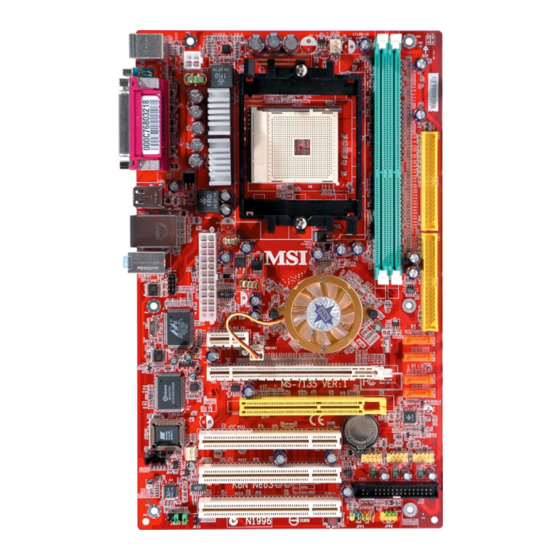
Page 12: Quick Components Guide
MS-7135 ATX Mainboard Quick Components Guide CPU, p.E-7 JPW1, p.E-11 DDR DIMMs, p.E-10 CFAN1, p.E-15 Back Panel Top: Mouse C FAN1 Bottom: Keyboard I/O, p.E-13 JPW 1 Top: Parallel Port Bottom: C OM Port IDE1/2, p.E-15 U SB Ports T: LAN Jack... -
Page 13: Cpu Installation Procedures For Socket 754
Quick User’s Guide Central Processing Unit: CPU CPU Installation Procedures for Socket 754 1. Please turn off the power and unplug the power cord before O pen Lever installing the CPU. Sl i di ng 90 degree Pl at e 2. -
Page 14: Installing Amd Athlon64 Cpu Cooler Set
MS-7135 ATX Mainboard Installing AMD Athlon64 CPU Cooler Set W hen you are installing the CPU, make sure the CPU has a heat sink and a cooling fan attached on the top to prevent overheating. If you do not have the heat sink and cooling fan, contact your dealer to purchase and install them before turning on the computer. - Page 15 9. Attach the CPU Fan cable to the CPU fan connector on the mainboard. MSI Reminds You... While disconnecting the Safety Hook from the fixed bolt, it is neces- sary to keep an eye on your fingers, because once the Safety Hook is...
- Page 16 MS-7135 ATX Mainboard Memory The mainboard provides 2 slots for 184-pin DDR DIMM (Double In-Line Memory Module) modules and supports the memory size up to 2GB. You can install DDR 333/ 400 modules on the DDR DIMM slots (DIMM 1~2).
-
Page 17: Power Supply
JPW1 Pin Definition SIGNAL JPW1 MSI Reminds You... 1. These two connectors connect to the ATX power supply and have to work together to ensure stable operation of the mainboard. 2. Power supply of 350 watts (and above) is highly recommended for system stability. -
Page 18: Important Notification About Power Issue
MS-7135 ATX Mainboard Important Notification about Power Issue nVIDIA chipset is very sensitive to ESD (Electrostatic Discharge), therefore this issue mostly happens while users intensively swap memory modules under S5 (power-off) states, and the power code is plugged while installing modules. Due to several pins are very sensitive to ESD, so this kind of memory-replacement actions might cause chipset system unable to boot. - Page 19 Quick User’s Guide Back Panel L-In Parallel M ou se L-Out Keyboard Serial Port USB Ports M ouse/Keyboard Connector RJ-45 LAN Jack Pin5 Mouse/KBD Clock Pin6 NC Pin4 VCC Pin3 GND Gigabit LAN (Optional) Pin1 Pin2 NC Mouse/KBD SIGNAL DESCRIPTION DATA Differential Pair 0+ Differential Pair 0-...
- Page 20 MS-7135 ATX Mainboard Connectors Floppy Disk Drive Connector: FDD1 The mainboard provides a standard floppy disk drive connector that supports 360K, 720K, 1.2M, 1.44M and 2.88M floppy disk types. FDD1 CD-In Connector: J1 This connector is provided for CD-ROM audio.
- Page 21 +12V CFAN1 SFAN1 NBFAN1 MSI Reminds You... 1. Always consult the vendors for proper CPU cooling fan. 2. CFAN1 supports Smart Fan control. You can install Core Center utility that will automatically control the CPU fan speed according to the actual CPU temperature. Alternatively, you may set up the smart fan control functions in the BIOS setup utility.
- Page 22 MS-7135 ATX Mainboard JCOM1 Serial Port Header: JCOM1 Data Carry Serial In The mainboard offers one 9-pin header as serial port. Detect Data The port is a 16550A high speed communication port that Serial Out Terminal sends/receives 16 bytes FIFOs. You can attach a serial...
- Page 23 USB1+ Connect to JUSB1, JUSB2, or USB 2.0 Bracket JUSB3 (Optional) MSI Reminds You... Note that the pins of VCC and GND must be connected correctly to avoid possible damage. Jumpers/Buttons Clear CMOS Button: SW_BAT1 CMOS stands for Complementary Metal-Oxide Semiconductor and is more spe- cifically referred to as CMOS RAM.
- Page 24 MS-7135 ATX Mainboard Slots The motherboard provides one PCI Express x1 slot, one PCI Express x16 slot, three 32-bit PCI slots, and one AGR slot. PCI (Peripheral Component Interconnect) Express Slots The PCI Express slots support high-bandwidth, low pin count, and serial interconnect technology.
- Page 25 VGA BIOS VGA Driver MB Driver (from NVOM011 CD) MSI Reminds You... The VGA BIOS and driver versions need to be identical to the ver- sions in the compatibility list in order to have the AGR function work properly. E-19...
- Page 26 MS-7135 ATX Mainboard MS-7135 V GA CARD Model nam e V GA Chip VGA M em ory VGA BIOS Vender SPEED Re sult Driver Ve r. Alvatron FX5700U GeForce FX5700 Ultra 128MB/DDR SDRAM 4.36.20.18.01 Pass 6.14.10.6681 Fire GL 8800 Fire GL 8800 128MB/SDRAM 1.03...
- Page 27 Quick User’s Guide VGA CARD MS-7135 Model name VGA Chip VGA Memory VGA BIOS Vender SPEED Result Driver Ver. 51 MSI MS-8888 GeForce 4 MX 440 64MB/DDR SDRAM 4.18.20.03.00 Pass 6.6.8.1 52 MSI MS-8889 GeForce 4 Ti 4200 128MB/DDR SDRAM 4.28.20.05.02 Pass 6.6.8.1...
- Page 28 MS-7135 ATX Mainboard BIOS Setup Power on the computer and the system will start POST (Power On Self Test) process. W hen the message below appears on the screen, press <DEL> key to enter Setup. P r e s s...
- Page 29 Quick User’s Guide The Main Menu Standard CMOS Features Use this menu for basic system configurations, such as time, date etc. Advanced BIOS Features Use this menu to setup the items of special enhanced features. Advanced Chipset Features Use this menu to change the values in the chipset registers and optimize your system’s performance.
- Page 30 MS-7135 ATX Mainboard Cell Menu Current CPU / DDR Clock These two items show the current clocks of CPU & DDR. Read-only. High Performance M ode This field allows you to select the DDR timing setting. Setting to [Optimized] enables relevant overclocking settings automatically to be determined by SPD.
- Page 31 5th level of overclocking, increasing the CPU frequency by 9%. [Commander] 6th level of overclocking, increasing the CPU frequency by 11%. MSI Reminds You... 1. Even though the Dynamic Overclocking Technology is more stable than manual overclocking, basically, it is still risky. We suggest that users should make sure that the CPU can afford to overclocking regularly first.
- Page 32 MS-7135 ATX Mainboard sist of a new set of instructions and a new set of registers. These instructions and registers are designed to allow Single-Instruction Multiple-Data (SIMD) computations to be made on single-precision floating-point numbers. The Streaming SIMD Extensions 2 (SSE2) were introduced in the Pentium 4 and Intel Xeon processors.
- Page 33 Manuel d’Utilisation K8N Neo3 Series (MS-7135 v1.X) Carte Mère ATX Français...
- Page 34 Carte Mère ATX MS-7135...
- Page 35 MS-7135 (v1.X) Manuel d’Utilisation Féliciation vous venez d’acheter une carte mèreATX K8N Neo3 ® (MS-7135) v1.X. La K8N Neo3 est basée sur le chipset nVIDIA nForce4-4X offrant des performances importantes. Elle fonctionne ® avec les process eurs AM D K8 Athlon 64 et offre un système hautment perf ormant tant pour les partic uliers que pour les professionnels.
- Page 36 Carte Mère ATX MS-7135 Spécificités de la Carte † Processeurs AMD Socket-754 K8 Athlon 64 † Processeur Athlon 64 jusqu’à 3700 ou supérieur (Pour une mise à jour sur les dernières informations relatives au cPU, veuillez vi s i t e r : h t t p : / / w w w . m s i. c o m . t w / p r o g r a m / p r o d u c t s / m a i n b o a r d / m b d / pro_mbd_cpu_support.php)
- Page 37 Manuel d’Utilisation Pour créer ce CD, veuillez vous reporter à cette adresse : http://www.microsoft.com/windows2000/downloads/servicepacks/ sp4/HFdeploy.htm Interface USB † 10 ports USB - Controllé par le chipset nForce4-4X - 4 ports à l’arrière, 6 ports via bracket externe NV RAID (Logiciel) †...
- Page 38 Carte Mère ATX MS-7135 Guide des Composants CPU, p.F-7 JPW1, p.F-11 DDR DIMMs, p.F-10 CFAN1, p.F-15 Back Panel Top: Mouse C FAN1 Bottom: Keyboard I/O, p.F-13 JPW 1 Top: Parallel Port Bottom: C OM Port IDE1/2, p.F-15 U SB Ports...
- Page 39 Manuel d’Utilisation Central Processing Unit: CPU Procédures d’installation du CPU pour Socket 754 1. Veuillez éteindre et débrancher votr e PC avant l’installation du O pen Lever CPU. Sl i di ng 90 degree Pl at e 2. Tirez le levier vers le haut. Assurez-vous que celui-ci est bien en position ouverte maximum (angle de 90°).
- Page 40 Carte Mère ATX MS-7135 Installation du CPU AMD Athlon64 Quand vous installez votre CPU, assurez-vous que le CPU possède un système de refroidissement pour prévenir les surchauffes. MSI Vous Rappelle... Les images ci-dessous servent de démonstration pour l’installation de votre ventilateur pour Socket 754 CPUs uniquement. L’apparence de votre carte mère peut varier selon les modèles.
- Page 41 9.Connectez le câble d’alimentation sur le connecteur de la carte mère prévu à cet effet MSI Vous Rapelle... Lorsque vous déconnectez le crochet, il est nécessaire de garder un oeil sur vos doigts car une fois le crochet déconnecté, celui-ci reprend...
- Page 42 Carte Mère ATX MS-7135 Mémoire La carte mère procure 2 slots DDR DIMM (Double In-Line Memory Module) (184 broches) et supporte jusqu’à 2GB de mémoire. Vous pouvez installer les modules DDR 333/400 sur les slots DDR DIMM (DIMM 1~2). Memory Population Rules Installez au moins un module DIMM sur les slots.
- Page 43 Ce connecteur d’alimentation 12V permet l’alimentation du CPU. JPW1 Pin Definition SIGNAL JPW1 MSI Vous Rappelle... 1. Ce deux connecteurs ATX doivent fonctionner ensemble pour as- surer la stabilité de la carte mère. 2. Une alimentation de 350Watt (et plus) est fortement recommandé...
- Page 44 Carte Mère ATX MS-7135 Information Importante sur l’alimentation Le chipset NForce est très sensible à l’ESD (Décharge Eléctrostatique). Ce problème intevient la plupart du temps lorsque l’utilisateur change des modules de mémoire lorsque le pc est en veille (S5) et que l’alimentation est toujours connectée.
- Page 45 Manuel d’Utilisation Panneau Arričre L-In Parallèle Souris L-Out Clavier Port de série Ports USB Souris/Clavier RJ-45 LAN Pin5 Mouse/KBD Clock Pin6 NC Pin4 VCC Pin3 GND Gigabit LAN (Optionnel) Pin1 Pin2 NC Mouse/KBD SIGNAL DESCRIPTION DATA Differential Pair 0+ Differential Pair 0- Port de série SIGNAL Differential Pair 1+...
- Page 46 Carte Mère ATX MS-7135 Connecteurs Connecteur Floppy Disk : FDD1 La carte est pourvue d’un connecteur de disquette qui supporte les disques de 360K, 720K, 1.2M, 1.44M et 2.88M. FDD1 Connecteur CD-In : J1 Le connecteur est destiné au branchement audio du CD-ROM.
- Page 47 +12V +12V CFAN1 SFAN1 NBFAN1 MSI Vous Rappelle... 1. Toujours consulter votre revendeur au sujet du radiateur + ventilateur. 2. Vous pouvez installer l’utilitaire PC Alert pour contrôler la température du CPU et la vitesse de rotation du ventilateur. ®...
- Page 48 Carte Mère ATX MS-7135 JCOM1 Connecteur Port de Série : JCOM1 Data Carry Serial In La carte mère offre un connecteur port de série 9 Detect Data broches. C’est un port de communication haute vitesse Serial Out Terminal 16550A qui envoie/reçoit 16 bytes FIFOs. Vous pouvez...
- Page 49 USB1+ Connect to JUSB1, JUSB2, or USB 2.0 Bracket JUSB3 (Optionnel) MSI Vous Rappelle... A Noter que les broches VCC et GND doivent être correctement connecter. afin d’éviter tout endommagement. Cavaliers Cavalier Clear CMOS : SW_BAT1 Le CMOS ressemble plus à une RAM étant donné qu’il est équipé d’un semi conducteur.
- Page 50 Carte Mère ATX MS-7135 Slots La carte mère procure un slot PCI Express x1, un slot PCI Express x16, trois slots PCI 32-bit, et un slot AGR. Slots PCI (Peripheral Component Interconnect) Express Les slots PCI Express possèdent une large bande passante, supportent les plateformes desktop AMD haute performances utilisant le processeur AMD ainsi que les avantages de cette plateforme.
- Page 51 ViewSonic P225f 22”CRT VGA BIOS VGA Driver MB Driver (from NVOM011 CD) MSI Vous Rappelle... Les versions des BIOS et des pilotes doivent être identiques aux versions de la liste de compatibilité pour que la fonction AGR marche correctement. F-19...
- Page 52 Carte Mère ATX MS-7135 MS-7135 V GA CARD Model nam e V GA Chip VGA M em ory VGA BIOS Vender SPEED Re sult Driver Ve r. Alvatron FX5700U GeForce FX5700 Ultra 128MB/DDR SDRAM 4.36.20.18.01 Pass 6.14.10.6681 Fire GL 8800...
- Page 53 Manuel d’Utilisation VGA CARD MS-7135 Model name VGA Chip VGA Memory VGA BIOS Vender SPEED Result Driver Ver. 51 MSI MS-8888 GeForce 4 MX 440 64MB/DDR SDRAM 4.18.20.03.00 Pass 6.6.8.1 52 MSI MS-8889 GeForce 4 Ti 4200 128MB/DDR SDRAM 4.28.20.05.02 Pass 6.6.8.1...
-
Page 54: Setup Du Bios
Carte Mère ATX MS-7135 Setup du BIOS Allumez votre ordinateur, le système lance le processus de POST (Power On Self Test). Quand le message ci-dessous apparaît à l’écran, appuyez sur le bouton <DEL> pour entrer dans le setup. Press DEL to enter SETUP Si le message disparaît avant que vous ne puissiez entrer dans le setup,... -
Page 55: Menu Principal
Manuel d’Utilisation Menu Principal Standard CMOS Features Cette fonction permet le paramétrage des éléments standards du BIOS. Advanced BIOS Features Cette fonction permet de paramétrer des éléments avancés du Bios. Advanced Chipset Features Cette option vous permet de paramétrer les éléments relatifs au registre du chipset, permettant ainsi d’optimiser les performances de votre système. - Page 56 Carte Mère ATX MS-7135 Cell Menu Current CPU / DDR Clock Vitesse d’horloge des CPU & DDR. Lecture seule. High Performance M ode Sélectionner les paramètres the CPU/FSB. Options: [Manual], [Optimized]. Lorsque [Optimized] est sélectionné, le système utilisera des paramètres d’overclocking pour le CPU/FSB.
- Page 57 5ème niveau d’overclocking, augmentant la fréquence CPU de [Commander] 6ème niveau d’overclocking, augmentant la fréquence CPU de MSI Reminds You... 1. Even though the Dynamic Overclocking Technology is more stable than manual overclocking, basically, it is still risky. We suggest that users should make sure that the CPU can afford to overclocking regularly first.
- Page 58 Carte Mère ATX MS-7135 Instructions SSE/SSE2 Cet élément active/désactive les instructions SSE/SSE2. Le SSE (Streaming SIMD Extensions) est introduit avec les processeurs Pentium III. Les extensions SSE con- sis tent en un nouveau jeu d’instructions pour le registre. Ces fonctions s ont développées pour des instructions simples ou multiples (SIMD).
- Page 59 Kurzanleitung K8N Neo3 Series (MS-7135 V1.X) ATX Mainboard Deutsch...
- Page 60 MS-7135 ATX Mainboard...
- Page 61 Kurzanleitung MS-7135 (V1.X) Kurzanleitung Danke, dass Sie das K8N Neo3 (MS-7135) V1.X ATX Mainboard ® gewählt haben. Das K8N Neo3 Mainboard basiert auf dem nVIDIA nForce4-4X Chipsatz und ermöglicht somit ein optimales und ® effizientes System. Entworfen, um den hochentwickelten AMD Athlon 64 Prozessor aufzunehmen, stellt das Mainboard K8N Neo3 die ideale Lösung zum Aufbau eines professionellen...
- Page 62 † Drei 32-bit Master 3,3V/5V PCI- Bus Slots † Ein AGR (Advance Graphics Riser) Slot für kompatible AGP Grafikkarten (Um den letzten Stand bezüglich kompatibler AGP Grafikkarten zu erhalten, bes uc hen Sie bitte http://www.msi.c om.tw/program/products/mainboard/ mbd_index.php) Onboard IDE † Zwei im nVIDIA ®...
- Page 63 Kurzanleitung Entnehmen Sie bitte folgender Website, wie Sie eine kombinierte Installations- CD erstellen: h t t p : / / w w w . m i c r o s o f t . c o m / w i n d o w s 2 0 0 0 / d o w n l o a d s / servicepacks/sp4/HFdeploy.htm USB Schnittstellen †...
- Page 64 MS-7135 ATX Mainboard Schnellübersicht Komponenten CPU, S.G-7 JPW1, S.G-11 DDR DIMMs, S.G-10 CFAN1, S.G-15 H i n t e r e s Oben : M aus C FAN1 Unten: Tastatur Anschlusspaneel S.G-13 JPW 1 O ben: Parallele Schnittstelle U nten:...
- Page 65 Kurzanleitung Hauptprozessor: CPU Vorgehensweise beim CPU Einbau Sockel 754 1. Bitte Schalten Sie das System aus und ziehen Sie den Netzstecker, Hebel öffnen bevor Sie die CPU einbauen. 2. Ziehen Sie den Hebel leicht seitlich weg vom Sockel, heben Sie ihn danach bis zu einem W inkel von ca.
- Page 66 MS-7135 ATX Mainboard Installation des AMD Athlon64 CPU Kühlersets W enn Sie die CPU einbauen, stellen Sie bitte sicher, dass Sie auf der CPU einen Kühlkörper mit aktiven Prozessorlüfter anbringen, um Überhitzung zu vermeiden. Verfügen Sie über keinen aktiven Prozessorlüfter mit Kühlkörper, setzen Sie sich bitte mit Ihrem Händler in Verbindung, um einen solchen zu erwerben...
- Page 67 Kurzanleitung 5. Setzen Sie das Kühlerset auf den Rückhaltemechanismus. Haken Sie zuerst ein Ende des Haltebügels ein, dann drücken Sie das andere Ende des Bügels herunter, um das Kühlerset auf dem Rückhaltemechanismus zu befestigen. 6. Machen Sie den Sicherungshebel, den Sicherungs haken und den 7.
- Page 68 MS-7135 ATX Mainboard Speicher Das Mainboard bietet Platz für zwei 184-pin DDR SDRAM DIMMs (Double In-Line Memory Module) und unterstützt den Speicherausbau auf bis zu 2GB. Sie können DDR 333/400 Module in die DDR DIMM Sockel einsetzen (DDR 1- 2).
- Page 69 Kurzanleitung Stromversorgung Das Mainboard unterstützt zur Stromversorgung ATX Netzteile. Bevor Sie den Netzteils tecker einstec ken, stellen Sie stets s ic her, das s alle Komponenten ordnungsgemäß eingebaut sind, um Schäden auszuschließen. ATX 24-Pin Power Connector: JWR1 Pin 12 Hier können Sie ein ATX 24-Pin Netzteil anschließen. Wenn Sie die Verbindung herstellen, stellen Sie sicher, dass der Stecker in der korrekten Ausrichtung eingesteckt wird und die Pins ausgerichtet sind.
- Page 70 MS-7135 ATX Mainboard Wichtiger Hinweis: Probleme mit der Stromversorgung Der nVIDIA Chipsatz ist gegenüber statischen Entladungen sehr empfindlich, deswegen kommt es zu diesem Problem vornehmlich, wenn der Nutzer häufig Speichermodule im Modus S5 (Strom aus) austauscht, und das Stromkabel während des Tausches eingesteckt ist.
-
Page 71: Hinteres Anschlusspaneel
Kurzanleitung Hinteres Anschlusspaneel L-In Parallele Schnittstelle M aus L-Out Tastatur Serielle USB Ports Schnittstelle Maus-/Tastaturanschluss RJ-45 LAN Buchse Pin5 Mouse/KBD Clock Pin6 NC Pin4 VCC Pin3 GND Gigabit LAN (Optional) Pin1 Pin2 NC Mouse/KBD SIGNAL DESCRIPTION DATA Differential Pair 0+ Differential Pair 0- Serielle Schnittstelle SIGNAL... - Page 72 MS-7135 ATX Mainboard Anschlüsse Anschluss des Diskettenlaufwerks: FDD1 Das Mainboard verfügt über einen Standardanschluss für Diskettenlaufwerke mit 360 KB, 720 KB, 1,2 MB, 1,44 MB oder 2,88 MB Kapazität. FDD1 CD-Eingang: J1 Hier kann das Audiokabel des CD-ROM Laufwerkes angeschlossen werden.
- Page 73 +12V CFAN1 SFAN1 NBFAN1 MSI weist darauf hin... 1. Fragen Sie stets Ihren Händler nach einem geeigneten Lüfter. 2. CFAN1 unterstützt die Smart Lüfterkontrolle. Sie können das Utility Core Center installieren, dass den CPU Lüfter automatisch in Abhängigkeit von der tatsächlichen CPU Temperatur steuert.
- Page 74 MS-7135 ATX Mainboard JCOM1 Serielle Schnittstelle: JCOM1 Data Carry Serial In Dieses Mainboard verfügt über einen 9-Pin Stiftblock als Detect Data serielle Schnittstelle. Dabei handelt es sich um eine 16550A Serial Out Terminal Hochgeschwindigkeitskommunikations-schnittstelle, die 16 Ready Request Data Set Bytes FIFOs sendet/empfängt, zum direkten Anschluss von...
- Page 75 USB1+ Verbindung zu JUSB1, JUSB2, oder USB 2.0 Slotblech JUSB3 (Optional) MSI weist darauf hin... Bitte beachten Sie, dass Sie die mit VCC (Stromführende Leitung) und GND (Erdleitung) bezeichneten Pins korrekt verbinden müssen, ansonsten kann es zu Schäden kommen Steckbrücken/Schalter Taster zur CMOS Löschung : SW_BAT1...
- Page 76 MS-7135 ATX Mainboard Sockel Das Mainboard stellt einen PCI Express x1, einen PCI Express x16, drei 32-bit PCI Sockel und einen AGR Slot zur Verfügung. PCI (Peripheral Component Interconnect) Express Sockel Die PCI Express Slots verwenden eine serielle Anschlusstechnologie, die sich durch eine hohe Bandbreite und eine niedrige Anzahl an Pins auszeichnet.
- Page 77 P225f 22”CRT VGA BIOS VGA Driver MB Driver (from NVOM011 CD) MSI weist darauf hin... Die Version des BIOS und des Treibers müssen mit den in der Liste angegebenen identisch sein, um eine ordnungsgemäße Funktion des AGR zu ermöglichen. G-19...
- Page 78 MS-7135 ATX Mainboard MS-7135 Hersteller Model Name VGA Chip VGA Memory VGA BIOS Geschw. Ergebn. Treiber Ver. Alvatron FX5700U GeForce FX5700 Ultra 128M B/DDR SDRAM 4.36.20.18.01 Best. 6.14.10.6681 Fire GL 8800 Fire GL 8800 128M B/SDRAM 1,03 Best. 6.14.10.6462 GAINWARD...
- Page 79 Kurzanleitung MS-7135 Hersteller Model Name VGA Chip VGA Memory VGA BIOS Geschw. Ergebn. Treiber Ver. MS-8888 GeForce 4 MX 440 64MB/DDR SDRAM 4.18.20.03.00 Best. 6.6.8.1 MS-8889 GeForce 4 Ti 4200 128M B/DDR SDRAM 4.28.20.05.02 Best. 6.6.8.1 MS-8890 GeForce 4 MX 440 64MB/DDR SDRAM 4.18.20.07.23...
- Page 80 MS-7135 ATX Mainboard BIOS Setup Nach dem Einschalten beginnt der Computer den POST (Power On Self Test - Selbstüberprüfung nach Anschalten). Sobald die Meldung unten erscheint, drücken Sie die Taste <Entf>(<Del>) um das Setup aufzurufen. Press DEL to enter SET UP W enn die Nachricht verschwindet, bevor Sie reagieren und Sie möchten immer noch...
- Page 81 Kurzanleitung The Main Menu Standard CMOS Features In diesem Menü können Sie die Basiskonfiguration Ihres Systems anpassen, so z.B. die Uhrzeit, das Datum usw. Advanced BIOS Features Verwenden Sie diesen Menüpunkt, um spezifische weitergehende Einstellungen an Ihrem System vorzunehmen. Advanced Chipset Features Verwenden Sie dieses Menü, um die Werte in den Chipsatzregistern zu ändern und die Leistungsfähigkeit Ihres Systems zu optimieren.
- Page 82 MS-7135 ATX Mainboard Cell Menu Current CPU / DDR Clock Diese beiden Punkte zeigen die derzeitige Taktung von CPU & DDR an. Nur Anzeige. High Performance M ode Gestattet Ihnen die Einstellungen des DDR Timings. Die Einstellung [Optimized] gestattet es relevante Einstellungen für das Übertakten automatisch durch das SPD zu bestimmen.
- Page 83 [General] [Commander] Sechste Übertaktungsstufe, Steigerung der CPU Frequenz um 11%. MSI weist darauf hin... 1. O bgleich Dy namic O vercloc k ing Tec hnology s tabiler is t, als manuelles Übertakten, ist es dennoch grundsätzlich riskant. Es ist empfehlenswert z uerst sic her z u stellen, dass Ihre CPU eine regelmäßige Übertaktung verträgt.
- Page 84 MS-7135 ATX Mainboard Erweiterungen bestehen aus einem neuen Satz von Befehlen und einem neuen Satz von Registern. Diese Befehle und Register wurden entworfen, um Single-Instruction Multiple-Data (SIMD) Berec hnungen mit einf ach präzisen Fließkommazahlen durchzuführen. Die Streaming SIMD Extensions2 (SSE2) wurden mit den Pentium 4 und Intel Xeon Prozessoren eingeführt.
Need help?
Do you have a question about the MS-7135 and is the answer not in the manual?
Questions and answers