
Subscribe to Our Youtube Channel
Related Manuals for SifWeld Evolution TS320ACDC


Summary of Contents for SifWeld Evolution TS320ACDC
- Page 1 Peters House The Orbital Centre Icknield Way Letchworth Garden City Hertfordshire SG6 1ET Tel. +44 (0) 845 130 7757 TI G Sifweld Evolution TS320ACDC Approved Operation Manual TSXE3T320AC...
- Page 2 The RoSH Directive 2011/65/EC, entering into force 2 January 2013 Type of Equipment Welding power source for TIG/TAG, MMA welding Brand name or trade mark SifWeld® Evolution Type designation etc. TS320ACDC Manufacturer or his authorised representative established within the EEA...
- Page 3 Safety Guidelines These general safety norms cover both arc welding machines and plasma cutting machines unless otherwise noted. The equipment must only be used for the purpose it was designed for. Using it in any other way could result in damage or injury and in breach of the safety rules. Only suitably trained and competent persons should use the equipment.
- Page 4 Wear suitable protective flame resistant clothing. The sparks and spatter from welding, hot work pieces, and hot equipment can cause fires and burns. Welding on closed containers, such as tanks, drums, or pipes, can cause them to explode. Accidental contact of electrode to metal objects can cause arcs, explosion, overheating, or fire.
- Page 5 LF Declaration Consult the data plate on the equipment for the power supply requirements. Due to the elevated absorbency of the primary current from the power supply network, high power systems affect the quality of power provided by the network. Consequently, connection restrictions or maximum impedance requirements permitted by the network at the public network connection point must be applied to these systems.
-
Page 6: Table Of Contents
Contents Preface General Introduction Technical Specifications Overview of Machine Control Panels MMA Display HF/Lift TIG Display Pulse TIG Display TIG SPOT Display JOB Programme 2T & 4T Mode Installation Switch Torch control Wireless Foot Pedal & Wireless Remote Control Pedal Switch Control Operation Troubleshooting Maintenance... -
Page 7: Preface
For your own safety and that of your working environment, pay particular attention to the safety instructions in the manual. For more information on SifWeld products, consult an authorised SifWeld dealer, or visit the SifWeld web site at www.sifweld.com. The specifications presented in this manual are subject to change without prior notice. -
Page 8: Introduction
1.2 Introduction The advanced SIFWELD EVOLUTION AEROTECH range of AC/DC TIG machines have features normally only available on high end Aerospace specific TIG welding machines, including: Four Power levels of HF Ignition Strength. Fully adjustable Cleaning and Welding Current Levels on both the Positive and Negative parts of the AC Square Wave Cycle. -
Page 9: Technical Specifications
1.3 Technical Specifications SifWeld Evolution TS320ACDC Power source 3~400V±10%, 50/60Hz Max input current (A) 19.3 18.4 25.4 23.9 Max input power (KW) 13.4 12.8 17.5 16.6 Power factor Welding current range (A) 10~320 Max no load voltage (V) 73.9 73.7... -
Page 10: Overview Of Machine
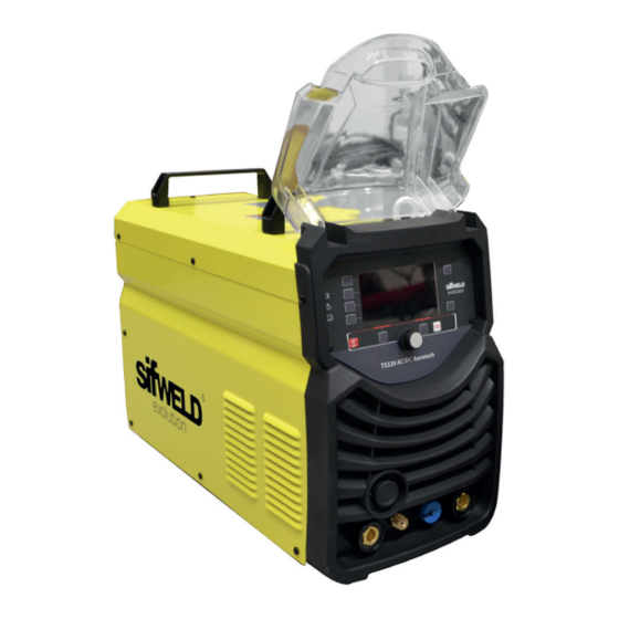
INSTALLATION & OPERATION §3 Installation & Operat §3.1 Layout for Front and Rear panel §3.1.1 Layout for welder 1.4 Overview of Machine Front View Power Source Front Panel Layout INSTALLATION & OPERATION 1. Negative output 2. Shield gas connector stallation & Operation 3. -
Page 11: Control Panels
Outlet (5) and inlet (6) for MIG The two nozzles on the same side of Control connector (4) are used for MIG operation and can be connected to the nozzles on the wire feeder. Blue corresponds to the outlet: cold water is delivered from the tank; red corresponds to the backwater inlet: hot water is flowed into the tank for cooling. -
Page 12: Mma Display
INSTALLATION & OPERATION 2.1 MMA Display §3.2.2 MMA display introduction 1. Welding mode key: Press it to enter MMA welding mode. 1. Welding mode key 2. Out waveform key: Press it to select DC output or AC Square wave output. Press it to enter MMA welding mode. -
Page 13: Hf/Lift Tig Display
INSTALLATION & OPERATION 2.2 HF/LIFT TIG Display §3.2.3 HF/LIFT TIG display introduction 1. Welding mode key: Press it to enter HF TIG or Lift TIG welding mode. 1. Welding mode key: Press it to enter HF TIG or Lift TIG welding mode. 2. -
Page 14: Pulse Tig Display
6. Parameter B key: Press it to select AC Frequency. Setting range: 50 - 250Hz. 7. Function A key: Press it to select Pre-gas time, Start arc current and Up slope time. 8. Function A key: Press it to select Down slope time, End arc current and Post-gas time, HF start power INSTALLATION &... -
Page 15: Tig Spot Display
2.4 TIG Spot Display INSTALLATION & OPERATION §3.2.5 TIG Spot display introduction INSTALLATION & OPERATION §3.2.5 TIG Spot display introduction 1. Current display: 10-400A (320A for BT TIG 321). 1. Current display: 10-400A (320A for BT TIG 321). 2. T display: 0.1 - 1.0s. -
Page 16: 4T Mode
2.6 2T & 4T Mode INSTALLATION & OPERATION 2T Mode 2T MODE The trigger is pulled and held on to activate the welding circuit, when the trigger is The trigger is pulled and held on to activate the welding circuit, when the trigger is released, the released, the welding circuit stops. - Page 17 PANEL FUNCTIONS & DESCRIPTIONS 4T MODE This is known as ’latching’ mode. The trigger is pulled once and released to activate the welding circuit, welding circuit, pulled and released again to stops the welding circuit. This function is pulled and released again to stops the welding circuit. This function is useful to longer welds as the useful to longer welds as the trigger is not required to be held on continuously.
-
Page 18: Installation
3. Installation Unpacking Check the packaging for any signs of damage. Carefully remove the machine and retain the packaging until the installation is complete. Location The machine should be located in a suitable position and environment. Care should be taken to avoid moisture, dust, steam, oil or corrosive gases. - Page 19 panel (0.0~10S); (12) t7: Electromagnetic valve is closed and stop argon flowing. Welding is finished. §3.3 Installation & Operation for MMA welding §3.3.1 Set up installation for MMA Welding Connection of Output Cables MMA Welding Two sockets are available on this welding machine. For MMA welding the electrode holder is shown be Two sockets are available on this welding machine.
- Page 20 TIG Welding 1. Insert the earth cable plug into the positive socket on the front of the machine and tighten it. 2. Plug the welding torch into the negative socket on the front panel, and tighten it. 3. Connect the gas line of TIG Gun to outlet gas connector on the front of the machine. 4.
-
Page 21: Switch Torch Control
2.4mm .800 12 - 90 12 - 180 2.4mm 1.100 15 - 150 15 - 250 3.2mm 1.100 20 - 200 20 - 300 3.2mm 1.500 25 - 250 25 - 350 3.1 Switch Torch Control §3.4.7 Gun switch control current UP/DOWN GUN INSTALLATION &... -
Page 22: Wireless Foot Pedal & Wireless Remote Control
3.2 Wireless Foot Pedal & Wireless Remote Control TIG series of welding machines can be configured to communicate exclusively with wireless foot pedal. This is done by a simple process of synchronising the wireless remote control and the machine frequencies. Each interface frequency assigned is unique, so it is possible to use several wireless control systems/ machines in the same area with no problems. -
Page 23: Pedal Switch Control
INSTALLATION & OPERATION succeed. 3.3 Pedal Switch Control §3.4.8 Pedal switch control ● When plug the twelve-lead aero-socket of pedal switch in it. Welder will identify the pedal switch, the welding current knob on the front panel will can’t use,and only 2T can When plug the twelve-lead aero-socket of pedal switch in it. -
Page 24: Operation
4. Operation Before starting any welding activity ensure that you have suitable eye protection and protective clothing. Also take the necessary steps to protect any persons within the area. Wire types and sizes Use the correct wire type for the base metal being welded. Use stainless steel wire for stainless steel, alumi- num for aluminum and steel wires for steel. -
Page 25: Troubleshooting
5. Troubleshooting Error Type Code Description Over-heating (1st thermal relay) Over-heating (2nd thermal relay) Thermal relay Over-heating (3rd thermal relay) Over-heating (4th thermal relay) Over-heating (Program default) Phase loss No gas Welding machine Under voltage Over voltage Over current Wire feeder over load Button fault on operating panel when switch on the machine Other faults on operating panel when switch on the machine Switch... -
Page 26: Maintenance
6. Maintenance The utilisation level of the power source and its working environment should be taken into consideration in planning the frequency of maintenance of the machine. Appropriate use and preventive maintenance guarantee the best trouble-free use of the equipment. This allows you to avoid interruptions in use and increases the productivity of the machine. -
Page 27: Warranty
Weldability Sif or an Authorised SifWeld Service Centre, in order to maintain validity of the extended warranty. Service visits can be booked online at www.sifweld.com or by calling 0870 330 7757 and will be charged at an average of £65 net per hour of travel/ servicing time. - Page 28 ® Peters House, The Orbital Centre, Icknield Way, Letchworth Garden City, Hertfordshire, SG6 1ET Tel. +44 (0) 845 130 7757 | Fax. +44 (0) 800 970 7757 | Email. sales@weldability-sif.com | www.sifweld.com www.sifweld.com...
Need help?
Do you have a question about the Evolution TS320ACDC and is the answer not in the manual?
Questions and answers