
Subscribe to Our Youtube Channel
Related Manuals for SifWeld Evolution CUT40 Air


Summary of Contents for SifWeld Evolution CUT40 Air
- Page 1 Peters House The Orbital Centre Icknield Way Letchworth Garden City Hertfordshire SG6 1ET Tel. +44 (0) 345 130 7757 PL ASMA SifWeld Evolution CUT40 Air Approved Operation Manual TSXE1P40C...
- Page 2 The RoSH Directive 2011/65/EC, entering into force 2 January 2013 Type of Equipment Plasma Cutter Brand name or trade mark SifWeld® Evolution Type designation etc. TSXE1P40C Manufacturer or his authorised representative established within the EEA Name, address, telephone no, fax no...
- Page 3 Safety Guidelines These general safety norms cover both arc welding machines and plasma cutting machines unless otherwise noted. The equipment must only be used for the purpose it was designed for. Using it in any other way could result in damage or injury and in breach of the safety rules. Only suitably trained and competent persons should use the equipment.
- Page 4 Wear suitable protective flame resistant clothing. The sparks and spatter from welding, hot work pieces, and hot equipment can cause fires and burns. Welding on closed containers, such as tanks, drums, or pipes, can cause them to explode. Accidental contact of electrode to metal objects can cause arcs, explosion, overheating, or fire.
- Page 5 LF Declaration Consult the data plate on the equipment for the power supply requirements. Due to the elevated absorbency of the primary current from the power supply network, high power systems affect the quality of power provided by the network. Consequently, connection restrictions or maximum impedance requirements permitted by the network at the public network connection point must be applied to these systems.
-
Page 6: Table Of Contents
Contents Preface General Introduction Technical Specifications Overview of Machine Control Panels Display Instruction Further Controls Air Check Display Installation Air Connections Operation Cutting Operation Troubleshooting Maintenance Warranty... -
Page 7: Preface
For your own safety and that of your working environment, pay particular attention to the safety instructions in the manual. For more information on SifWeld products, consult an authorised SifWeld dealer, or visit the SifWeld web site at www.sifweld.com. The specifications presented in this manual are subject to change without prior notice. -
Page 8: Introduction
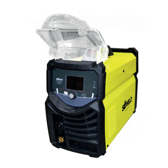
The SifWeld Cut40 AIR can be used to efficiently cut mild and low alloy steels, stainless, aluminium, copper, titanium and nickel alloys. -
Page 9: Technical Specifications
1.3 Technical Specifications SifWeldEvolution CUT40 AIR Rated Input Voltage (V) 1-230±10% Frequency (HZ) 50/60 28.2 Rated Input current (A) Rated Input Power (KW) Cutting Current Adjustment Range (A) 20~40 No Load Voltage (V) Duty Cycle (40 C 10 minutes) 20% 40A 100% 30A External Air Severance Cut for Carbon Steel (mm) ≤... -
Page 10: Overview Of Machine
PANEL FUNCTIONS & DESCRIPTIONS §3 Panel Functions & Desc §3.1 Front and rear panel layout of welding 1.4 Overview of Machine Front View Power Source Front Panel Layout 1. Cutting gun connector 2. Positive output cable 1. Cutting gun connector: Connected to the cutting machin 2. -
Page 11: Control Panels
PANEL FUNCTIONS & DESCRIPTIONS 2. Control Panels §3.2 Control panel of welding machine §3.2.1 Panel introduction 1. Trigger mode button: Press the key to select 2T or 4T trigger mode. 1. Trigger mode button 2. Cutting current knob: counterclockwise rotation reduces the current and clockwise Press the button to select 2T or 4T trigger mode. -
Page 12: Display Instruction
PANEL FUNCTIONS & DESCRIPTIONS 2.1 Display Introduction §3.2.2 Display introduction 1. Current display: This is current display. Adjust it by the knob. Unit: A. the range of 1. Current display adjustment is 20~40A. This is current display. Adjust it by the knob. Unit: A. the range of adjustment is 20~40A. 2. -
Page 13: Further Controls
PANEL FUNCTIONS & DESCRIPTIONS PANEL FUNCTIONS & DESCRIPTIONS Further Controls Explained 2.2 Further Controls Explained Further Controls Explained Trigger mode display (2) Trigger mode display (2) ⚫ When 2T operation is selected, pressing trigger starts gas, touch and lift arc to start. TRIGGER MODE DISPLAY Release trigger to stop gas and arc. -
Page 14: Air Check Display
PANEL FUNCTIONS & DESCRIPTIONS PANEL FUNCTIONS & DESCRIPTIONS 2.3 Air Check Display Air check display (3) Air check display (3) Press the air check button to check whether the air passage is smooth. If the machine is working Press the air check key to check whether the air passage is smooth. If the machine is properly, the screen will display the air pressure value normally, as shown in the figure below: Press the air check key to check whether the air passage is smooth. -
Page 15: Installation
3. Installation Unpacking Check the packaging for any signs of damage. Carefully remove the machine and retain the packaging until the installation is complete. Location The machine should be located in a suitable position and environment. Care should be taken to avoid moisture, dust, steam, oil or corrosive gases. -
Page 16: Operation
4. Operation OPERATION Before starting any welding activity ensure that you have suitable eye protection and protective clothing. Also take the necessary steps to protect any persons within the area. §5 Operation Cutting Preparation §5.1 Cutting Preparation 1. Tightly connect the power cable to electrical socket outlet (the input voltage, refer to the section 2 1) Tightly connect the power cable to electrical socket outlet (the input voltage, refer to technology parameters). -
Page 17: Troubleshooting
OPERATION Note: 1) If the alarm appears on the screen when cutting, it is needed to loose the switch of OPERATION the gun until the alarm release, then press on the switch to restart working. Note: 2) In the automatic gas test and examine, press on the cutting gun, there will no 5. -
Page 18: Maintenance
6. Maintenance The utilisation level of the power source and its working environment should be taken into consideration in planning the frequency of maintenance of the machine. Appropriate use and preventive maintenance guarantee the best trouble-free use of the equipment. This allows you to avoid interruptions in use and increases the productivity of the machine. -
Page 19: Warranty
Weldability Sif or an Authorised SifWeld Service Centre, in order to maintain validity of the extended warranty. Service visits can be booked online at www.sifweld.com or by calling 0870 330 7757 and will be charged at an average of £65 net per hour of travel/ servicing time. - Page 20 ® Peters House, The Orbital Centre, Icknield Way, Letchworth Garden City, Hertfordshire, SG6 1ET Tel. +44 (0) 345 130 7757 | Fax. +44 (0)1462 600060 | Email. sales@weldability-sif.com | www.sifweld.com www.sifweld.com...
Need help?
Do you have a question about the Evolution CUT40 Air and is the answer not in the manual?
Questions and answers