
Subscribe to Our Youtube Channel
Related Manuals for SifWeld Evolution MTS400 SYN


Summary of Contents for SifWeld Evolution MTS400 SYN
- Page 1 Peters House The Orbital Centre Icknield Way Letchworth Garden City Hertfordshire SG6 1ET Tel. +44 (0) 845 130 7757 M IG TI G SifWeld Evolution MTS400 SYN Approved Operation Manual TSXE3D400MTS...
- Page 2 The RoSH Directive 2011/65/EC, entering into force 2 January 2013 Type of Equipment Welding power source for MIG/MAG, TIG/TAG, MMA welding Brand name or trade mark SifWeld® Evolution Type designation etc. MTS400 SYN Manufacturer or his authorised representative established within the EEA...
- Page 3 Safety Guidelines These general safety norms cover both arc welding machines and plasma cutting machines unless otherwise noted. The equipment must only be used for the purpose it was designed for. Using it in any other way could result in damage or injury and in breach of the safety rules. Only suitably trained and competent persons should use the equipment.
- Page 4 Wear suitable protective flame resistant clothing. The sparks and spatter from welding, hot work pieces, and hot equipment can cause fires and burns. Welding on closed containers, such as tanks, drums, or pipes, can cause them to explode. Accidental contact of electrode to metal objects can cause arcs, explosion, overheating, or fire.
- Page 5 LF Declaration Consult the data plate on the equipment for the power supply requirements. Due to the elevated absorbency of the primary current from the power supply network, high power systems affect the quality of power provided by the network. Consequently, connection restrictions or maximum impedance requirements permitted by the network at the public network connection point must be applied to these systems.
-
Page 6: Table Of Contents
Contents Preface General Introduction Technical Specifications Overview of Machine Control Panels MMA Display Lift TIG Display MIG Manual Display MIG SYN Display Spool Gun Display Installation Torch switch Control Remote Torch Control Pedal Switch Control Wire Feed Roller Wire Installation MIG Torch Liner Operation Spool Gun... -
Page 7: Preface
For your own safety and that of your working environment, pay particular attention to the safety instructions in the manual. For more information on SifWeld products, consult an authorised SifWeld dealer, or visit the SifWeld web site at www.sifweld.com. The specifications presented in this manual are subject to change without prior notice. -
Page 8: Introduction
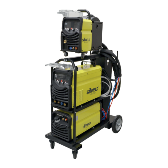
1.2 Introduction The SifWELD MTS400SYN is a professional, microprocessor-controlled inverter welding package for MIG, MMA & Lift-TIG applications . With 100% Duty Cycle at 400A and 60% at 500A this machine is the ideal work horse for high production manufacturing in air cooled or water cooled versions. Using the built in synergic facility the machine will automatically give the optimum welding parameters for the specific material, wire size and shielding gas. -
Page 9: Technical Specifications
1.3 Technical Specifications SifWeldEvolution MTS400 SYN Input Voltage (V) 3~400±10% Frequency (HZ) 50/60 Input Current (A) 33.1 41.8 Input Power (KW) 28.4 22.9 28.9 Welding Current (A) 40~500 10~500 10~500 Welding Voltage (V) 16~39 10.4~30 20.4~40 No-load Voltage (V) 58.1 70.1 67.1 Duty cycle (40... -
Page 10: Overview Of Machine
PANEL FUNCTIONS & DESCRIPTIONS Panel Functions & Descriptio § Machine Layout Description §Front and rear panel layout of welding machine 1.4 Overview of Machine Front View Power Source Front Panel Layout 1. Negative Output 2. Gas outlet 3. TIG gun control connector. 4. - Page 11 PANEL FUNCTIONS & DESCRIPTIONS PANEL FUNCTIONS & DESCRIPTIONS Front and rear panel layout of water cooling Front and rear panel layout of water cooling Front View Water Cooler Front Panel Layout 1. Intake: From here, water or coolant, antifreeze, etc. can be injected into tank. 2.
-
Page 12: Control Panels
2. Control Panels PANEL FUNCTIONS & DESCRIPTIONS §3.2 Front Panel Functions and Descriptions 2.1 MMA Display §3.2.1 MMA control panel 1. Welding mode button: Press it to select MMA welding mode. 1. Welding mode button 2. L parameter knob: Rotate it to adjust welding current. Press it to select MMA welding mode. -
Page 13: Lift Tig Display
2.2 LIFT TIG Display PANEL FUNCTIONS & DESCRIPTIONS §3.2.2 Lift TIG control panel 1. Welding mode button: Press it to select TIG Lift welding mode. 1. Welding mode button 2. L parameter knob: Rotate it to adjust welding current. In functional parameter Press it to select TIG Lift welding mode. - Page 14 1. Welding mode button: Press it to select TIG Lift welding mode. 2. L parameter knob: Rotate it to adjust welding current. In functional parameter interface, rotate it to select parameters. 3. R parameter knob: Rotate it to adjust Down Slope time and other parameters. Function Interface 4.
- Page 15 Trigger Mode Select PANEL FUNCTIONS & DESCRIPTIONS Trigger mode select: 2T mode (ON/OFF) Pre Gas Time Slow Feed Time Post Gas Time Gun Switch Burn back Time Gas Supply Wire Feed Output Voltage Output Current Welding conditions 4T mode (Latching) Self-Locking Function Gun Switch Gas Supply...
-
Page 16: Mig Manual Display
2.3 MIG Manual Display PANEL FUNCTIONS & DESCRIPTIONS §3.2.3 MIG Manual control panel PANEL FUNCTIONS & DESCRIPTIONS panel (0.0~10S); (12) t7: Electromagnetic valve is closed and stop argon flowing. Welding is finished. §3.2.4 MIG Manual display introduction 1. Welding mode button: Press it to select MIG Manual welding mode. 2. -
Page 17: Mig Syn Display
Burnback PANEL FUNCTIONS & DESCRIPTIONS Short-circuit between welding wire and molten pool leads to the increase of current, which leads to the melting speed of welding wire too fast, and the wire feeding speed cannot keep up with, which makes §3.2.4 MIG SYN control panel the welding wire and workpiece disconnected. - Page 18 and shielding gas being used. Obviously other variables such as welding joint type and thickness, air temperature affect the optimal voltage and wire feed setting, so the program provides a voltage fine tuning function for the synergic program selected. Once the voltage is adjusted in a synergic program, it will stay fixed at this variation when the current setting is changed.
-
Page 19: Spool Gun Display
2.5 Spool Gun Display PANEL FUNCTIONS & DESCRIPTIONS §3.2.5 Spool Gun control panel PANEL FUNCTIONS & DESCRIPTIONS § Spool Gun control panel 1. Welding mode button: Press it to select Spool Gun welding mode. 1. Welding mode button Press it to select Spool Gun welding mode. 2. -
Page 20: Installation
3. Installation Unpacking Check the packaging for any signs of damage. Carefully remove the machine and retain the packaging until the installation is complete. Location The machine should be located in a suitable position and environment. Care should be taken to avoid moisture, dust, steam, oil or corrosive gases. - Page 21 INSTALLATION & OPERATION §4 Installation & Operation MMA Welding Two sockets are available on this welding machine, One Positive (+) and one Negative (-) polarity, §4.1 Installation & Operation for MMA Electrode Welding to connect MMA/Electrode holder cable and earth clamp cable. Various electrodes require different polarity for optimum results and careful attention should be paid to the polarity, refer to the electrode §4.1.1 Set-Up Installation manufacturers information for the correct polarity.
- Page 22 TIG Welding 1. Insert the earth cable plug into the positive socket on the front of the machine and tighten it. 2.Plug the welding torch into the negative socket on the front panel, and tighten it. 3. Connect the gas line of TIG Gun to outlet gas connector on the front of the machine. Check for Leaks! 4.
-
Page 23: Torch Switch Control
3.1 Torch Switch Control INSTALLATION & OPERATION §3.4.6 Gun switch control current UP/DOWN GUN Adjust current button, Torch switch when it’s pushed up, the current increase, when it’s pushed down, the current decrease. Remote Control Socket Socket Pin Function Not connected Not connected Not connected Not connected... -
Page 24: Remote Torch Control
DIAGRAM FOR GUN 3.2 Remote Torch Control REMOTE GUN Torch switch Socket Pin Function Not connected Not connected 10k ohm (maximum) connection to 10k ohm remote control potentiometer Wiper arm connection to 10k ohm remote control potentiometer Zero ohm (minimum) connection to 10k ohm remote control potentiometer Not connected Not connected Trigger Switch Input... -
Page 25: Pedal Switch Control
3.3 Pedal Switch Control DIAGRAM FOR GUN Pedal switch control • When plug the twelve-lead aero-socket of pedal switch in it. Welder will identify the pedal switch, the ● When plug the twelve-lead aero-socket of pedal switch in it. Welder will identify the welding current knob on the front panel will can’t use and only 2T can be selected. - Page 26 MIG Welding 1. Insert the earth cable plug into the negative socket on the front of the machine and tighten it. 2. Plug the welding torch into the MIG torch connection socket on the front panel of the wire feeder, and tighten it.
- Page 27 (9) Connect the power cable of welding machine with the output switch in electric box on site. NOTE: Air cooling mode without cooling device,and the water pipe is not needed for the air cooling mode. (10) Place wire onto spool holder - (spool (11) Feed wire over the drive roller into the 10.
- Page 28 INSTALLATION & OPERATION 15. Fit the correct size contact tip over the wire (11) Fit the correct sized contact tip and feed and fasten tightly into the tip holder. the wire through it, screw the contact tip into the tip holder of the torch head and nip it up tightly.
-
Page 29: Wire Feed Roller
3.4 Wire Feed Roller The importance of smooth consistent wire feeding during MIG welding cannot be emphasized enough. Simply put the smoother the wire feed then the better the weld. Feed rollers or drive rollers are used to feed the wire mechanically through the length of the welding gun cable. -
Page 30: Wire Installation
DIAGRAM FOR GUN DIAGRAM FOR GUN Wire Installation and Set Up Guide Wire Installation and Set Up Guide Again the importance of smooth consistent wire feeding during MIG welding cannot be 3.5 Wire Installation & Setup Again the importance of smooth consistent wire feeding during MIG welding cannot be emphasized enough. - Page 31 DIAGRAM FOR GUN DIAGRAM FOR GUN INSTALLATION & OPERAT 5. Feed the wire through the drive roller and 6. Lock down the top pressure roller and into the outlet guide tube of the wire feeder. apply a medium amount of pressure using the tension adjustment knob.
-
Page 32: Mig Torch Liner
3.6 MIG Torch liner Types MIG Torch Liners The liner is both one of the simplest and most important components of a MIG gun. Its sole purpose is to guide the welding wire from the wire feeder, through the gun cable and up to the contact tip. Steel Liners Most MIG gun liners are made from coiled steel wire also known as piano wire, which provides the liner with good rigidity and flexibility and allows it to guide the welding wire smoothly through the welding... -
Page 33: Operation
4. Operation Before starting any welding activity ensure that you have suitable eye protection and protective clothing. Also take the necessary steps to protect any persons within the area. 4.1 Spool Gun Display Set up installation for Spool Gun 1. Insert the earth cable plug into the negative (-) socket on the front of the machine and twist to tighten. 2.Connect the Spool Gun to the MIG torch connection socket on the front panel of the wire feeder, and tighten it. - Page 34 INSTALLATION & OPERATION (7) Connect the gas line to gas connector on the rear panel. INSTALLATION & OPERATION (8) Connect the power cord of welding machine with the outlet on electrical box. (7) Connect the gas line to gas connector on the rear panel. (8) Connect the power cord of welding machine with the outlet on electrical box.
- Page 35 INSTALLATION & OPERATION §4.4.2 Spool Gun Control 226 Spool Gun Gun switch Gun Switch Spool cover switch Adjust current button Spool Cover Switch Adjust Current Button Remote Control Socket Remote Control Socket Socket Pin Function Socket Pin Function Spool gun motor Not connected Spool gun motor Not connected...
-
Page 36: Troubleshooting
5. Troubleshooting Error Type Code Description Over-heating (1st thermal relay) Over-heating (2nd thermal relay) Thermal relay Over-heating (3rd thermal relay) Over-heating (4th thermal relay) Over-heating (Program default) Phase loss No water No gas Welding machine Under voltage Over voltage Over current Wire feeder over load Button fault on operating panel when switch on the machine Other faults on operating panel when switch on the machine... -
Page 37: Maintenance
6. Maintenance The utilisation level of the power source and its working environment should be taken into consideration in planning the frequency of maintenance of the machine. Appropriate use and preventive maintenance guarantee the best trouble-free use of the equipment. This allows you to avoid interruptions in use and increases the productivity of the machine. -
Page 38: Warranty
Weldability Sif or an Authorised SifWeld Service Centre, in order to maintain validity of the extended warranty. Service visits can be booked online at www.sifweld.com or by calling 0870 330 7757 and will be charged at an average of £65 net per hour of travel/ servicing time. - Page 39 Notes...
- Page 40 ® Peters House, The Orbital Centre, Icknield Way, Letchworth Garden City, Hertfordshire, SG6 1ET Tel. +44 (0) 845 130 7757 | Fax. +44 (0) 800 970 7757 | Email. sales@weldability-sif.com | www.sifweld.com www.sifweld.com...
Need help?
Do you have a question about the Evolution MTS400 SYN and is the answer not in the manual?
Questions and answers