Table of Contents
Advertisement
Quick Links
Advertisement
Table of Contents
Troubleshooting

Related Manuals for HP A6604


Summary of Contents for HP A6604
- Page 1 HP A6604 and A6608 Router Installation Manual...
-
Page 2: About This Manual
About This Manual Organization HP A6604/A6608 Routers Installation Manual is organized as follows: Chapter Contents Briefly introduces the product specifications, as well as 1 Router Overview the features and applications of the HP A6604/A6608. Describes the requirements on installation site, the... -
Page 3: Gui Conventions
Means a complementary description. Means techniques helpful for you to make configuration with ease. Related Documentation In addition to this manual, each HP A6600 Routers documentation set includes the following: Manual Description It is a guide for the user to perform the operations HP A6600 Routers User Manual correctly. -
Page 4: Environmental Protection
OAA, as well as a command index. This manual introduces all kinds of interface modules HP A6600 Routers Interface Card and Interface that SR6600 routers support, the means of Module Manual connection the interface cables and the interface module purchase guide. -
Page 5: Router Overview
The A6604 and A6608 can work at the core layer of small- and medium-sized enterprise networks or at the distribution layer and core layer of large-sized enterprise networks. They can also work at the access layer of carrier networks or large enterprise networks. -
Page 6: Physical Description
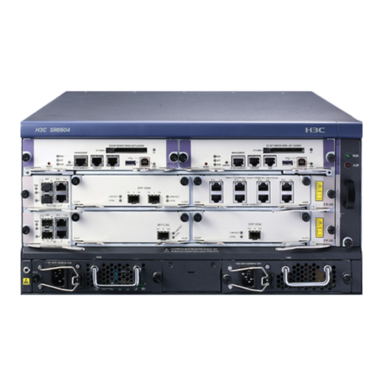
The A6604 and A6608 support two types of MPUs, route processing engine (RPE) and route switch engine (RSE). To facilitate description, the term "FIP" is used throughout this document to refer to the FIP- 100, FIP-110, FIP-200, and FIP-210 if not otherwise specified. - Page 7 Figure 1-2 Front view of the A6604 (configured with an RSE-X1) (1) Left mounting bracket (2) RSE-X1 (Slot 1) (3) Right mounting bracket (4) Chassis handle (5) Fan tray (6) AC power module (PWR 1) (7) PoE power module (reserved PoE slot)
-
Page 8: Rear View
(13) FIP slot (Slot 2) (RSE-X1 compatible) (14) Cable management bracket Currently, the device does not support power over Ethernet (PoE). Rear View Figure 1-5 Rear view of the A6604 (1) Warning label (2) Handle on the rear chassis panel... -
Page 9: System Specifications
System Specifications Dimensions, Weight and LPU Slots Table 1-2 Dimensions, weight and LPU slots Specification Item A6604 A6608 Dimensions without feet and 220 × 436 × 480 mm (8.66 × 308 × 476 × 436 mm (12.13 × mounting brackets (H × W × D) 17.17 ×... -
Page 10: Power Modules
40 × 140 × 354 mm (1.57 × 5.51 ×13.94 in.) Two power module slots are provided. The power Power module slots modules must have the same specifications. A6604: 75.9W~341.2W Power consumption range A6608: 86.4W~559W Online insertion and removal Supported Online insertion and removal of a power module refers to first switching off the power module and then removing it from the chassis or inserting it into the chassis. - Page 11 The power module is working normally. Solid red The power module is faulty. Fan Tray Table 1-5 Technical specifications for the fan tray Specification Fan (built-in) A6604 A6608 Rated voltage 12 VDC Total fan power consumption 30 W Automatic fan speed adjustment Supported 136.4 ×...
-
Page 12: Operating Environment
–60 m to +4 km (–196.85 ft. to +2.49 miles) System Software The device uses the Comware V5 software platform, HP's core software platform. Based on the IPv4/IPv6 dual stack, the Comware V5 software platform integrates link-layer protocols, routing, Multi-Protocol Label Switching (MPLS), Virtual Private Network (VPN), quality of service (QoS), security, and other data communications features. - Page 13 For details about the remove slot command, refer to Device Management in the System Volume of HP SR6600 Routers User Manual. LEDs...
- Page 14 Table 1-9 Description of the LEDs Status Meaning No power input is available, or the RPE-X1 has failed. Slow blinking The RPE-X1 is operating normally. (1 Hz) RUN (green) The application software is being loaded (in this case, Fast blinking never power off the device or hot-swap the RPE-X1;...
-
Page 15: Technical Specifications
RSE-X1 Front view Figure 1-11 Front view of RSE-X1 (1) Captive screw (2) Ejector lever (3) SMB coaxial clock interface (reserved) (4) RESET button (RESET) (5) CF card eject button (6) CF card slot (7) CF LED (CF) (8) USB interface 0 (0) (host mode) (9) USB interface 1 (1) (device mode) (10) USB interface 1 LED (USB) (11) Link state/data reception &... - Page 16 For details about the remove slot command, refer to Device Management in the System Volume of HP SR6600 Routers User Manual. LEDs...
- Page 17 Status Meaning A host is connected to the device-mode USB interface. The USB cable can be unplugged in this state. Data is being transmitted or received through the device- Blinking mode USB interface. In this state, do not unplug the USB cable.
- Page 18 1 GB Use CF cards provided by HP only. The device may be incompatible with other CF cards. CF cards less than 256 MB are not supported. CF card and slot Figure 1-13 CF card and slot...
- Page 19 Figure 1-14 Console cable Table 1-13 Console cable connector pinouts Console cable connector pinouts RJ-45 pin Signal direction DB-9 pin Signal — For the connection of the console cable, refer to “Connecting the Console Cable” in Chapter 4 For the connection of the console cable, refer to “Connecting the Console Cable”...
- Page 20 and a DB-25 (male) connector, of which you can select one to the serial 25 (male) connector, of which you can select one to the serial port on a modem as port on a modem as needed. Figure 1-15 AUX cable connectors AUX cable connectors Table 1-15 AUX cable connector pinouts AUX cable connector pinouts...
- Page 21 USB storage device is removed, information will also be displayed on the terminal, prompting the USB storage device has been removed. The device only supports the USB storage devices provided by HP and may be incompatible with those from other manufacturers.
- Page 22 Use the clock datetime time date command in user view to set the system date and time. For the description of the clock datetime command, refer to Basic System Configuration in the System Volume of HP SR6600 Routers User Manual. When a power failure occurs to the router, the clock module can continue working to ensure the system time is correct next time the router boots.
- Page 23 You can use the slave switchover command to perform a manual active-standby switchover. For details about the slave switchover command, refer to HA in the System Volume of HP SR6600 Routers User Manual. The standby RPE-X1 does not support any system configuration commands. Therefore, you ...
- Page 24 For details about the combo enable { copper | fiber } command, refer to Ethernet Interfaces in the Access Volume of HP SR6600 Routers User Manual. Use optical transceivers provided by HP only. The device may be incompatible with other optical transceivers and thus displays alarms automatically.
- Page 25 Slots An FIP-100 can be inserted in slot 2 or 3 of the A6604 and slot 2, 3, 4, or 5 of the A6608. FIP- 100 provides four MIM slots for some HP legacy MIMs. The MIM slots on FIP-100 are...
- Page 26 Slot 1 through Slot 4 respectively. Maximum interface modules provided by FIP-100s in full configuration Table 1-19 Maximum interface modules provided by FIP-100s in full configuration One RPE-X1 Two RPE-X1s One RSE-X1 Two RSE-X1s Interface module A6604 A6608 A6604 A6608 A6604 A6608 A6604 A6608 FIP-100...
- Page 27 Ethernet interface. You can use the combo enable { copper | fiber } command in interface view to switch between the optical and electrical interfaces. For details about the combo enable { copper | fiber } command, refer to Ethernet Interfaces in the Access Volume of HP SR6600 Routers User Manual.
- Page 28 An FIP-110 can be inserted in slot 2 or 3 of the 110 can be inserted in slot 2 or 3 of the A6604 and slot 2, 3, 4, or 5 of the and slot 2, 3, 4, or 5 of the A6608. FIP- 110 provides four MIM slots for some 110 provides four MIM slots for some HP legacy MIMs.
- Page 29 Introduction Flexible interface platform-200 (FIP-200), another type LPU of the device, provides a high- speed service processing capability. FIP-200 supports SR6600 HIMs and some HP legacy MIMs and provides two Combo interfaces. In consideration of the smooth upgrade requirements, FIP-200 supports two HIMs or two MIMs, or intermixing of an HIM and an MIM.
- Page 30 For details about the combo enable { copper | fiber } command, refer to Ethernet Interfaces in the Access Volume of HP SR6600 Routers User Manual. Use optical transceivers provided by HP only. The device may be incompatible with other optical transceivers and thus displays alarms automatically.
- Page 31 An FIP-200 can be inserted in slot 2 or 3 of the 200 can be inserted in slot 2 or 3 of the A6604 and slot 2, 3, 4, or 5 of the and slot 2, 3, 4, or 5 of the A6608.
- Page 32 Maximum interface modules provided by FIP-200s in full configuration Table 1-25 Maximum interface modules provided by FIP-200s in full configuration One RPE-X1 Two RPE-X1s One RSE-X1 Two RSE-X1s Interface module A6604 A6608 A6604 A6608 A6604 A6608 A6604 A6608 FIP-200...
- Page 33 Ethernet interface. You can use the combo enable { copper | fiber } command in interface view to switch between the optical and electrical interfaces. For details about the combo enable { copper | fiber } command, refer to Ethernet Interfaces in the Access Volume of HP SR6600 Routers User Manual.
- Page 34 An FIP-210 can be inserted in slot 2 or 3 of the 210 can be inserted in slot 2 or 3 of the A6604 and slot 2, 3, 4, or 5 of the and slot 2, 3, 4, or 5 of the A6608. The...
- Page 35 Maximum interface modules provided by FIP-210s in full configuration Table 1-28 Maximum interface modules provided by FIP-210s in full configuration One RPE-X1 Two RPE-X1s One RSE-X1 Two RSE-X1s Interface module A6604 A6608 A6604 A6608 A6604 A6608 A6604 A6608 FIP-210...
- Page 36 Ethernet interfaces. For details about the combo enable { copper | fiber } command, refer to Ethernet Interfaces in the Access Volume of HP SR6600 Routers User Manual. Technical specifications for Combo interfaces Technical specifications for electrical Ethernet interfaces ...
- Page 37 Operating mode 1000 Mbps in full duplex mode Use optical transceivers provided by HP only. The device may be incompatible with other optical transceivers and thus displays alarms automatically. RJ-45 connector The 10Base-T/100Base-TX/1000Base-T electrical Ethernet interfaces of the device use RJ-45 connectors and support MDI/MDI-X auto-sensing.
- Page 38 MT-RJ: square transceiver optical fiber connector RJ: square transceiver optical fiber connector Currently, the HP SR6600 routers support only the LC SR6600 routers support only the LC-type connectors. Figure 1-31 LC connector Before connecting a fiber, make sure that the received optical power at the local end does not...
- Page 39 Crossover cable: At both ends of a crossover cable, wires are crimped in the RJ-45 connectors in different sequences. A crossover cable is used to connect a (for example, PC or router) to another terminal. You can make crossover cables by yourself as needed. Table 1-32 Straight-through cable connector pinouts Category-5 RJ-45 pin...
- Page 40 No SFP module is shipped with the device. Use only the SFP modules provided by HP. The device cannot recognize SFP modules from other manufacturers. For the connection of electrical Ethernet interfaces or optical Ethernet interfaces, refer to ...
- Page 41 Accessories Chassis Accessory Before installing an RPE-X1 on the A6604/A6608, you need to insert a chassis accessory into Slot 0 or Slot 1. The chassis accessory can bear two RPE-X1s. For the installation of the chassis accessory and RPE-X1, refer to "Installing and Removing an RPE-X1" in Chapter 4 "Installing the Router."...
-
Page 42: Slot Arrangement
The device provides many types of interfaces, such as console, AUX, GigabitEthernet, serial (synchronous), POS, and E1 ports. This chapter describes how these interfaces are numbered. Figure 2-1 Slot arrangement on the A6604 configured with an RPE-X1 Figure 2-2 Slot arrangement on the A6604 configured with an RSE-X1... - Page 43 On a device configured with an RSE-X1, slots are numbered from Slot 1 instead of Slot 0. Slot Arrangement for MPUs and FIPs Table 2-1 Slot arrangement for MPUs Slot arrangement A6604 A6608 RPE-X1 (supporting 1+1 redundancy) Slot 0 and Slot 1...
-
Page 44: Numbering Interfaces
Type of the interface such as GE interface and serial interface. X: Number of the slot where the FIP resides, in the range of 2 to 3 on the A6604 and 2 to 5 on the A6608. - Page 45 Examples Example 1 A FIP-100 is installed in slot 3 and a MIM-2GBE module is installed in sub-slot 2 of the FIP-100. Numbers of fixed GigabitEthernet interfaces on the FIP-100 GigabitEthernet 3/0/0 GigabitEthernet 3/0/1 The sub-slot number Y of fixed GE interfaces on an LPU of the device is 0. Numbers of GigabitEthernet interfaces on the MIM-2GBE module If a MIM-2GBE is installed in slot 1 of the FIP-100, the numbers of GigabitEthernet interfaces are:...
- Page 46 GigabitEthernet 3/1/1 GigabitEthernet 3/1/2 GigabitEthernet 3/1/3 If a HIM-4GBE is installed in slot 2 of the FIP-200, the numbers of Gigabit Ethernet interfaces are: GigabitEthernet 3/2/0 GigabitEthernet 3/2/1 GigabitEthernet 3/2/2 GigabitEthernet 3/2/3 Example 4 A FIP-210 is installed in Slot 3 and a HIM-4GBE module is installed on the FIP-210.
-
Page 47: Preparing For Installation
Preparing for Installation Preparations for installing an A6604 and A6608 are similar. An A6608 is used in the examples in this chapter. Environment Requirements The device is designed for indoor application. To ensure the normal operation and prolong the service life, the installation site must meet the requirements mentioned hereunder. -
Page 48: Ventilation Requirements
Table 3-2 Limitation on dust concentration and diameter in the equipment room Diameter (μm) Concentration limit 1.4 x 10 7 x 10 2.4 x 10 1.3 x 10 (particles/m Concentration limit of harmful gases Besides, the contents of salt, acid, and sulfide in the equipment room of the router should be strictly restricted. -
Page 49: Electrostatic Discharge Prevention
An A6608 configured with an RPE-1X is taken as an example here. An ESD-preventive wrist strap is grounded in the same way on both the A6604 and the A6608. The following figure depicts how to use an ESD-preventive wrist strap and grounded to the... -
Page 50: Lightning Protection
Figure 3-2 Use an ESD-preventive wrist strap (1) ESD-preventive wrist strap (2) Snap fastener (3) ESD socket (4) Connector Electromagnetic Interference Prevention All possible interference sources, external or internal, affect the router in the way of capacitance coupling, inductance coupling, electromagnetic radiation, and common impedance (including the grounding system) coupling. -
Page 51: Cabinet-Mounting Requirements
Install a lightning arrester at the input end of the power supply to enhance the lightning protection capability of the power supply. Install a special lightning arrester at the input end of outdoor signal lines (for example, E1 line) to which interface modules of the router are connected to enhance the lightning protection capability. -
Page 52: Safety Signs
Safety Signs When reading this manual, pay attention to the following: Means the reader be extremely careful. Improper operation may cause device damage or bodily injury. Means the reader be careful. Improper operation may cause device malfunction. General Safety Recommendations Keep the router chassis and installation tools away from walk area. -
Page 53: Checklist Before Installation
HP A6604/6608 Router Installation Manual HP SR6600 Routers Electronic Documentation Or, you can obtain the latest documents from the documentation center on the website at http://www.HP.com. Checklist Before Installation Table 3-4 Checklist before installation Item Requirements There is a minimum clearance of 10 cm (3.9 in.) around the inlet ... - Page 54 Item Requirements The router is far away from any moist area and heat source. Safety precautions The emergency power switch in the equipment room is located. Installation accessories supplied with the router Tools User supplied tools Documents shipped with the router ...
-
Page 55: Installing The Router
Installing the Router The installation of an A6604 or A6608 configured with an RPE-X1 is similar to that configured with an RSE-X1. In this chapter, the A6608 configured with an RPE-X1 is used in the examples. Preparations Preparing Tools Phillips screwdrivers: P1-100mm, P2-150mm, P3-250mm ... -
Page 56: Installation Flowchart
For details about the remove slot remove slot slotnumber and remove slot slotnumber slotnumber subslot subslot- number commands, refer to Device Management Device Management in the System Volume of HP HP SR6600 Routers User Manual. Installation Flowchart Installation Flowchart Figure 4-1 Installation flowchart for the device... - Page 57 17.17 × 18.74 in.) Installing an N68 Rack The device can be installed in an HP N68 rack. For the installation of an N68 rack, refer to HP N68 Cabinet Installation and Remodel Introduction. Skip this procedure if you want to install the router in a rack other than N68 rack.
-
Page 58: Installing The Router In A Rack
Figure 4-3 Install the cable management bracket for the A6608 (1) Left mounting bracket (2) Cable management bracket Step2 Install the mounting brackets to the router Before installing the router in the rack, fix the left and right mounting brackets respectively to the left and right sides of the front panel of the router. - Page 59 (maximally M6) and the surface of the screws should be anti-rust treated. Figure 4-5 Install the A6608 in a rack The A6604 and A6608 are very heavy. When installing an A6604/A6608 in a rack, you need to install it on a support tray rather than the slide rails directly.
-
Page 60: Connecting The Pgnd Cable
(EMS) of the router. The PGND cable can also protect the router against high lightning voltage resulting from external network lines such as E1 line. Connecting the PGND Cable The grounding screw of the device is located on the lower right corner of the rear chassis panel and is marked with a grounding sign, as shown in Figure 4-6. - Page 61 Figure 4-7 Connect the PGND cable to the grounding bar (1) Hex nut (2) PGND cable (3) Naked part of the PGND cable (4) Grounding post (5) Grounding bar The resistance between the router chassis and the ground must be less than 5 ohms. ...
- Page 62 Figure 4-9 Interior structure of the RSE Interior structure of the RSE-X1 (1) Positioning holes (2) Bridge heatsink 1 (3) CPU heatsink (4) Bus connectors (5) Bridge heatsink 2 (6) Power connector (7) Memory module (8) Release latch Installing an RPE-X1 Step1 Face the front panel of the router.
- Page 63 Figure 4-11 Install a chassis accessory Step4 Gently push the chassis accessory (with the components facing left) into Slot 1 along the slide rails until the positioning pins on the backplane are seated in the positioning holes at the bottom of the chassis accessory.
- Page 64 to implement manual active/standby switchover in system view of the active RPE-X1. For details about this command, refer to HA in the System Volume of HP SR6600 Routers User Manual. To remove the standby RPE-X1, follow steps mentioned below.
- Page 65 Figure 4-15 Pull out the RPE-X1 To protect the removed RPE-X1, place it in an antistatic bag. If you do not install a new RPE-X1 in the slot, install a blank panel to prevent dust from entering the chassis. For how to install a blank panel, refer to “Installing and Removing a Blank Panel”...
- Page 66 to implement manual active/standby switchover in system view of the active RSE-X1. For details about this command, refer to HA in the System Volume of HP SR6600 Routers User Manual. To remove the standby RSE-X1, follow steps mentioned below.
- Page 67 Figure 4-18 Loosen the captive screws on the RSE-X1 Step4 Pull the two ejector levers at both ends of the RSE-X1 outward to release the RSE-X1, and then gently pull the RSE-X1 out along the slide rails. Figure 4-19 Pull out the RSE-X1 To protect the removed RSE-X1, place it in an antistatic bag.
- Page 68 Figure 4-20 Interior structure of the FIP-100 (1) Positioning holes (2) Release latch (3) Memory module (4) CPU heatsink (5) Memory module slot (6) Bus connectors (7) Power connector Figure 4-21 Interior structure of the FIP-110 (1) Positioning holes (2) Release latch (3) Memory module slot (4) Memory module (5) CPU heatsink...
- Page 69 Figure 4-22 Interior structure of the FIP Interior structure of the FIP-200 (1) Positioning holes (2) Bridge heatsink 1 (3) Release latch (4) Memory module slot (4) Memory module slot (5) Memory module (6) CPU heatsink (7) Bridge heatsink 2 (8) Bus connectors (9) Power connector Figure 4-23 Interior structure of the FIP...
- Page 70 Figure 4-24 Insert a FIP Step4 Fasten the captive screws on the FIP clockwise with a Philips screwdriver. Figure 4-25 Fasten the captive screws Step5 Turn on the power switch of the router if the router is powered off. Step6 After the FIP is powered on, the RUN LED (green) flashes once and then flashes fast (at 8 Hz).
- Page 71 Removing a FIP Do not unplug a working FIP when its RUN LED is fast blinking. Doing so may cause malfunction on the board. Be sure to run the remove slot slot-number command before removing a FIP while the router ...
-
Page 72: Installing A Him
Figure 4-27 Pull out the FIP To protect the removed FIP, place it in an antistatic bag. If you do not install a new FIP in the slot, install a blank panel to prevent dust from entering the chassis. - Page 73 Power on the router if the router is off. After the HIM is initialized, the following information will be displayed on the configuration terminal screen: #Apr 26 15:35:28:493 2008 HP DEV/1/SUB CARD INSERTED: Trap 1.3.6.1.4.1.2011.2.23.1.12.1.13<hwSubcardInsert>: frameIndex is 0, slotIndex 0.5, subslotIndex 0.5.1 %Apr 26 15:35:28:493 2008 HP DEV/4/SUBCARD INSERTED: SubCard is inserted in Frame 0 Slot 2 SubSlot 2, type is HIM-8GBE.
- Page 74 Be sure to run the remove slot slot-number subslot subslot-number command before removing a HIM while the router is operating. If you have run this command but do not want to remove the HIM, you can use the undo ...
-
Page 75: Installing A Mim
Before pulling a HIM out of a slot, loosen all the two captive screws. Otherwise, the panel of the HIM may be seriously deformed. To protect the removed HIM, place it in an antistatic bag. If you do not install a new HIM in the same slot, install two HIM blank panels to prevent dust ... - Page 76 #Apr 26 15:35:28:493 2008 HP DEV/1/SUB CARD INSERTED: Trap 1.3.6.1.4.1.2011.2.23.1.12.1.13<hwSubcardInsert>: frameIndex is 0, slotIndex 0.5, subslotIndex 0.5.1 %Apr 26 15:35:28:493 2008 HP DEV/4/SUBCARD INSERTED: SubCard is inserted in Frame 0 Slot 2 SubSlot 4, type is MIM-2GBE. %Apr 26 15:35:29:162 2008 HP DRVICOUT/1/DrvIcOutStr:Slot=5;(Src Slot[5]) Slot 5/1 Plug In Successfully! Press Enter.
-
Page 77: Connecting Interface Cables
Figure 4-34 Loosen the fastening screws Step4 Holding the handle of the MIM, gently pull out the MIM along the slide rails. Figure 4-35 Pull out the MIM The configurations (if any) made on a MIM before you remove the FIP will not be automatically ... - Page 78 Chapter 5 “Starting and Configuring the Router”. A console cable is connected in the same way for both the A console cable is connected in the same way for both the A6604 and the A6608 A6608. The following figure shows how to connect a console cable for the figure shows how to connect a console cable for the A6608.
- Page 79 A management Ethernet cable is connected in the same way for both the A management Ethernet cable is connected in the same way for both the A6608 A6608 and the A6604. The following figure uses the A6608 as an example.
-
Page 80: Connecting Ethernet Cables
An optical Ethernet interface is connected in the same way for both the An optical Ethernet interface is connected in the same way for both the A6608 A6608 and the A6604. In the following description the In the following description the A6608 is used as an example. - Page 81 Step1 Remove the dust cover from the optical Ethernet transceiver receptacle. Figure 4-39 Remove the dust cover Step2 Align an SFP transceiver with the optical SFP transceiver receptacle, with the side having a release lever facing outward. Then insert it into the optical SFP transceiver receptacle. Figure 4-40 Insert an SFP module Step3 Identify the Rx and Tx ports on the SFP transceiver module.
-
Page 82: Connecting The Power Cords
Figure 4-41 Plug fiber connectors Step4 View the SFP LED after power-on. For the status of the SFP LED, see Table 4-3. Table 4-3 Status of the SFP LED Color Status No optical fiber link is present. Solid green An optical fiber link is present. SFP0/SFP1 (yellow/green) Blinking green... -
Page 83: Connecting The Ac Power Cord
Table 4-4 Power supply interface and PGND terminal of the device Item Description AC power socket (for the AC-powered router) Provides 100 VAC to 240 VAC DC power input terminals (for the DC-powered Provides –60 VDC to –48 VDC router) Connected to the ground through a PGND cable. -
Page 84: Connecting The Dc Power Cords
Table 4-5 Status of the power LED Color Status Solid green The power module works normally. Power LED Solid red The power module works abnormally. (red/green) No power is input. Figure 4-43 Connect the AC power cord (1) Bail latch (2) AC power cord (3) AC power socket (4) AC power LED... - Page 85 DC power cords Figure 4-45 DC power cords (1) Naked crimping terminal, OT, 6mm^2, M4, tin plating, naked ring terminal, 12 to 10 AWG (2) Heat shrink tube (3) Label 1 (+) (4) Power cord, 600V, UL10455, 5.3 mm^2, 10AWG, black, 45 A (5) Main label (6) Heat shrink tube (7) Power cord, 600 V, UL10455, 5.3 mm^2, 10AWG, blue, 45 A...
- Page 86 Four types of blank panels are available in the device: Four types of blank panels are available in the device: Blank panel for an RPE-X1 slot X1 slot Blank panel for a FIP slot Blank panel for a HIM/MIM slot Blank panel for a HIM/MIM slot ...
-
Page 87: Removing A Blank Panel
Figure 4-48 Blank panel for a HIM/MIM slot Blank panel for a HIM/MIM slot (1) Front view (2) Side view (3) Oblique rear view (4) EMI gasket Figure 4-49 Blank panel for a power module slot Blank panel for a power module slot (1) Front view (2) Side view (3) Oblique rear view... -
Page 88: Installing A Blank Panel
Figure 4-50 Remove a blank panel from a FIP slot Place the removed blank panels and screws in a safe place for later use. It is recommended to install blank panels in all the empty slots to ensure the normal ventilation ... -
Page 89: Installing A Power Module
Installing a Power Module The following describe how to install an AC power module. You can install a DC power module in a similar way. Step1 Face the front panel of the router. Step2 Locate the slot where the power module is to be installed, insert the power module into the slot, and gently push the power module in along the slide rails. -
Page 90: Installing And Removing A Fan Tray
For how to install a blank panel, refer to “Installing and Removing a Blank Panel” on page 4-35. Installing and Removing a Fan Tray Fan Tray Structure Figure 4-56 Fan tray on the A6604 (1) Run LED (RUN) (2) Alarm LED (ALM) (3) Fan (4) Handle... -
Page 91: Installing A Fan Tray
Figure 4-57 Fan tray on the Fan tray on the A6608 (1) Run LED (RUN) (2) Alarm LED (ALM) (3) Handle (4) Fan (5) CAUTION sign (6) Captive screw Installing a Fan Tray Step1 Face the front panel of the router. Face the front panel of the router. -
Page 92: Removing A Fan Tray
Figure 4-59 Fasten the captive screws Step5 Turn on the power switch of the router if the router is powered off. Step6 The fan LED RUN (green) lights up, indicating the fans run normally. The device supports automatic fan speed adjustment and hot-swapping of the fan tray. ... -
Page 93: Inserting And Removing A Cf Card
Figure 4-60 Loosen the captive screws Loosen the captive screws Step3 Gently pull the fan tray out along the slide rails. Gently pull the fan tray out along the slide rails. Figure 4-61 Take out the fan tray Take out the fan tray Do not keep the router working without a fan tray for a long time because poor ventilation may Do not keep the router working without a fan tray for a long time because poor ventilation may Do not keep the router working without a fan tray for a long time because poor ventilation may... -
Page 94: Installing A Cf Card
Installing a CF Card Follow these steps to install a CF card: Step1 Check whether the CF card LED is blinking. If yes, the system is accessing the CF card. Proceed with the next step after the LED stops blinking. Step2 Press the CF card eject button in and make sure it does not project from the panel. -
Page 95: Installing And Removing A Memory Module
The router needs to maintain a large routing table or support other highly memory consuming operations. An existing memory module is damaged. Use the memory modules provided by HP. only. Otherwise, anomalies might occur to the device. For specific specifications of memory modules supported by the device, refer to “Memory ... - Page 96 Figure 4-66 Memory module replacement flowchart Memory module replacement flowchart Memory Module and Slot Memory Module and Slot Figure 4-67 Memory module used in the Memory module used in the A6608 (1) Connector edge (2) Polarization notch (2) Polarization notch (3) Latch notch...
-
Page 97: Memory Module Slot
Memory Module Slot Figure 4-68 Memory module slot (1) Left release latch (2) Memory module slot (3) Right release latch Removing a Memory Module Step1 Locate the card (RPE-X1 or FIP) to which you will install a memory module, and put the card on a flat worktable. -
Page 98: Installing And Removing An Air Filter
Step5 Check that the release latches have firmly locked the memory module in position. Figure 4-70 Install the memory module Do not touch the surface-mounted components of the memory module directly with your hands. Hold the memory module only at its non-conductive edge. Because a memory module is vulnerable to ESD, improper operation may damage it. - Page 99 Figure 4-71 Install the air filter slide rails Step6 Gently push the air filter along the slide rails until it is seated in position. Figure 4-72 Insert the air filter Step7 Fasten the captive screws clockwise with a Philips screwdriver.
-
Page 100: Removing An Air Filter
Figure 4-73 Fasten the captive screws Removing an Air Filter To remove an air filter, reverse the installation procedure. Step1 Face the left side of the chassis, where the air filter is to be removed. Step2 Loosen the captive screws one by one counterclockwise with a Philips screwdriver until all spring pressure is released. -
Page 101: Installation Procedure
Figure 4-75 Pull out the air filter Keep the removed air filter and fastening screws properly for future use. You can clean the air filter with water, but wait until it is completely dry before installing it again. Installing a Port Lightning Arrester (Optional) Only 10/100 Mbps RJ-45 Ethernet interfaces need to be equipped with port lightning arresters. -
Page 102: Installing A Power Lightning Arrester (Lightning Protection Busbar) (Optional)
Read the instructions carefully before installing the port lightning arrester. Read the instructions carefully before installing the port lightning arrester. Step5 Bundle the cables with nylon Bundle the cables with nylon cable ties neatly. Figure 4-76 Install a port lightning arrester Install a port lightning arrester Precautions Pay attention that the performance of the port lightning arrester may be affected in the following... - Page 103 Figure 4-77 Install a power lightning arrester Install a power lightning arrester Note that: Make sure that the protection wire (PE) terminal of the power lightning arrester is well grounded Make sure that the protection wire (PE) terminal of the power lightning arrester is well grounded Make sure that the protection wire (PE) terminal of the power lightning arrester is well grounded before using it.
-
Page 104: Verifying Installation
Voltage-limiting protection – signal lightning arrester – maximum discharge current 2.5KA/protection voltage 25V– SMB-75J/ SMB-75J-1W-10Mbps Voltage-limiting protection – signal lightning arrester – maximum discharge current 2.5KA/protection voltage 25V-BNC-75K/ BNC-75K-10Mbps Voltage-limiting protection – signal lightning arrester (U port) – maximum discharge current ... -
Page 105: Starting And Configuring The Router
You can perform operations and configurations only on the active RPE-X1. The startup and configuration process is the same for both the A6604 and the A6608, no matter whether an RPE-X1 or RSE-X1 is installed. An A6608 configured with an RPE-X1 is taken as an example in this chapter. - Page 106 Step2 Select a connection port. Select a serial port from the Connect using drop-down list in the Connect To dialog box as shown below. Be sure to select the serial port to which the console cable is actually connected. Figure 5-2 Select a port for local configuration connection Step3 Set serial port parameters.
- Page 107 Item Value Parity None Stop bits Flow control None To use the default settings, click Restore Defaults. Step4 Click OK after setting the serial port parameters to enter the HyperTerminal window, as shown below. Figure 5-4 HyperTerminal window Step5 Set HyperTerminal properties. In the HyperTerminal window, select File > Properties from the menu, and select the Settings tab to enter the properties setting dialog box, as shown in Figure 5-5.
-
Page 108: Powering On The Router
Figure 5-5 Set the terminal type Router Power-on Checklist for Router Power-on Before powering on the router, check that: The power cord and ground cable are correctly connected. The voltage of the power source conforms to voltage requirement of the router. ... -
Page 109: Startup Process
System start booting... Booting Normal Extend BootWare..************************************************************ HP SR66 BootWare, Version 1.24 ************************************************************ Copyright (c) 2004-2008 Hangzhou HP Technologies Co., Ltd. Compiled Date : Dec 24 2008 CPU Type : MPC8548E CPU L1 Cache... -
Page 110: Configuration Fundamentals
Step6 Perform special security configuration for the router if necessary. Step7 Perform reliability configuration for the router if necessary. For the configuration details of the protocols or functions of the router, refer to HP SR6600 Routers User Manual. -
Page 111: Features Of The Command Line Interface
Command Line Interface Features of the Command Line Interface The command line interface (CLI) of the device provides a number of configuration commands, which enable you to configure and manage the router. The CLI provides the following functions: Allows you to perform local configuration through the console port. ... -
Page 112: Maintaining Software
Maintaining Software The software maintenance process is the same for both the A6604 and the A6608. The A6608 is taken as an example in this chapter. Software Components and Functions Files Three types of files need to be managed on the device. They are: BootWare program file ... -
Page 113: Configuration Files
An application file with the attribute of M, B, or S can be used to boot the system, but one with an attribute denoted by N/A (that is, an application file without a specific attribute assigned to it) cannot. You can modify the attribute of application files using the BootWare menu or the command line ... -
Page 114: Software Maintenance Methods
N/A. For details about the startup saved-configuration cfgfile command, refer to File System Management in the System Volume of HP SR6600 Routers User Manual. Software Maintenance Methods You can maintain software of the device in the following two methods: Update BootWare and applications using Xmodem protocol through a serial port. -
Page 115: Bootware Menu
Booting Normal Extend BootWare..************************************************************ ************************************************************ HP SR66 BootWare, Version 1.24 SR66 BootWare, Version 1.24 ************************************************************ ************************************************************ Copyright (c) 2004-2009 Hangzhou 2009 Hangzhou HP Technologies Co., Ltd. Compiled Date : Dec 5 2007 CPU Type : MPC8548E : MPC8548E CPU L1 Cache... - Page 116 Memory Speed : 400MHz BootWare Size : 1024KB Flash Size : 4MB cfa0 Size : 495MB NVRAM Size : 128KB BASIC CPLD Version : 134.0 EXTEND CPLD Version : 133.0 PCB Version : Ver.B BootWare Validating... Press Ctrl+B to enter extended boot menu... Starting to get the main application file--cfa0:/main.bin!....
-
Page 117: Serial Sub-Menu
|<8> Clear Super Password |<9> Storage Device Operation |<0> Reboot ====================================================================== Enter your choice(0-9): The menu is described in the following table. Table 6-1 main menu Menu item Description <1> Boot System Boot system applications from a CF card. Enter the serial sub-menu. <2>... -
Page 118: Ethernet Sub-Menu
=========================<Enter Serial SubMenu>======================= |Note:the operating device is cfa0 | <1> Download Application Program To SDRAM And Run | <2> Update Main Application File | <3> Update Backup Application File | <4> Update Secure Application File | <5> Modify Serial Interface Parameter | <0>... - Page 119 Menu item Description <4> Update Secure Application File Update the secure application file. <5> Modify Ethernet Parameter Modify Ethernet interface parameters. <0> Exit To Main Menu Return to the main menu. File Control Sub-menu Select 4 on the main menu to enter the file control sub-menu, where you can view the application files, modify file attributes, and delete files.
-
Page 120: Introduction To Xmodem
Table 6-5 BootWare operation sub-menu Menu item Description <1> Backup Full BootWare Back up the entire BootWare. <2> Restore Full BootWare Restore the entire BootWare. <3> Update BootWare By Serial Update BootWare through a serial interface. <4> Update BootWare By Ethernet Update BootWare through Ethernet. -
Page 121: Modifying Serial Interface Parameters
Modifying Serial Interface Parameters In actual applications, you need to make the serial interface baud rate higher to save updating time or make it lower to guarantee transmission reliability. This section introduces how to adjust the serial interface baud rate. Enter the main menu and select 2 to enter the serial interface sub-menu, and then select 5 on the sub-menu to modify the baud rate. - Page 122 Figure 6-3 Modify the baud rate on the terminal Select Call > Call to establish a new connection. Figure 6-4 Re-establish a call connection Then, press the Enter key, and the system will prompt the current baud rate and return to the previous menu.
- Page 123 Select Transfer > Send file… in the terminal window. The following dialog box appears: Figure 6-5 Send File dialog box Click Browse… to select the application file to be downloaded, and select Xmodem from the Protocol drop-down list. Then click Send and the following dialog box appears: Figure 6-6 Sending file dialog box After the file is downloaded, the following information appears on terminal interface: Download successfully!
- Page 124 If the file name already exists on the storage medium, the system prompts: The file is exist,will you recover it? [Y/N] If you enter Y, the existing application file will be overwritten and successfully updated. The system will use the new application file for next system boot. If you enter N, the system prompts: ...
- Page 125 Figure 6-7 Send File dialog box Click Browse… to select the application file to be downloaded, and select Xmodem from the Protocol drop-down list. Then click Send and the following dialog box appears: Figure 6-8 Sending file dialog box After the file is downloaded, the following information appears on the terminal interface, indicating updating success.
- Page 126 The extended segment is successfully updated. By now, the entire BootWare has been updated successfully. The BootWare program is updated together with the Comware application. You do not need to update the BootWare separately. After the Comware is updated to the latest version, the system automatically updates the BootWare program to the latest version when the system reboots.
- Page 127 Figure 6-9 Set up a TFTP updating environment Set up a TFTP updating environment The router serves as the TFTP client, and the PC serves as the TFTP server. The router serves as the TFTP client, and the PC serves as the TFTP server. ...
- Page 128 FTP User Name FTP User Password Table 6-7 Description on the display information of setting Ethernet interface parameters Display information Description '.' = Clear field Shortcut key . is used to clear the current input. Shortcut key - is used to return to the previous field. '-' = Go to previous field Ctrl+D = Quit Shortcut key Ctrl+D is used to quit the parameter setting page.
- Page 129 View the files saved on the storage medium and its available space. Use the dir command on the console terminal to view the files contained in the current file system, and the available space of the storage device. <HP>dir Directory of cfa0:/ drw-...
- Page 130 The updated application file takes effect when the router reboots. # Download application file main.bin from the PC to the router. <HP> tftp 192.168.80.200 get main.bin main.bin The file main.bin exists. Overwrite it? [Y/N]:y Verifying server file...
- Page 131 At the CLI. In this approach, t At the CLI. In this approach, the router can serve as the FTP server or the FTP client. he router can serve as the FTP server or the FTP client. Updating an Application Using FTP on the BootWare Menu Updating an Application Using FTP on the BootWare Menu Step1 Set up an FTP updating environment.
- Page 132 For details about the get command, refer to File System Management in the System Volume of HP SR6600 Routers User Manual. You can update a configuration file in the way you update an application file. A configuration file ...
- Page 133 For details about the put command, refer to File System Management in the System Volume of HP SR6600 Routers User Manual. You can back up a configuration file in the way you back up an application file. ...
- Page 134 You can update the applications of the device through the console port or the management Ethernet interface. Step2 Enable the FTP service. # Enable FTP server. <HP> system-view [HP] ftp server enable # Add FTP username and password. # Add FTP username and password. [HP] local-user guest New local user added. [HP-luser-guest] service-type ftp...
- Page 135 3. Otherwise, when you restore the backed-up file to the router, the system will prompt that “You have no rights to store files”. For configurations of user levels, refer to AAA Configuration in the Security Volume of HP SR6600 Routers User Manual. Step3 Enable the FTP client program on the PC.
- Page 136 For details about the put command, refer to File System Management in the System Volume of HP SR6600 Routers User Manual. You can update a configuration file in the way you update an application file. A configuration file ...
- Page 137 For detailed information about the boot-loader update slot slot-number command, refer to Device Management in the System Volume of Device Management in the System Volume of HP SR6600 Routers User Manual. Method 2 Restart the standby MPU and then update the main application file of the standby MPU through the main menu.
- Page 138 On a device configured with an RSE-X1 <HP> boot-loader file slot2#cfa0:/main.bin slot 2 main This command will set the boot file of the specified board. Continue? [Y/N]:y The specified file will be used as the main boot file at the next reboot on slot...
- Page 139 On a device configured with an RPE-X1 <HP> boot-loader file slot14#cfa0:/mainb54d002.bin slot 14 main This command will set the boot file of the specified board. Continue? [Y/N]:y The specified file will be used as the main boot file at the next reboot on slot On a device configured with an RSE-X1 ...
-
Page 140: Maintaining Application And Configuration Files
RPE-X1 Normal Slave RPE-X1 Normal Master Absent Absent FIP-200 Normal Absent On a device configured with an RSE-X1 <HP> display device Slot No. Board type Status Primary SubSlots --------------------------------------------------------------------- RSE-X1 Normal Master RSE-X1 Normal Slave FIP-110 Normal FIP-210 Normal Maintaining Application and Configuration Files You can modify a file type, display files, and so on, on the file control sub-menu. - Page 141 File system type of the CF card. For details about the dir command, refer to File System Management in the System Volume of HP SR6600 Routers User Manual. Setting Application Files Attributes Setting application file attributes on the BootWare menu You can modify the attributes of the main, backup, and N/A application files on the BootWare menu or using commands after the application files boot;...
- Page 142 # Change the attribute of the file main.bin file from B to M + B. <<HP> boot-loader file main.bin slot 1 main This command will set the boot file of the specified board. Continue? [Y/N]: The specified file will be used as the main boot file at the next reboot! Now the attribute of the file main.bin has changed from B to M + B and the file will be used as...
-
Page 143: Deleting A File
<HP> startup saved-configuration startup.cfg backup Please wait..Done! For details about the startup saved-configuration cfgfile command, refer to File System Management in the System Volume of HP SR6600 Routers User Manual. Deleting a File Deleting a file on the BootWare menu... -
Page 144: Dealing With Password Loss
% Undeleted file cfa0:/test.txt. For details about the delete and undelete commands, refer to File System Management in the System Volume of HP SR6600 Routers User Manual. Dealing with Password Loss When the BootWare password, user password or super password is lost, resort to the following... -
Page 145: User Password Loss
<HP> system-view [HP] user-interface console 0 [HP-ui-console0] authentication-mode password [HP-ui-console0] set authentication password simple 123456 The above information indicates that the password authentication is adopted on the console interface and the password is set to 123456 and stored in plain text. -
Page 146: Super Password Loss
Step4 Save the new password. [HP] save Execute the save command after modifying the user password to save the new password. You are recommended to save the modification to the configuration file used by default. - Page 147 Backing Up the Entire BootWare To back up the entire BootWare, you need to back up the basic segment and then the extended segment of the BootWare. Select 1 on the BootWare operation sub-menu, and the system prompts: Will you backup the Basic BootWare? [Y/N] Enter Y: Begin to backup the Basic BootWare....Done! At this moment, backup for the basic segment is finished.
-
Page 148: Troubleshooting Rpe-X1S
Troubleshooting The barcode stuck on the router chassis contains information about production and servicing. Before you return a faulty router for servicing, please provide the barcode information of the router to your local sales agent. Troubleshooting RPE-X1s Symptom 1 Symptom The RUN LED is off, which indicates the RPE-X1 is powered off or the RPE-X1 is faulty. - Page 149 For example, the ALM LED is on when the CPU is overheated. The system gives the following message: %Jun 25 14:38:45:444 2007 HP DRVMSG/3/TempCritical: CPU temperature critical in Slot 3, index is 1. Solution Check the displayed information (such as system temperature and PCB voltage alarms) given on the serial terminal and the software management tool.
-
Page 150: Troubleshooting The Power System
If the cause cannot be located in the steps above and the problem persists, contact your local sales agent. Troubleshooting Fans Symptom 1 Symptom After the router is booted, the following information appears: %Jul 5 14:47:20:618 2007 HP DEV/4/FAN ABSENT:... -
Page 151: Troubleshooting Him/Mim Installation
5 14:59:03:878 2007 HP DRVMSG/3/FanPlugIn:Fan 1 Plug In. %Jul 5 14:59:03:879 2007 HP DRVMSG/3/FanErr:Fan 1 Error. #Jul 5 14:59:03:998 2007 HP DEV/1/FAN STATE CHANGES TO FAILURE: Trap 1.3.6.1.4.1.2011.2.23.1.12.1.6<fanfailure>: fan ID is 1 %Jul 5 14:59:03:998 2007 HP DEV/4/FAN FAILED: Fan 1 failed. -
Page 152: Troubleshooting The Configuration System
Troubleshooting the Configuration System If the system runs normally after the router is powered on, the booting information is displayed on the configuration terminal. If the configuration system is faulty, the terminal screen may display nothing or illegible characters. No Display on the Terminal Screen Symptom After the router is powered on, the configuration terminal displays nothing. -
Page 153: Using The Aux Port As Backup Console Port
For more information about serial interface settings, refer to “Modifying Serial Interface Parameters” in Chapter 6 “Maintaining Software”. Using the AUX Port as Backup Console Port When the console port is faulty, you can use the AUX port as the backup console port to complete router configuration as follows: Make sure that the work mode of the AUX port is set to flow before the console port fails. - Page 154 If the temperature inside the router exceeds 90°C (194°F) while the fans are working normally and environment is well ventilated, contact your local sales agent. For more information about the display environment command, refer to Device Management in the System Volume of HP SR6600 Routers User Manual.
-
Page 155: Troubleshooting Interface Cards, Cables And Connections
Troubleshooting Interface Cards, Cables and Connections Symptom After the HIM/MIM is installed and the router is powered on, the LED on the HIM/MIM panel indicates abnormal operation. Solution Check that: The HIM/MIM cable was correctly selected. The HIM/MIM cable is correctly connected. ... -
Page 156: Troubleshooting Application File Missing Errors
Solution For symptom 1: Delete some files in the CF card or use a new CF card so that enough space is available for the application program. For symptom 2: Type the correct file name. For Symptom 3: Configure the network port correctly. Make sure the network port is ... - Page 157 Application program does not exist. Please input BootWare password: If you select 1 on the BootWare menu, the system displays the following information: Starting to get the main application file--cfa0:/main.bin! The main application file does not exist--cfa0:/main.bin! Starting to get the backup application file--cfa0:/backup.bin! The backup application file does not exist--cfa0:/backup.bin! Starting to get the secure application file--cfa0:/secure.bin! The secure application file does not exist--cfa0:/secure.bin!
Need help?
Do you have a question about the A6604 and is the answer not in the manual?
Questions and answers