
Related Manuals for Federal Signal Corporation SLR LED


Summary of Contents for Federal Signal Corporation SLR LED
- Page 1 SLR LED Rotator Beacon Installation and Maintenance Manual 2562676A REV A1 0520 Printed in U.S.A. © Copyright 2012-2020 Federal Signal Corporation...
- Page 2 A copy of this limited warranty can also be obtained by written request to Federal Signal Corporation, 2645 Federal Signal Drive, University Park, IL 60484, email to info@fedsig.com or call +1 708-534-3400.
-
Page 3: Table Of Contents
Contents Safety Messages..................4 Overview....................8 Unpacking the Product ................8 Preparing for the Installation ..............8 Permanently Mounting the Beacon ............9 Wiring the Permanently Mounted Beacon ......... 11 Pipe-Mounting and Wiring the Beacon ..........12 Selecting a Rotation Speed ..............13 Maintaining the Beacon ............... -
Page 4: Safety Messages
Verify or test your combination to ensure that the system works together and meets federal, state, and local standards or guidelines. SLR LED Rotator Beacon Federal Signal www.fedsig.com... - Page 5 Safety Messages Electrical Hazards • Strobe systems present a shock hazard because they use high voltage to operate. Do not handle strobe cables, the power supply, or bulbs or remove the lens while the equipment is connected. Strobe systems can also hold their charge even after they have been turned off.
- Page 6 • Because vehicle roof construction and driving conditions vary, do not drive a vehicle with a magnetically mounted warning light installed. The light could fly off the vehicle, causing injury SLR LED Rotator Beacon Federal Signal www.fedsig.com...
- Page 7 Safety Messages or damage. Repair of damage incurred because of ignoring this warning shall be the sole responsibility of the user. • Locate the light system controls so the VEHICLE and CONTROLS can be operated safely under all driving conditions. After Installation or Service •...
-
Page 8: Overview
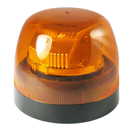
Overview Overview The SLR LED Rotator Beacon provides a reliable signal with three selectable RPM speeds. Models are available with flush or pipe mounting. The available colors are red and amber. The light can operate on a 12- or 24-volt power source. -
Page 9: Permanently Mounting The Beacon
Permanently Mounting the Beacon Table 1 Product Specifications Input Voltage 11 Vdc to 28 Vdc Nominal 12.8 Vdc or 25.6 Vdc Input Current, Amber 2 A at 12.8 Vdc pulsed, 0.8 avg. (nominal) 1 A at 25.6 Vdc pulsed, 0.4 avg. Flash Rate 90 RPM is the default pattern. -
Page 10: Figure 1 Permanent-Mounted Beacon With Wiring
Use installer-supplied #10-32 machine screws with #10 hex nuts and lockwashers. 6. Align the gasket over the drilled holes. Route the wires through the gasket and wire routing hole in the base and gasket. SLR LED Rotator Beacon Federal Signal www.fedsig.com... -
Page 11: Wiring The Permanently Mounted Beacon
Wiring the Permanently Mounted Beacon 7. Twist off the beacon dome from the base. 8. Secure the base to the mounting surface with the #10 Phillips pan-head thread-forming screws. Figure 2 Overhead view of mounting holes in the base REFLECTOR 290A6875 9. -
Page 12: Pipe-Mounting And Wiring The Beacon
6. Connect one terminal of the installer-supplied switch to the red (+) wire of the beacon. 7. Use minimum 18 AWG (1 mm ) wire to connect the remaining switch terminal to one end of the supplied fuseholder and 5 A fuse. SLR LED Rotator Beacon Federal Signal www.fedsig.com... -
Page 13: Selecting A Rotation Speed
Selecting a Rotation Speed 8. Connect the other end of the installer-supplied fuseholder to the positive (+) terminal of the voltage source. 9. Connect the black (–) wire from the beacon to a known good vehicle ground as close to the beacon as practical. Figure 3 Pipe-mounted beacon with wiring Beacon Black... -
Page 14: Figure 4 Location Of Rpm Jumper And Pins
290A6878 4. Lift the reflector from the beacon assembly and set it aside. The jumper pins are located between the optics ring and the motor on the connection side of the wire harness. SLR LED Rotator Beacon Federal Signal www.fedsig.com... - Page 15 Selecting a Rotation Speed 5. The default jumper setting of 90 RPM is a single-pin position, either the right or left pin. The settings for 75 RPM and 120 RPM are both two-pin positions. • To change the rotation speed to 75 RPM, pull the jumper straight up from the pin and place it on the right two pins.
-
Page 16: Maintaining The Beacon
Frequently inspect the beacon to ensure that it is securing attached to the vehicle and operates properly. Clean the beacon with a mild soap and a soft rag. SLR LED Rotator Beacon Federal Signal www.fedsig.com... -
Page 17: Getting Technical Support
Getting Technical Support Getting Technical Support For technical support, please contact: Federal Signal Corporation Phone: 1-800-443-9132 Fax: 1-800-343-9706 Email: empserviceinfo@fedsig.com Getting Repair Service The Federal Signal factory provides technical assistance with any problems that cannot be handled locally. Any units returned to returned to Federal Signal for service, inspection, or repair must be accompanied by a Return Material Authorization (RMA). -
Page 18: Ordering Replacement Parts
To order replacement parts, call Customer Support at 1-800-264- 3578, 7 a.m. to 5 p.m., Monday through Friday (CT) or contact your nearest distributor. Table 2 Replacement parts Description Part Number Dome, Red 8627205-04 Dome, Amber 8627205-02 Gasket, Mounting 8627319 SLR LED Rotator Beacon Federal Signal www.fedsig.com... -
Page 19: Figure 5 Template For Permanent Mounting (Not To Scale)
Ordering Replacement Parts Figure 5 Template for permanent mounting (Not to scale) IMPORTANT: Verify dimensions of mounting template. Ø 0.17 FOR TAPPED HOLES Ø 0.2 IN FOR CLEARANCE HOLES Ø 5.56 90° Ø 0.375 FOR CLEARANCE WIRE HARNESS HOLE Ø 0.17 IN FOR TAPPED HOLES Ø... - Page 20 2645 Federal Signal Drive University Park, Illinois 60484 www.fedsig.com Customer Support Police/Fire-EMS: 800-264-3578 • +1 708 534-3400 Work Truck: 800-824-0254 • +1 708 534-3400 Technical Support 800-433-9132 • +1 708 534-3400...
Need help?
Do you have a question about the SLR LED and is the answer not in the manual?
Questions and answers