Table of Contents
Advertisement
Quick Links
2562541A REV. A 1210
Safety Message to Installers of Federal Signal Warning Light Systems
People's lives depend on your proper installation and servicing of Federal Signal products. It is important to
read and follow all instructions shipped with this product and the original product. In addition, listed below are
some other important safety instructions and precautions you should follow:
•
To properly install a light assembly, you must have a good understanding of automotive electrical
procedures and systems, along with proficiency in the installation and use of safety warning equipment.
•
Frequently inspect the light system to ensure that it is operating properly and that it is securely attached
to the vehicle.
•
Always refer to the vehicle service manuals when performing equipment installations on a vehicle.
•
When drilling into a vehicle structure, be sure that both sides of the surface are clear of anything that
could be damaged.
•
Locate the light system controls so the VEHICLE and CONTROLS can be operated safely under all driving
conditions.
•
If a vehicle seat is temporarily removed, verify with the vehicle manufacturer if the seat needs to be
recalibrated for proper airbag deployment.
•
Do not install equipment or route wiring in the deployment path of an airbag. Failure to observe this
warning will reduce the effectiveness of the airbag or potentially dislodge the equipment, causing
serious injury to you or others.
•
To avoid damage to the lightbar, do not overtighten screws and nuts.
•
This product contains high intensity LED devices. To prevent permanent eye damage, DO NOT stare
into the light beam at close range.
•
For additional precautions and information, refer to the instructions packed with related products.
•
File these instructions in a safe place and refer to them when maintaining or reinstalling the product.
Failure to follow all safety precautions and instructions may result in property damage, serious injury, or death.
Introduction
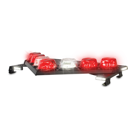
This publication provides instructions for installing the Vision™ SLR lightbar to a vehicle with the Hook-On
Mounting Kit. To complete the installation, it is necessary to purchase a vehicle-specific mounting hook kit.
Unpacking the Kit
After unpacking the kit, inspect it for damage that may have occurred in transit. If it has been damaged, file
a claim immediately with the carrier, stating the extent of damage. Carefully check all envelopes, shipping
labels, and tags before removing or destroying them. Ensure that the parts shown in Table 1 on page 2 are
contained in the packing carton. If you are missing any parts, contact Customer Support at 1-800-264-3578,
7 a.m. to 5 p.m., Monday through Friday (CT). Also required is an installer-supplied control head for
controlling the functions of the lightbar.
Installation Instructions for the Vision
Lightbar with the Hook-On Mounting Kit
SLR
™
Advertisement
Table of Contents

Subscribe to Our Youtube Channel
Related Manuals for Federal Signal Corporation Vision SLR


Summary of Contents for Federal Signal Corporation Vision SLR
- Page 1 Installation Instructions for the Vision ™ Lightbar with the Hook-On Mounting Kit 2562541A REV. A 1210 Safety Message to Installers of Federal Signal Warning Light Systems People’s lives depend on your proper installation and servicing of Federal Signal products. It is important to read and follow all instructions shipped with this product and the original product.
- Page 2 RH mounting foot is for the right side. Failure to follow this precaution may damage the lightbar. The Service Kit requires that you assemble the mounting feet on the lightbar. If you are installing a new lightbar, which is shipped with the mounting feet already attached, see “Installing the Adjustable Foot Brackets” on page 4. New lightbars may require that you loosen the 3/8"-16 nuts to adjust the positions of the mounting feet on the vehicle roof. To install the Service Kit mounting feet: 1. To avoid marring the plastic domes, invert the lightbar on soft rags or cardboard. 2. Use the four 3/8"-16 nuts and lockwashers to install a mounting foot assembly and a hook-attach bracket on the lightbar (Figure 1 on page 3). Tighten the nuts only enough to hold the mounting foot assembly in place. Vision SLR Lightbar...
- Page 3 (LEFT SIDE, INVERTED) 290A6429 3. Use a nut retainer and two #10 Type B pan Torx screws to trap the 5/16"-18 flange nut on the backside of the hook-attach bracket (Figure 2). 4. Repeat steps 2 and 3 with the other mounting foot assembly. 5. To continue with the installation, see “Installing the Adjustable Foot Brackets” on page 4. Figure 2 Hook-attach bracket installation HOOK ATTACH #10 TYPE B PAN BRACKET (2) TORX SCREWS (4) LH MOUNTING FOOT 5/15-18 FLANGE NUT (2) NUT RETAINER (2) 290A6430 Vision SLR Lightbar...
- Page 4 The adjustable foot brackets enable you mount the Vision SLR at the maximum height and to level the lightbar. To install the brackets: 1. To avoid marring the plastic domes, invert the lightbar on soft rags or cardboard. 2. See Figure 3. Use the 5/16"-18 pan Torx screws, 5/16" flat washers, and 5/16" lockwashers to install the adjustable foot brackets on the mounting feet. Figure 3 Adjustable foot bracket installation 5/16 WASHER (8) MOUNTING PAD (4) 5/16 LOCKWASHER (8) 5/16-18 PAN TORX SCREW (8) ADJUSTABLE FOOT BRACKET (4) LH MOUNTING FOOT 290A6431 Vision SLR Lightbar...
- Page 5 3. Center the lightbar assembly so that the end of the assembly and edge of the roof are equidistant on each side of the vehicle. Ensure that the gutter hooks, when installed, do not interfere with the door or door glass. Improper clamping on the vehicle roof may result if the gutter hooks contact the mounting feet. Adjust the mounting feet, if required, before tightening the 3/8"-16 hex nuts. 4. Remove the lightbar assembly from the vehicle roof and place it on soft rags or cardboard to avoid marring the plastic domes. 5. Turn the lightbar assembly over so that the bottom faces up. Tighten the eight 3/8"-16 nuts (four on each mounting foot) installed in “Installing the Service Kit Mounting Feet” on page 2. Hook-Mounting the Vision SLR on the Vehicle To mount the lightbar on the vehicle: 1. Place the lightbar assembly back into its original position on the vehicle roof. 2. To maximize aerodynamic efficiency, it is recommended that the lighting system be mounted as high as possible. Adjust the adjustable foot brackets on the mounting feet as required (Figure 4 on page 6). 3. Check to ensure that the lightbar assembly is level. If it is not level, adjust it by rotating it in the mounting foot slots. 4. See Figure 4 on page 6. Using the holes that are most closely aligned between the 5/16" Torx pan screws, install a #10 Type B pan Torx screw to lock in the adjustment. Minor adjustment may be necessary. Repeat this step for all four adjustable foot brackets.
- Page 6 Inverting and Aiming a Takedown Light Above the Mounting Foot To aim the LED takedown lights to the 45 degree or 90 degree position: 1. Cut the cable tie securing the connector to the underside of the foot and unplug the connector. 2. Remove the two 10-32 pan Torx screws and the takedown light. Install the split grommet over the cable, and feed the cable through the foot from the top. Install the grommet securely in the hole (Figure 6 on page 7). 4. Aim the LED takedown and install the 10-32 pan Torx screws from the bottom of the foot. 5. Reconnect the connector and secure it to the foot with the cable tie. 6. Test the light to verify that it operates properly. Vision SLR Lightbar...
- Page 7 #10-32 PAN TORX SCREWS LED TAKEDOWN LIGHT 290A6433 Figure 6 LED takedown light mounted above mounting foot LED TAKEDOWN LIGHT SPLIT GROMMET (2) 10-32 PAN TORX SCREW (4) 290A6438 Ordering Replacement Parts To order replacement parts, please contact your local dealer/distributor or: Customer Support Federal Signal Corporation Phone: 1-800-264-3578 7 a.m. to 5 p.m., Monday through Friday (CT) Vision SLR Lightbar...
- Page 8 Drop ship information as needed. • Any estimate required. When you receive your RMA Number: • Write the RMA number on the outside of the box of returned items. • Reference the RMA number on your paperwork inside of the box. • Write the RMA number down, so that you can easily check on status of the returned equipment. Send all material with the issued RMA Number to: Federal Signal Corporation 2645 Federal Signal Drive University Park, IL 60484-3167 Attn: Service Department RMA: #__________ 2645 Federal Signal Drive, University Park, IL 60484-3167 Tel.: (800) 264-3578 • Fax: (800) 682-8022 www.fedsig.com © 2010 Federal Signal Corporation Vision SLR Lightbar...
Need help?
Do you have a question about the Vision SLR and is the answer not in the manual?
Questions and answers