Advertisement
Quick Links
Advertisement

Related Manuals for Dancover Orangery GH170010


Summary of Contents for Dancover Orangery GH170010
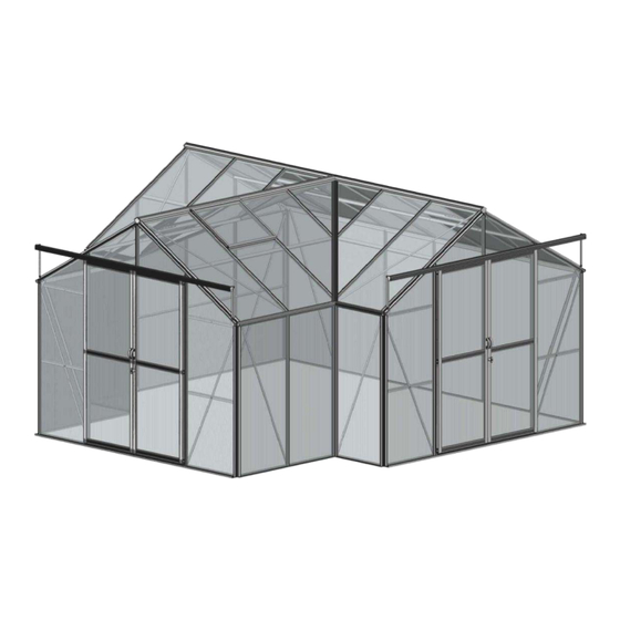
- Page 1 Manual Orangery 4,45x4,45x2,52m 07-05-2021...
- Page 2 Orangery Assembly Instructions —— For Sliding Door Walk-in Greenhouse...
- Page 3 Statement Dear Customer! May we congratulate you on buying new Greenhouse. We feel sure that by following the detailed assembly instructions, you will find as much pleasure in actually building the greenhouse as the many hours you will spend on your greenhouse in the future.
- Page 4 Cautions Please put on gloves avoid of slitting your hands. Avoid of crashing the material, results in un- shapes, it is not fits in fixture. Avoid of materials cuts the polycarbonates sheets. Tips The base has to be fastened in a non-freezing depth <80cm>. The greenhouse is to be fastened to the base.
- Page 5 Base Anchor Corner- Fixing M6x10 Base Base Base Base M6x10 Washer legs tabs Crop GTA10 1x4392 3x2958 2x747 2x1464...
- Page 6 Base IMPORTANT Before assembling aluminium base, the end trough centers of seven legs should match both end trough centers of side sills and front & rear sills at the same time. Please match seven cor- ner troughs together at the same time GTA10...
- Page 7 Front Gable 7001 7002 7003 7206 7268 7009 7211 7212 7015 7020 7021 Size 1600 2043 2043 2896 1656 1656 1712 1456 2856 G-m1 G-m2 G-p1 Size M6x10 M6x15 7211 7212 7206 7021 7020 7009 7009 7015 7015 7001 7002 7003 7001 7009...
- Page 8 Front Gable 7002 7001 7015 7268 7268 7015 7001 7009 7009 7002 7009 7211 7211 a1/a2 7001 7020 7020 7002 a1/a2 7020 G-m2 7009 Section View 7021 7015 7211 7212 7206 G-m1 7020 a1/a2 7206...
- Page 9 Rear Gable 7001 7002 7003 7207 7024 7210 7213 7214 7015 Size 1600 2043 2043 2436 2896 2884 1656 1656 1712 G-m1 G-m2 G-p1 Size M6x10 M6x15 7213 7214 7210 7015 7015 7001 7002 7207 7003 7001 7210 7024...
- Page 10 Rear Gable 7002 7001 7015 7024 7024 7207 7001 7210 7024 7002 7015 7210 7210 7213 G-m2 7210 7015 7001 7213 7214 7213 G-m1 a1/a2 a1/a2 7207 7002...
- Page 11 Side wall 7026 7029 7034 7036 7401 7402 7403 7404 7405 7406 7407 7408 7409 Size 4330 1732 4353 1600 1600 1433 1433 1458 1458 Size M6x10 M6x15 7034 7029 7029 7036 7036 7036 7036 7036 7026 7036 7034 7036 Note: Please add extra bolt into channel for eave 7026 cantilever use in advance.
- Page 12 Side wall a3/a2 7408 7409 7401 7404 7405...
- Page 13 Side wall Note: Bolts need to be slid into cor- ner bars for 7409 7408 eave canti- lever brac- 7409 7408 later. 7401 7401 a3/a2 7405 7404 7404 a3/a2 7405 a3/a2 7409 7029 7029 7036 7029 7029 7404 7405 7036 7408 7029 7408...
- Page 14 Roof 7412 7413 7415 7420 7421 7422 7423 7244 7045 7046 7049 7252 7427 Size 4353 2882 2222 1602 1602 1656 1449 2166 4317 1781 1769 7037 7251 Size M6x10 VERY IMPORTANT: Before attaching roof bars to structure, bolts will need to be slid into each roof bar for the ridge cantilever, two more for hanging basket rail, one more for the eave cantilever bracing between the roof and the side, one more for the vent slam bar attaching (If vent position to be decided).
- Page 15 Roof 7252 7252 7049 7244 7244 7244 7244 7244 7412 7423 7422 7421 7420 7045 7045 7422 7423 7427 7427 7415 7415 7420 7421 7046 7413 7046 7244 7244 7252 7252...
- Page 16 Roof 7412 7244 7034 7036 7244 7420 7412 7244 7252 7252 7427 7034 7036 7244 7049 7049 7415 7420 7421 7422 7423 7427 7045 7046 7415...
- Page 17 Roof 7420 7415 7421 7244 7244 7251 7244 7037 7037 7037 7036...
- Page 18 Vent 7053 7054 7055 7056 7057 7067 Φ3.9x8 M4x8 Size M6x10 7053 7244 7067 7053 7053 7244 7244 7054 7054 7056 7056 7056...
- Page 19 Vent 7055 7057 7055 7057 7055 7055 7056 p3/a4...
- Page 20 Door 7058 7059 7060 7061 7062 7063 7064 7065 G-p5 FLUFF M6x12 Φ6 Φ3.5x19 Size 1938 1938 1938 715 M6x10 M6 1938 7061 7061 7059 7058 7058 7060 7059 7058 7063 7063 7063 7062 7062 7058 7061 7058 7063 7058 7062...
- Page 21 Door 7065 a15/a16/a2 a15 round head M6x16 door stop bolt and gasket should be fixed in center door track rail. G-p5 7021 7021 7064 7064...
- Page 22 4mm Glass Note: Please loose glazing bar #7423 & #7422 before inserting “V” panel into Alu. Profile channel. 7423 7422 7423 7422 Note: PVC capping bars were pushed in place from both top and bottom in diagonal direction together. If you assemble it from one side by one side, you will fell space is too tight to assemble another PVC capping bar.
- Page 23 4mm Glass Side c-1599 c-1599 c-2030 c-2030 c-2043 c-2436 c-2436 c-2043 c-2030 c-2030 Roof c-1599 c-1599 Rear Front Side Side Roof c-747 c-747 c-747 c-759 c-759 Side Side c-1575 c-1575 c-955 c-955 c-1599 c-1599 c-1599 c-1026 c-1026 c-1599 c-1599 c-1655 c-1655 c-1599 c-1655...
- Page 24 4mm Glass Length GTA10 Size GTA10 700 x 35 / 438 Front 650 x 933 Gable 1599 700 x 1597 2030 700 x 631 700 x 448 / 852 1599 700 x 61 / 465 Rear 2030 Gable 700 x 1666 2043 2436 700 x 1037...
- Page 25 PVC Capping Bar Please trim vertical PVC capping bar which ex- ceeding Alu. Profile. Sliding slope PVC cap- ping bar into Alu. Profile gap. Two slope PVC capping bar connect together with- out gap. Please trim two slope PVC capping bar edge on top end and make them connect without gap.
- Page 26 Downpipe a8/a2 15mm 1000 M6x16...
- Page 27 The list of parts Description Front gable Rear gable Side wall Roof Vent Door Base connector Glass panels Tools Assembly Instruction...
- Page 28 Head office: Dancover A/S For more information Lyngevej 16A, Nørre Herlev please visit: 3400 Hillerød www.dancovershop.com Denmark...
Need help?
Do you have a question about the Orangery GH170010 and is the answer not in the manual?
Questions and answers