Table of Contents
Advertisement
Quick Links
Advertisement
Table of Contents

Subscribe to Our Youtube Channel
Related Manuals for Dancover GH170090


Summary of Contents for Dancover GH170090
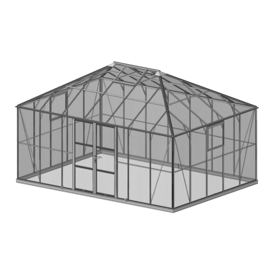
- Page 1 Manual Greenhouse 5,14x3,71x3,15m 03-11-2023...
- Page 2 Greenhouse Assembly Instructions —— For Hinged Door Walk-in Greenhouse...
- Page 3 Thank you for purchasing your new greenhouse. We recommend you familiarize yourself with the instructions and read all safety information before you commence assembly. These instructions are divided into sections: Base, Part lists, Preparation, Side wall, Rear wall, Front wall, Roof, Vent, Door, PVC capping bar, Glass, Down pipes, Optional Turbine Vent, Anchoring greenhouse to slab or base etc.
- Page 4 And for GH170090 model, some extra long parts like gutter, sill bar (base) and rear horizontal bracing bar were packed in specific package.
- Page 5 If you use supplier's original chamber box section alu. base, also recommended. Gable Side Anchor Fixing M6x10 profiles profiles Cornerite M6x10 Washer legs tabs Crop (mm) (mm) GH170090 2x5109 2x3675 Gable Side Base on grass On brick without base...
- Page 6 Before assembling aluminium base, the end trough centers of four legs should match both end trough centers of side sills and front & rear sills at the same time. Please match four corner troughs together at the same time GH170090...
-
Page 7: Table Of Contents
Parts List Package 1 Side wall 7601 7025 9307 7607 9317 7910 7037 Size 1922 3613 3707 1922 3601 2033 M6x10 M6x15 Package 2 Rear wall 9311 9310 7607 9319 7910 7037 Size 5047 5141 1922 5035 2033 M6x10 M6x15 Package 3 Front wall 9314 9309 7607 7530 9323 7910 7037... -
Page 8: Parts List
Parts List Package 6 Door 7523 7524 7525 7526 7527 7961 7529 Φ3.5x19 M6x25 Size 1909 1909 1909 M6x10 S1/S2 LOCK Rubber Fluff Φ3.5x13 Size M6x8 2 SETS 1 SET 1.4M Package 8 Downpipe Φ3.5x13 1400 Package 9 Roof Vent 7053 7054 7055... - Page 9 BASE Base dimensions and recommendations. Ensure that your base is level as this will make assembly of the building, especially the glazing of the roof much more straight forward. PARTS LIST Most components should have a code punched into their metal surface. Identify and separate all like for like components prior to assembly.
- Page 10 Connect roof glazing bar to roof corner bar with joining plate #m3. Join 8 short roof glazing bar #9334 & #9335 between roof corner bar and eave. Join 8 long roof glazing bar #9338 & #9339 between roof corner bar and eave. Note: ---Please remember to insert an extra bolt in roof short glazing bar(#9334,#9335) in advance for cantilever #7037 use.
-
Page 11: Size M6X10 M6X15
Package 1 Side wall 7601 7025 9307 7607 9317 7910 7037 Size 1922 3613 3707 1922 3601 2033 M6x10 M6x15 9307 7910 7910 9317 7601 7607 7607 7607 7607 7601 7025 7607 7601 7910 7025 7025... - Page 12 Side wall 7607 7025 7910 7607 7601 9317 9317 9317 9307 9307 7601 7601 7910 Note: Please add ex- 9307 tra bolt into channel for cantilever use in advance. 7607 Note: At this stage, if you already decide where your side vent are positioned, please insert two extra bolts into each side bar (#7607) either side of a vent opening.
-
Page 13: Size M6X10 M6X15
Package 2 Rear wall 9311 9310 7607 9319 7910 7037 Size 5047 5141 1922 5035 2033 M6x10 M6x15 9310 7607 7607 7607 7607 7607 7607 7910 7910 9319 9311 7607 7607 7910 9311 9311 7910 7607 9310 9310 9319 9319 7607 7910 Note: Please add extra... -
Page 14: Rubber
Package 3 Front wall 9314 9309 7607 7530 9323 7910 7037 Rubber Size 5047 5141 1922 1922 1809 2033 464 M6x10 M6 M6x15 M6x8 9309 7607 7607 7530 7530 7607 7607 7910 7910 9323 9323 9314 7530 7530 Rubber 7530 7530 7530 a19/a2... - Page 15 Front wall 7530 7607 7910 9314 9314 7910 7607 7530 9309 9323 9323 9323 7910 9309 9309 7530 7607 Note: Please add ex- tra bolt into channel for cantilever use in advance.
- Page 16 Connect side wall with front wall and rear wall 9310 9319 a3/a2 9311...
-
Page 17: 9365 9366 M3 A1 A2 A20 A5 A18 P14
Package 4 Roof 9333 9334 9335 9338 9339 7344 9342 9347 9326 7351 9363 9364 Size 2684 1642 1642 2070 1890 3324 1496 9365 9366 Φ3.5x19 Φ3.5x13 Size M6x10 9326 9326 9363 9364 9363... - Page 18 Roof 7344 7344 7344 9326 7344 7344 7344 9333 9333 9333 9326 9333 9326 9333 9333 9333 9333 9333...
- Page 19 Roof 9334 9338 9339 9335 9335 9334 9347 7344 7344 9338 9339 9342 9342 9339 9338 7344 7344 9335 9347 9334 9335 9339 9338 9334 9333 9333 9333 9333 9342/ 9342/ 9347 9334/ 9347 9334/ 9338 9338 7344 7344 7037 9342/ 7351 9338/...
- Page 20 Roof 9366 9365...
-
Page 21: Size 730 739 718 701 592 300 - M6X10 M6 Φ3.9X8 M4X8 M4
Package 5 Side Vent 7870 7053 7874 7055 7056 7057 M6x10 M6 Φ3.9x8 M4x8 Size 7870 No gap No gap 7053 7053 a1/a2 7874 7874 7056 7056 7056... - Page 22 Side Vent 7055 7057 7055 7057 7055 7055 7056 p3/a4...
-
Page 23: Qty
Package 9 Roof Vent 7053 7054 7055 7056 7057 Φ3.9x8 M4x8 Size M6x10 7053 7344 7344 7053 7344 7054 7054 7056 7056 7056... - Page 24 Roof Vent 7055 7057 7055 7057 7055 7055 7056 p3/a4...
-
Page 25: Qty
Package 6 Door 7523 7524 7525 7526 7527 7961 7529 Φ3.5x19 M6x25 Size 1909 1909 1909 M6x10 S1/S2 LOCK Rubber Fluff Φ3.5x13 Size M6x8 2 SETS 1 SET 1.4M 7524 7524 7525 7525 7525 7525 7527 7961 7526 7527 7523 7523... - Page 26 Door 7526 Φ3.5x19 M4x28 M4x40 a11/a2 7527 7523 7523 First take off the cap of S1 by rotating the cap anticlockwise, then fix the cap with a11 to #7520, finally rotate S1 back to the cap. 7961 7529 a19/a2 7526/ 7527 7527 7524...
- Page 27 Door 7525 a19/a2 7527 7523 7527 7523 a19/a2 7524 a19/a2 7961 7961 a19/a2 7523 Rubber...
- Page 28 Door a9/a2...
- Page 29 PVC Capping Bar Step1 Step6 Step3 Step4 Step5 Step2 PVC Capping Bar Note: PVC capping bars were pushed in place from both top and bottom in diagonal direction together. If you assemble it from one side by one side, you will fell space is too tight to assemble another PVC capping bar.
- Page 30 4mm Glass...
- Page 31 4mm Glass If you feel PVC Push on size not cor- rect, please use scissors to cut it. c-787 c-787 c-813 c-813 c-1615 c-1615 c-1641 c-1641 c-1641 c-1641 c-1615 c-1615 c-813 c-813 c-787 c-787...
- Page 32 4mm Glass DWG Length QTY Size 1921 700x1919 Side 1243 603x609 700x631 341x1919 700x1248 695x0/802 1060 700x822/1630 Roof 1095 700x1007 1615 700x642/1017/642x50 1641 700x642/1072x327 2069 700x1451 1439 5 meter 34 roll Silicone Glass Glass Glass...
- Page 33 Downpipe Waterproof Alu. Foil tape 100mm x 4pc Φ3.5x13 1400...
- Page 34 Optional Cresting and Finials Please use silicone to fix the crestings and finials on ridge. CAUTION: Fill in gap Once finial in position, please im- mediately drill a 4mm hole on ridge finial with M4x12 bolt and M4x12 nut to avoid finial falling off to injure people.
- Page 35 The list of parts GH170090 Description Side wall Rear wall Front wall Roof Side Vent Door PVC capping bar Downpipe Roof Vent Glass Tools Assembly Instruction...
- Page 36 Contact information Austria Belgium Croatia Denmark Estonia Finland France Germany Ireland Italy Latvia Lithuania Nederland Norway Poland Portugal Spain Sweden Switzerland For more information please visit: www.dancovershop.com...
Need help?
Do you have a question about the GH170090 and is the answer not in the manual?
Questions and answers