Table of Contents
Advertisement
TORNADO INDUSTRIES, LLC
3101 WICHITA COURT
FORT WORTH, TX 76140
PHONE 800-VACUUMS
FAX 817-551-0719
WWW.TORNADOVAC.COM
Operations & Maintenance Manual
For Commercial Use Only
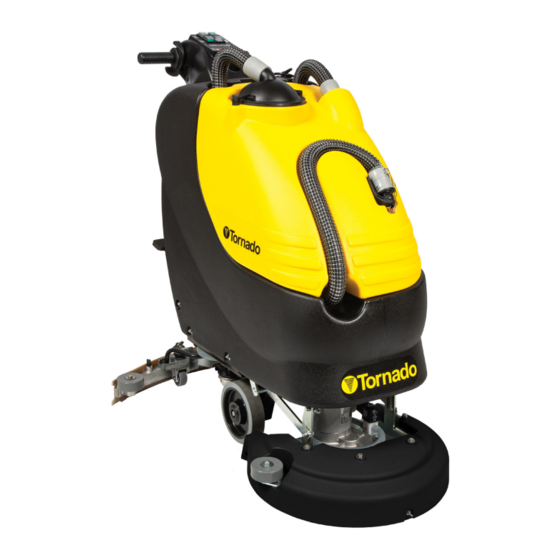
AUTOMATIC SCRUBBER
MODEL NO: TS120-S45-U
Form No. T-OM680L 05/2021 ©Tornado Industries, LLC. All rights reserved
Save These Instructions
Advertisement
Table of Contents


Need help?
Do you have a question about the BD 20/11L and is the answer not in the manual?
Questions and answers