Table of Contents
Advertisement
Quick Links
Advertisement
Table of Contents

Related Manuals for Challenge MS-10


Summary of Contents for Challenge MS-10
- Page 1 Challenge MS-10 Multi- Spindle Paper Drill Instruction Manual...
- Page 2 Products may be unsupported by The Challenge Machinery Company due to age or the unavailability of parts from their original manufacturer. No parts or product support will be available to repair or maintain unsupported products.
-
Page 3: Introduction
Also be sure to fill out the warranty card accompanying your machine and return it DIRECTLY TO CHALLENGE. If you bought a used machine, it is important to have the following information on record at Challenge. Copy this page, fill in the information and send it care of The Challenge Service Department, 6125 Norton Center Drive ... -
Page 4: Table Of Contents
7.7 TOOL STORAGE ........................19 7.8 DRILLING TIPS ......................... 19 7.9 Routine Maintenance ......................... 21 8.0 Accessories ............................ 22 8.1 Genuine Challenge Hollow Drills ....................22 8.2 Drill Ease ........................... 22 8.3 Challenge Drilling Blocks ......................22 8.4 Hollow Drill Hand Sharpener ..................... 23 8.5 Handy - Sharp - Hollow Drill Sharpener ................... -
Page 5: Safety
If the machine sounds or operates abnormally, turn it off and have it checked by a qualified service person or your Authorized Challenge Dealer. CRUSH HAZARD, keep feet off the pedal when handling paper under the pressure feet. DO NOT REST FOOT ON PEDAL at any time! ... -
Page 6: Warning Label Definitions
2.0 Safety 2.3 Warning Label Definitions The following warning labels are found at various locations on your machine. Read and understand the meaning of each symbol. If a label is lost from the machine, it should be replaced. The item number and location of each label can be found in Section 17.0, Schematics and Parts List. -
Page 7: Specifications
See Options for Large Hole Drilling and Triple Drill Head for drilling 3 holes on 1” Centers Challenge reserves the right to make changes to any product or specification without notice and without incurring responsibility to existing units. -
Page 8: Packing List
4.0 Packing List 4.0 Packing List Part No. Description Qty. Basic Machine A-4950-2 Hand Drill Sharpener / Chip Remover A-6626 Wood Drill Blocks A-6588 T- Handle Drill Drift S-1718 Grease Gun 4688 Lubrication Stick 5064 Drilling Block Hook 6563-2 Filler Block H-6955-506 Thumb Screws for Filler Blocks 6614... -
Page 9: Options
5.0 Options 5.0 Options Standard Drilling Head – P/N A-6594-6 Capacity is 2-1/2”/6.4cm. One 1/4” & one 5/16” hollow drill included with each head. (Can also be used with 2” hollow drills) Triple Drilling Head – P/N A3-6594-5 Drills three holes at once on 1” Centers. Capacity is 2-1/2”/6.4cm. -
Page 10: Drill Head Configurations
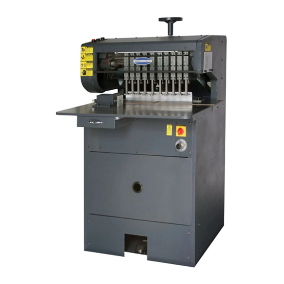
5.0 Options 5.1 Drill Head Configurations... - Page 11 5.0 Options Drill Depth Adjustment Handwheel Start/Stop and Table Lite Push Buttons Drive Spline Shield Access Window Drive Spline Backgauge Lock Drill Heads Knob Side Guide Backgauge Main disconnect switch Speed Control Tool Drawer Electrical Chip Drawer Panel Access Cover Foot Pedal MS-10B DRILL...
-
Page 12: Installation Guide
Test your voltage when the shop is at actual working levels. Challenge recommends a dedicated line with a lockable disconnect to provide adequate power for this machine. -
Page 13: Three Phase Hook-Up
6.0 Installation Guide 6.2.1 Three Phase Hook-Up 1. Disconnect the power at the main power panel and lock it out to prevent accidental power-up. See Power Lock-Out procedure, page 4. 2. Thread the power cord through the knock-out hole in the junction box located on the left hand side of the machine. -
Page 14: Controls
6.0 Installation Guide 6.3 Controls The control panel is mounted on the top left of the machine. The blue TABLE LIGHT push button turns the table light on and off. The green START push button turns the spindle and pump motors on. The red STOP push button will shut both motors off. -
Page 15: Drill Blocks
6.0 Installation Guide 6.5.1 Drill Blocks The wood blocks are inserted in the table slot as shown in Figure 3. The blocks should be flush with the table top, shim if necessary. The blocks can be turned around and over when worn. Figure 3 6.5.2 Mounting Drill Heads The drill heads are inserted as follows:... - Page 16 6.0 Installation Guide 2. Rotate the spindle lock knob until the cut out in the knob aligns with the pin in the spline shaft and pull the shaft out. (See Figure 5 & Figure 6,below) Spline shaft lock Spline shaft knob.
-
Page 17: Mounting The Side Guide
6.0 Installation Guide Swing the front cover back unit it rests on top of the machine. Loosen the drill head clamp located on the back of the drill head. Place the head on the dovetail of the drill and slightly tighten the clamp screw. -
Page 18: Installing/Removing The Hollow Drills
6.0 Installation Guide 6.5.4 Installing/Removing the Hollow Drills Always handle drills with care to avoid servere lacerations. Even dull drills are sharp enough to cause lacerations. TO INSTALL : Insert the tapered head of the hollow drill into the spindle. Press the drills firmly into place so they do not fall out when the machine is started. -
Page 19: Operation
7.0 Operation 7.0 Operation 7.1 STARTING THE MACHINE Two motors supply the power to the machine: one is for the hydraulic pump, the other is for driving the drill spindles. Both motors are simultaneously controlled by the start and stop buttons located on the top left of the machine. -
Page 20: Positioning The Drill Heads
7.0 Operation Adjust the handwheel on the top of the machine clockwise until one drill bit starts to drill through. Next, adjust the remaining drills individually with the adjusting knob on top of each drill head until all of the drills just cut through the sample. It may be necessary to adjust the handwheel slightly when drilling a full lift of stock. - Page 21 Challenge. The Challenge Machinery Company assumes no liability for any modification or alteration to any Challenge products, and The Challenge Machinery Company does not authorize any such modification or alteration to any Challenge products. Any...
-
Page 22: Routine Maintenance
7.0 Operation 7.9 Routine Maintenance General Production losses can be reduced if good maintenance practices are followed. The following suggestions may be helpful: 1. Recognize the fact that the user of hydraulic equipment has more control over maintenance than the manufacturer. 2. -
Page 23: Accessories
It eliminates binding and excessive heating of the drill. Will not discolor the stock. CARE MUST ALWAYS BE TAKEN WHEN USING STICK AND HANDLING DRILLS. 8.3 Challenge Drilling Blocks Cat. No. A-6626-24 These Challenge 1x6” / (3 x15 cm) wood drilling blocks are for round hole drilling operations. Sold in packages of 24. -
Page 24: Hollow Drill Hand Sharpener
This Challenge Hollow Drill Sharpener can pay for itself many times over through longer drill life, easier, faster drilling, and less sharpening time. All sizes of drills from 1/8 to 1/2 inch in diameter can be sharpened. -
Page 25: Handy - Sharp - Hollow Drill Sharpener
8.0 Accessories 8.5 Handy - Sharp - Hollow Drill Sharpener Catalog No. 57100 Features: Spring- loaded pressure prevents flaring the end of the hollow drill bit. Light and portable, easy to use. Clamps onto a bench or table. ... -
Page 26: Two Hand Push Button Control
8.0 Accessories 8.6 Two Hand Push Button Control Catalog No. A-4851-51 This 2-hand control safety kit can be installed on the MS-10B in place of the standard foot pedal control. All of the necessary hardware and instructions are included in the kit. The 2-hand control offers anti- tie down and anti-repeat features, which means both buttons must be released between each cycle, and both buttons must be pressed within .5 seconds of each other. -
Page 27: Fiber Cutting Blocks
8.0 Accessories 8.10 Fiber Cutting Blocks Catalog No. A-12607 These are recommended for use with the Cornermatic Round Cornering Attachment. 8.11 Plastic Drilling Blocks Catalog No. 6669 Used for large hole drilling only. 2-1/4" X 6"/( 57/ 152cm) 8.12 Automatic Trip Side Guide Catalog No. -
Page 28: Rykon 100 Hydraulic Oil
8.0 Accessories 8.18 Rykon 100 Hydraulic Oil quarts) Available in 5 gallon container only. Catalog No. S-1991-4 (Capacity 1-1/2 8.19 Large Hole Hollow Drill bits 2"/51 mm drilling capacity. For use with large hole drilling head only. Sizes other than those listed, available on special order. - Page 29 F.399-DO August 2015...
Need help?
Do you have a question about the MS-10 and is the answer not in the manual?
Questions and answers