Table of Contents
Advertisement
Quick Links
GETTING STARTED GUIDE
PXIe-5667 (7 GHz)
Vector Signal Analyzer
Note
Before you begin, install and configure your chassis and controller.
This document explains how to install, configure, and test the PXIe-5667. The PXIe-5667 is a
modular vector signal analyzer. The PXIe-5667 ships with the NI-RFSA instrument driver,
which you use to program the device.
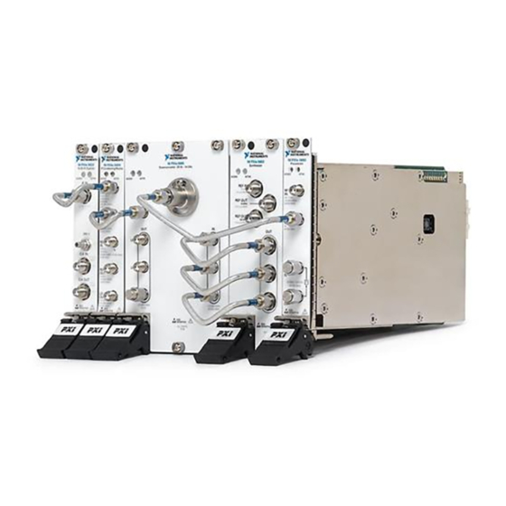
The PXIe-5667 comprises the following devices:
•
PXIe-5605 RF downconverter module
•
PXIe-5622 IF digitizer module
•
PXIe-5653 LO source module
•
PXIe-5693 RF preselector module
•
PXIe-5694 IF conditioning module
Caution
manner not described in this document.
Hot Surface
temperatures and cause burns. Allow the PXIe-5667 to cool before removing it from
the chassis.
Contents
Electromagnetic Compatibility Guidelines............................................................................... 2
Verifying the System Requirements..........................................................................................2
Unpacking the Kit..................................................................................................................... 2
Verifying the Kit Contents................................................................................................ 4
Preparing the Environment....................................................................................................... 5
Installing the Software.............................................................................................................. 5
Installing the PXIe-5667........................................................................................................... 6
Interconnecting the PXIe-5667 Modules.......................................................................... 7
Configuring the PXIe-5667 in MAX...................................................................................... 24
Self-Calibration....................................................................................................................... 25
Performing a Device Self-Calibration Using the NI-RFSA SFP.................................... 26
Programming the PXIe-5667.................................................................................................. 27
NI-RFSA Examples........................................................................................................ 29
The protection provided by this product may be impaired if it is used in a
If the PXIe-5667 has been in use, it may exceed safe handling
Advertisement
Table of Contents

Related Manuals for National Instruments PXIe-5667


Summary of Contents for National Instruments PXIe-5667
-
Page 1: Table Of Contents
Note Before you begin, install and configure your chassis and controller. This document explains how to install, configure, and test the PXIe-5667. The PXIe-5667 is a modular vector signal analyzer. The PXIe-5667 ships with the NI-RFSA instrument driver, which you use to program the device. -
Page 2: Electromagnetic Compatibility Guidelines
Furthermore, any modifications to the product not expressly approved by National Instruments could void your authority to operate it under your local regulatory rules. - Page 3 Do not install a device if it appears damaged in any way. Unpack any other items and documentation from the kit. Store the device in the antistatic package when the device is not in use. PXIe-5667 (7 GHz) Getting Started Guide | © National Instruments | 3...
-
Page 4: Verifying The Kit Contents
8. Long, Dark Blue Flexible RF SMA-to-SMA Cable, 17. PXIe-5667 7 GHz Vector Signal Analyzer Getting Part Number 763187-08 Started Guide (This Document) 9. Flexible, 7-Inch, RF SMA-to-SMA Cable (x2), Part Number 763282-07 4 | ni.com | PXIe-5667 (7 GHz) Getting Started Guide... -
Page 5: Preparing The Environment
Optional Items • A 1 N · m standard SMA torque wrench (NI part number 780487-01). Preparing the Environment Ensure that the environment you are using the PXIe-5667 in meets the following specifications. Operating ambient temperature 0 °C to 55 °C... -
Page 6: Installing The Pxie-5667
Installing the PXIe-5667 Caution To prevent damage to the PXIe-5667 caused by ESD or contamination, handle the module using the edges or the metal bracket. You must install NI-RFSA before installing the hardware. Before you install the hardware, refer to the guidelines in the Maintain Forced-Air Cooling Note to Users included with the module to ensure that the device can cool itself effectively. -
Page 7: Interconnecting The Pxie-5667 Modules
PXIe-5667 modules can be placed in PXI Express peripheral slots, PXI Express hybrid peripheral slots, or PXI Express system timing slots. Touch any metal part of the chassis to discharge static electricity. Ensure that the ejector handle is in the downward (unlatched) position. - Page 8 ESD prevention measures during installation, maintenance, and operation. Figure 3. Installation of Included PXIe-5667 Cables and Termination Loads NI PXIe-5693 NI PXIe- 5622 NI PXIe- 5694 NI PXIe-5605 NI PXIe-5653 16-Bit IF Digitizer IF Conditioning Module...
- Page 9 Refer to the NI RF Vector Signal Analyzers Help for information about how to connect the PXIe-5667 using an external clock or how to connect multiple PXIe-5667 modules. Direct Connections to the PXIe-5605 The PXIe-5605 is a precision RF instrument that is sensitive to ESD and transients. Ensure you are making proper direct connections to the PXIe-5605 to avoid damaging the device.
- Page 10 The signal pins of this product's input/output ports can be damaged if subjected to ESD. To prevent damage, turn off power to the product before connecting cables and employ industry-standard ESD prevention measures during installation, maintenance, and operation. 10 | ni.com | PXIe-5667 (7 GHz) Getting Started Guide...
- Page 11 This connector is the output terminal for the frequency-translated IF signal. The IF OUT connector is rated at +22 dBm maximum, 0 VDC. The maximum safe voltage is 24 VDC. PXIe-5667 (7 GHz) Getting Started Guide | © National Instruments | 11...
- Page 12 +15 dBm. The maximum safe voltage is 25 VDC. Note LO1 OUT, LO2 OUT, and LO3 OUT enable phase-coherent operation of multiple devices by allowing you to use common LO signals when daisy-chaining 12 | ni.com | PXIe-5667 (7 GHz) Getting Started Guide...
- Page 13 If the power supply fails, contact NI technical support. PXIe-5667 (7 GHz) Getting Started Guide | © National Instruments | 13...
- Page 14 Figure 5. PXIe-5622 IF Digitizer Module Front Panel 16-Bit IF Digitizer ACCESS ACTIVE IF IN + 20 dBm MAX 50 Ω PFI 1 CLK IN 6.3 Vp-p 50 Ω CLK OUT 2 Vp-p 50 Ω SENSITIVE 14 | ni.com | PXIe-5667 (7 GHz) Getting Started Guide...
- Page 15 IF IN is an SMA connector with an input impedance of 50 Ω (nominal). When used in a PXIe-5667 the IF IN connector has a +4 dBm full- scale input level and a -6 dBm input level (nominal). The maximum input level is +20 dBm or damage can occur.
- Page 16 RED—The module has detected an error. NI-RFSA must access the module to determine the cause of the error. The LED remains red until the error condition is removed. 16 | ni.com | PXIe-5667 (7 GHz) Getting Started Guide...
- Page 17 10 MHz 1.5 V p-p MAX REF OUT 100 MHz 1.5 V p-p MAX 800 MHz 4 GHz 3.2 GHz - 8.3 GHz SENSITIVE ALL PORTS 50 Ω PXIe-5667 (7 GHz) Getting Started Guide | © National Instruments | 17...
- Page 18 Connects to the LO3 IN connector on the PXIe-5605 module front panel. This connector is the output terminal for the LO3 (800 MHz) source. LO3 OUT is an SMA connector with an impedance of 50 Ω (nominal). 18 | ni.com | PXIe-5667 (7 GHz) Getting Started Guide...
- Page 19 The PXIe-5653 LO source has 10 MHz and 100 MHz reference outputs. For best performance, connect the 100 MHz REF OUT connector to the PXIe-5622 CLK IN connector. PXIe-5667 (7 GHz) Getting Started Guide | © National Instruments | 19...
- Page 20 The signal pins of this product's input/output ports can be damaged if subjected to ESD. To prevent damage, turn off power to the product before connecting cables and employ industry-standard ESD prevention measures during installation, maintenance, and operation. 20 | ni.com | PXIe-5667 (7 GHz) Getting Started Guide...
- Page 21 If the power supply fails, contact NI technical support. PXIe-5667 (7 GHz) Getting Started Guide | © National Instruments | 21...
- Page 22 The signal pins of this product's input/output ports can be damaged if subjected to ESD. To prevent damage, turn off power to the product before connecting cables and employ industry-standard ESD prevention measures during installation, maintenance, and operation. 22 | ni.com | PXIe-5667 (7 GHz) Getting Started Guide...
- Page 23 Output terminal for a 10 MHz signal received at the REF/LO IN connector. LO OUT Output terminal for either a 215 MHz LO signal received at the REF/LO IN connector or an internally generated 215 MHz LO signal. PXIe-5667 (7 GHz) Getting Started Guide | © National Instruments | 23...
-
Page 24: Configuring The Pxie-5667 In Max
In the configuration tree, expand Devices and Interfaces to see the list of installed NI hardware. Note If you are using the PXIe-5667 with the LabVIEW Real-Time Module, expand Remote Systems. Find your target IP address or name, expand it, and then expand Devices and Interfaces. -
Page 25: Self-Calibration
In the Associated Devices section, select the appropriate module from each system component drop-down listbox. For the PXIe-5667, you must associate the PXIe-5622 IF digitizer module, the PXIe-5653 LO source module, the PXIe-5693 RF preselector module, and the PXIe-5694 IF conditioning module. -
Page 26: Performing A Device Self-Calibration Using The Ni-Rfsa Sfp
Launch the NI-RFSA SFP by navigating to Start»All Programs»National Instruments»NI-RFSA»NI-RFSA Soft Front Panel. Click Device/System»Calibration»Self Calibration. Select the self-calibration steps you want to perform from the Self-Calibration dialog box. Click Next to run the self-calibration. 26 | ni.com | PXIe-5667 (7 GHz) Getting Started Guide... -
Page 27: Programming The Pxie-5667
Programming the PXIe-5667 You can acquire data interactively using the NI-RFSA Soft Front Panel (SFP) or use NI-RFSA to program your device in the ADE of your choice. PXIe-5667 (7 GHz) Getting Started Guide | © National Instruments | 27... - Page 28 Refer to the Creating an Application with Microsoft Visual C and C++ topic of the NI RF Vector Signal Analyzers Help if you prefer to manually add all required include and library files to the project. 28 | ni.com | PXIe-5667 (7 GHz) Getting Started Guide...
-
Page 29: Ni-Rfsa Examples
Disconnect any signals from the module front panels. Power off the chassis. Remove the module from the chassis and inspect it for damage. Do not reinstall a damaged device. PXIe-5667 (7 GHz) Getting Started Guide | © National Instruments | 29... -
Page 30: Configuration
What Should I Do if the Device Does Not Initialize? Failure to initialize may indicate a problem with module interconnections or with MAX. If the niRFSA Initialize VI or the niRFSA_init function returns an error and the PXIe-5667 fails to initialize, complete the following steps: Reconnect the PXIe-5667 hardware module front panel cables securely. -
Page 31: Measurements
What Should I Do if the Device Amplitude Reading Does Not Match the Source? Verify that the discrepancy between the PXIe-5667 and the source is within the error limits of the devices. Verify the absolute amplitude accuracy of the PXIe-5667 using the appropriate value. -
Page 32: Where To Go Next
The NI website is your complete resource for technical support. At ni.com/support, you have access to everything from troubleshooting and application development self-help resources to email and phone assistance from NI Application Engineers. 32 | ni.com | PXIe-5667 (7 GHz) Getting Started Guide... - Page 33 United States, visit the Worldwide Offices section of ni.com/ niglobal to access the branch office websites, which provide up-to-date contact information, support phone numbers, email addresses, and current events. PXIe-5667 (7 GHz) Getting Started Guide | © National Instruments | 33...
- Page 34 NI trademarks. Other product and company names mentioned herein are trademarks or trade names of their respective companies. For patents covering NI products/technology, refer to the appropriate location: Help»Patents in your software, the file on your media, or the National Instruments Patent Notice at . You can find patents.txt ni.com/patents...
Need help?
Do you have a question about the PXIe-5667 and is the answer not in the manual?
Questions and answers