Table of Contents
Advertisement
GETTING STARTED GUIDE
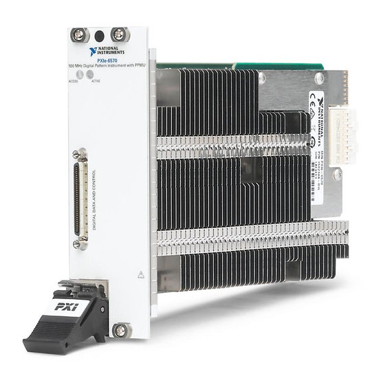
PXIe-6570
32-Channel Digital Pattern Instrument
Note
Before you begin, install and configure your chassis and controller.
This document explains how to install, configure, and test the PXIe-6570. The PXIe-6570 is a
32-channel digital pattern instrument.
Caution
a manner not described in this document.
Contents
Electromagnetic Compatibility Guidelines............................................................................... 2
Verifying the System Requirements..........................................................................................2
Unpacking the Kit..................................................................................................................... 2
Kit Contents...................................................................................................................... 3
Preparing the Environment....................................................................................................... 3
Installing the Software.............................................................................................................. 3
Digital Pattern Editor........................................................................................................ 4
NI-Digital Pattern Driver.................................................................................................. 4
Associated Drivers............................................................................................................ 5
Installing the PXIe-6570........................................................................................................... 5
Connecting Signals................................................................................................................... 7
PXIe-6570 Front Panel......................................................................................................7
Connecting to a Device Under Test.................................................................................. 9
PXIe-6570 Accessories................................................................................................... 10
Configuring the PXIe-6570 in MAX...................................................................................... 11
Operating the Digital Pattern Instrument................................................................................ 11
Digital Pattern Instrument Examples.............................................................................. 12
Troubleshooting...................................................................................................................... 13
What Should I Do if the PXIe-6570 Doesn't Appear in MAX?......................................13
What Should I Do if the Module Fails the Self-Test?.....................................................13
Why Is the ACCESS LED Off When the Chassis Is On?...............................................14
Where to Go Next................................................................................................................... 15
Worldwide Support and Services............................................................................................ 15
You can impair the protection provided by the PXIe-6570 if you use it in
Advertisement
Table of Contents

Related Manuals for National Instruments PXIe-6570


Summary of Contents for National Instruments PXIe-6570
-
Page 1: Table Of Contents
32-Channel Digital Pattern Instrument Note Before you begin, install and configure your chassis and controller. This document explains how to install, configure, and test the PXIe-6570. The PXIe-6570 is a 32-channel digital pattern instrument. Caution You can impair the protection provided by the PXIe-6570 if you use it in a manner not described in this document. -
Page 2: Electromagnetic Compatibility Guidelines
Caution To ensure the specified EMC performance, you must install PXI EMC Filler Panels, National Instruments part number 778700-01, in all open chassis slots. Verifying the System Requirements To use the NI-Digital Pattern Driver and Digital Pattern Editor, your system must meet certain requirements. -
Page 3: Kit Contents
NI-Digital Pattern Driver and Digital Pattern Editor media (NI part number 785249-03) separately. Preparing the Environment Ensure that the environment in which you are using the PXIe-6570 meets the following specifications: Operating Environment Ambient temperature range 0 °C to 45 °C (Tested in accordance with... -
Page 4: Digital Pattern Editor
Digital Pattern Instrument Examples on page 12 Operating the Digital Pattern Instrument on page 11 You can operate the PXIe-6570 through use of the Digital Pattern Editor or the supported ADE of your choice. Digital Pattern Help NI-Digital Pattern Driver... -
Page 5: Associated Drivers
Digital Pattern Instrument Examples on page 12 Operating the Digital Pattern Instrument on page 11 You can operate the PXIe-6570 through use of the Digital Pattern Editor or the supported ADE of your choice. Digital Pattern Help Associated Drivers NI-DCPower The NI-DCPower driver is required to use NI-DCPower modules within the Digital Pattern Editor. - Page 6 Cover all empty slots using EMC filler panels or fill using slot blockers to maximize cooling air flow, depending on your application. 10. Power on the chassis. 6 | ni.com | PXIe-6570 Getting Started Guide...
-
Page 7: Connecting Signals
Connecting Signals PXIe-6570 Front Panel The PXIe-6570 front panel has a single 68-pin VHDCI Digital Data and Control (DDC) connector. The following figure shows the front panel and pinout of the PXIe-6570 digital pattern instrument. Figure 3. PXIe-6570 Front Panel... - Page 8 LED Status Indicators Status indicators on the front panel of the PXIe-6570 provide feedback about instrument operation. Use the following table to determine the PXIe-6570 state using the Access LED status indicator. 8 | ni.com | PXIe-6570 Getting Started Guide...
-
Page 9: Connecting To A Device Under Test
MAX, or power cycle the instrument. Connecting to a Device Under Test To connect a device under test (DUT) to the PXIe-6570, you can create a custom device interface board to access the signals of the DUT. For more information, refer to the Interfacing to the Digital Pattern Instrument or Digital Waveform Instrument using the VHDCI Connector PXIe-6570 Getting Started Guide | ©... -
Page 10: Pxie-6570 Accessories
Note If you plan to use the PXIe-6570 as part of an integrated system, such as a Semiconductor Test System (STS), refer to the system documentation for guidance on device interface board design and connection guidelines. For system documentation, contact your NI sales engineer. -
Page 11: Configuring The Pxie-6570 In Max
The MAX self-test of the PXIe-6570 performs a basic verification of hardware resources and lasts several minutes. Operating the Digital Pattern Instrument You can operate the PXIe-6570 through use of the Digital Pattern Editor or the supported ADE of your choice. Table 4. PXIe-6570 Interactive Use Options... -
Page 12: Digital Pattern Instrument Examples
Digital Pattern Editor In the Start menu, navigate to NI Digital Pattern Editor in the National Instruments folder to launch the Digital Pattern Editor. In the Welcome window, click Examples or click the Learning tab to launch the Learning window, which includes examples of common usages of digital patterns. -
Page 13: Troubleshooting
Windows 7 Select Start»Control Panel»Device Manager. If you are using a PXI or PXI Express controller, verify that a National Instruments entry appears in the System Devices list. Reinstall NI-Digital Pattern Driver and the module if error conditions appear in the list. If you are using an MXI controller, right- click PCI-to-PCI Bridge, and select Properties from the shortcut menu to verify that the bridge is enabled. -
Page 14: Why Is The Access Led Off When The Chassis Is On
PXI Express power rails, a hardware module, or the LED. Caution Apply external signals only while the PXIe-6570 is powered on. Applying external signals while the module is powered off may cause damage. Disconnect any signals from the PXI Express module front panels. -
Page 15: Where To Go Next
(EMC) and product safety. You can obtain the DoC for your product by visiting ni.com/certification. If your product supports calibration, you can obtain the calibration certificate for your product at ni.com/calibration. PXIe-6570 Getting Started Guide | © National Instruments | 15... - Page 16 CONTAINED HEREIN AND SHALL NOT BE LIABLE FOR ANY ERRORS. U.S. Government Customers: The data contained in this manual was developed at private expense and is subject to the applicable limited rights and restricted data rights as set forth in FAR 52.227-14, DFAR 252.227-7014, and DFAR 252.227-7015. © 2016 National Instruments. All rights reserved. 376528A-01 Sep16...
Need help?
Do you have a question about the PXIe-6570 and is the answer not in the manual?
Questions and answers