Table of Contents
Advertisement
Quick Links
S O F T W A R E A N D H A R D W A R E S O L U T I O N S F O R T H E E M B E D D E D W O R L D
MikroElektronika
Development tools - Books - Compilers
with on board
USB
2.0 programmer
User's Manual
With useful implemented peripherals, plentiful practical code
examples and a broad set of additional add-on boards (ADC
potentiometer, two RS-232, RS485, Compact Flash, CAN etc.),
MikroElektronika development boards make fast and reliable
tools that can satisfy the needs of experienced engineers and
beginners alike.
Software and Hardware
solutions for Embedded World
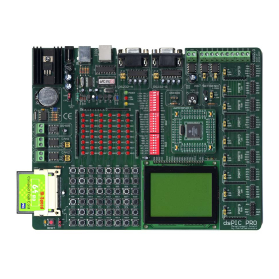
dsPICPRO
Advertisement
Table of Contents

Related Manuals for mikroElektronika dsPICPRO


Summary of Contents for mikroElektronika dsPICPRO
- Page 1 (ADC potentiometer, two RS-232, RS485, Compact Flash, CAN etc.), 2.0 programmer MikroElektronika development boards make fast and reliable tools that can satisfy the needs of experienced engineers and beginners alike. Software and Hardware...
- Page 2 INCIDENTAL, OR CONSEQUENTIAL DAMAGES(INCLUDING DAMAGES FOR LOSS OF PROFITS, LOSS OF BUSINESS, LOSS OF USE OR DATA, INTERRUP- TION OF BUSINESS AND THE LIKE) EVEN IF MIKROELEKTRONIKA HAS BEEN ADVISED OF THE POSSIBILITY OF SUCH DAMAGES ARISING FROM ANY DEFECT OR ERROR IN THIS MANUAL OR PRODUCT.
-
Page 3: Table Of Contents
MikroElektronika dsPICPRO User’s Manual Development tools CONTENTS CONNECTING THE SYSTEM page 4 INTRODUCTION page 5 DESCRIPTION OF THE DEVELOPMENT SYSTEM page 6 Switches and their functions page 6 Jumpers page 7 MCU card page 8 Power Supply and the Reset Circuit... -
Page 4: Connecting The System
Run and use dsPICFLASH2.exe as explained in the document ‘dsPICflash pro- grammer’. After these 5 steps, your dsPICPRO is installed and ready for use. You should try to read a program from the chip or to load an example from the examples folder. -
Page 5: Introduction
Development tools INTRODUCTION The dsPICPRO development system is a full-featured development board for Microchip dsPIC microcontrollers. It has been designed to allow students and engi- neers to easily exercise and explore the capabilities of dsPIC microcontrollers. It allows dsPIC microcontrollers to be interfaced with external circuits and a broad range of peripheral devices, allowing the user to concentrate on software develop- ment. - Page 6 Development tools SWITCHES The dsPICPRO development board features many peripherial devices. In order to enable these devices before programming, you need to check if appropriate jumpers or switches have been properly set. Switches are devices that have two positions - ON and OFF, which have a role to establish or break a connection between two contacts.
-
Page 7: Jumpers
MikroElektronika dsPICPRO User’s Manual Development tools JUMPERS Jumpers, like switches, can break or establish a connection between two points. Beneath the plastic cover of the jumper is a metal contact, which makes a connec- tion when the jumper is placed between two disconnected pins. -
Page 8: Mcu Card
MikroElektronika dsPICPRO User’s Manual Development tools MCU CARD The dsPICPRO development board have a 80-pin MCU Card as shown on the fol- lowing picture: Figure 4. MCU Card page M I K R O E L E K T R O N I K A S O F T W A R E A N D H A R D W A R E S O L U T I O N S F O R T H E E M B E D D E D W O R L D... - Page 9 MikroElektronika dsPICPRO User’s Manual Development tools When you are placing MCU Card on the dsPICPRO MCU socket you must follow these steps: Step no.1 If there is already MCU Card placed on dsPICPRO, you must remove it by slowly pulling it up.
- Page 10 MikroElektronika dsPICPRO User’s Manual Development tools The microcontroller’s pins are routed to various peripherials as illustrated in Fig.5. All ports have direct connections to Direct Port Access connectors. Such connectors are typically used for con- necting external peripherials to the board, or for providing useful points for connecting digital logic probes.
- Page 11 USB programming cable and jumper J1 should be set in the upper position. In case of an external power supply, the dsPICPRO board produces +5V using an LM7805 voltage regulator. The external power supply can be AC or DC, with a voltage between 9V and 16 V, and jumper J1 should be set in the lower position.
-
Page 12: On-Board Usb Programmer
ON-BOARD USB PROGRAMMER There is no need for the use of external equipment during programming, as the dsPICPRO development system has its own on-board USB programmer. All you need to do is connect the system to a PC using the USB cable. Then, load... - Page 13 LIGHT EMITTING DIODES Light Emitting Diodes (LEDs) are the most commonly used components, usually for displaying pin’s digital state. The dsPICPRO have 48 LEDs that are connected to the microcontroller’s ports RB low, RB high, RD low, RD high, RF and RG.
- Page 14 MikroElektronika dsPICPRO User’s Manual Development tools All LEDs from one port are connected to a common point through these resistors, which can then be connected or disconnected to ground by the corresponding switch on SW1. The LEDs are enabled when connected to a ground and will display the state of the corresponding microcontroller pin;...
-
Page 15: Push Buttons
MikroElektronika dsPICPRO User’s Manual Development tools PUSH BUTTONS The dsPICPRO has 48 push buttons, which can be used to provide digital inputs to the microcontroller's ports. There is also one push button that acts as a RESET (Figure 13). Figure 13. - Page 16 MikroElektronika dsPICPRO User’s Manual Development tools Which one of those two, depends on how J10 is set. It is illustrated on the next page. For the example shown in Fig. 15, pull-down resistors would be required. PORTG PORTF PORTB low...
- Page 17 MikroElektronika dsPICPRO User’s Manual Development tools In the case of Fig. 16 the pull-up resistor pulls the microcontroller port pin to +5V when the button is PortB Low pull-up not pressed. A button press causes the port pin to be connected to...
-
Page 18: Graphic Lcd
MikroElektronika dsPICPRO User’s Manual Development tools GRAPHIC LCD The Graphic LCD (GLCD) allows advanced visual messages to be displayed. While a character LCD can display only alphanumeric characters, a GLCD can be used to display messages in the form of drawings and bitmaps. The most common- ly used graphic LCD has a screen resolution of 128x64 pixels. - Page 19 MikroElektronika dsPICPRO User’s Manual Development tools In order to enable GLCD, jumper J23 should be set to the position labeled as GRAPH. LCD8 contrast selected GRAPH. Contrast Adjustment GLCD contrast GLCD and LCD8 selected contrast deselected CHAR. RG15 RC14 RC13...
-
Page 20: Lcd 2X16
MikroElektronika dsPICPRO User’s Manual Development tools LCD 2X16 When using a character LCD, it should be placed on the GLCD connector. Since GLCD connector has 20 pins and the character LCD has only 14 pins, special atten- tion is required when placing the LCD. Otherwise the LCD can be permanently damaged. - Page 21 MikroElektronika dsPICPRO User’s Manual Development tools In order to enable LCD, Figure 21. LCD 8-bit mode schematic jumper J23 should be set to the position labeled as CHAR. LCD8 contrast selected GRAPH. Contrast Adjustment GLCD contrast GLCD and LCD8 selected...
-
Page 22: Rs-232 Communication
Figure 23. RS232 connectors dsPICPRO development board have two RS-232 communication devices, RS232-A and RS232-B. In order to provide a more flexible system, the microcontroller is con- nected to the MAX232 through jumpers. First two jumpers J2 and J3 are used to connect Rx and Tx lines from microcontroller to RS232-A port, and second two jumpers J4 and J5 for connecting Rx and Tx lines to RS232-B. - Page 23 MikroElektronika dsPICPRO User’s Manual Development tools RS-232 Receive CONNECT data (Rx) MCU TO PC SERIAL CABLE CONNECT Send PC TO MCU Data (Tx) RS232-A SUB-D 9p RG15 RC14 RC13 RD11 RD10 RS232-A is RS232-A is disconnected connected 10uF RA15 MCLR...
- Page 24 MikroElektronika dsPICPRO User’s Manual Development tools RS-232 Receive CONNECT data (Rx) MCU TO PC SERIAL CABLE CONNECT Send PC TO MCU Data (Tx) RS232-B SUB-D 9p RG15 RC14 RC13 RD11 RD10 RS232-B is RS232-B is disconnected connected 10uF RA15 MCLR...
-
Page 25: Rs-485 Communication
RS-485 connector RS-485 connector dsPICPRO development board have one RS-485 communication device. In order to provide a more flexible system, the microcontroller is connected to the LTC485 through three switches on SW3. Switches 2, 3 and 4 are used to connect Rt, Tx and Rx lines from microcontroller to RS-485 port. - Page 26 MikroElektronika dsPICPRO User’s Manual Development tools Figure 28. RS-485 schematic and connection to other RS-485 modules RG15 RC14 RC13 RD11 RD10 B-485 RA15 MCLR RA14 dsPIC30FXXXX OSC2 A-485 OSC1/CLKI RA12 RA13 LTC485 2nd RS-485 MODULE 3rd RS-485 MODULE Figure 29.
-
Page 27: Can
CAN2 connector dsPICPRO development board have two CAN communication devices. In order to provide a more flexible system, the microcontroller is connected to the PCA82C250 through two jumpers for every CAN communication device. Jumpers J8 and J9 are used to connect Tx and Rx lines from microcontroller (pins RG1 and RG0) to CAN1. - Page 28 MikroElektronika dsPICPRO User’s Manual Development tools CAN1 CAN1 With two CAN com- Enabled Disabled munication devices Figure 32. CAN schematic you can create two separated networks. CAN1-H CANH CANL CAN1-L Vref PCA82C250 CAN2-H CANH CANL CAN2-L Vref PCA82C250 RG15 RC14...
-
Page 29: Ds1820 Digital Thermometer
-55C to 125C and an accuracy of +/-0.5C. It must be placed correctly in the 3-pin socket provided on the dsPICPRO, with its rounded side to the bottom, as marked on the board. Otherwise the DS1820 could be perma- nently damaged. -
Page 30: A-D Converter Input
A-D CONVERTER INPUT dsPICPRO development board have eight analogue signal inputs for working with ADC. One of that inputs, potentiometer P2, is active when switch 3 on SW2 is enabled and gives analogue signal to microcontroller’s RB10 pin. Potentiometer analogue output is in the range of 0V to 5V as drawn on the board. - Page 31 MikroElektronika dsPICPRO User’s Manual Development tools Both PGA integrated circuits (MCP6S22) are connected to microcontroller through SPI communication and have CS signal (Chip Select). In order to work properly, SPI communication must be enabled by setting switches 5 and 6 on SW3 in ON posi- tion (needs only SCK and MOSI because PGA only receives data from microcon- troller - data about amount of gain that will be applied to input signal).
- Page 32 MikroElektronika dsPICPRO User’s Manual Development tools Figure 38. A-D Converter input schematic AN8 and AN9 connected AN8 and AN9 connected directly to RB8 and RB9 through PGA1 and PGA2 PORTB high pull- up/down jumper CN10 CN11 CN12 CN13 should be romoved.
-
Page 33: D-A Converter Output
MikroElektronika dsPICPRO User’s Manual Development tools D-A CONVERTER OUTPUT DsPICPRO development board have DAC (Digital-to-Analogue Converter) that can sim- ulate analogue output from 0-5V or from 0- 4.096V depending of voltage reference. DAC- LD# and DAC-CS# pins must be connected... -
Page 34: Direct Port Access
MikroElektronika dsPICPRO User’s Manual Development tools DIRECT PORT ACCESS All microcontroller input/output pins can be accessed via connectors placed along the right-hand side of the board. For each of the ports PORTA, PORTB low, PORTB high, PORTC, PORTD low, PORTD high, PORTF, PORTG low and PORTG high there is one 10-pin connector providing Vdd, GND and up to eight port pins. - Page 35 MikroElektronika dsPICPRO User’s Manual Development tools Figure 42. Pull-up line is connected Lower Port D connection RN11 Pull-down line All lines is connected are disconnected CN21 RG15 RC14 RC13 RD11 RD10 RA15 MCLR RA14 dsPIC30FXXXX OSC2 OSC1/CLKI RA12 RA13 HEADER 5x2...
-
Page 36: Compact Flash
Compact Flash include digital cameras, digital music players, desktop computers, handheld PCs, personal communicators, Palm PCs, Auto PCs etc. so you can easily exchange data from them and dsPICPRO development board. Compact Flash have non-volatile storage solution that does not require a battery to retain data indefinite- Figure 43. - Page 37 MikroElektronika dsPICPRO User’s Manual Development tools Figure 44. Compact Flash schematic Compact Flash Card RG15 RC14 RC13 RD11 RD10 RG14 RA15 MCLR RA14 dsPIC30FXXXX OSC2 RG15 OSC1/CLKI RG13 RA12 RA13 CFCD RG15 page M I K R O E L E K T R O N I K A S O F T W A R E A N D H A R D W A R E S O L U T I O N S F O R T H E E M B E D D E D W O R L D...
-
Page 38: Real Time Clock (Rtc)
Such devices as clocks, timers, etc. are impossible to prod- uct without knowledge of exact time. Real Time Clock on dsPICPRO development board is PCF8583P, and it use I2C serial communica- tion to exchange informations with microcon- troller. - Page 39 MikroElektronika dsPICPRO User’s Manual Development tools If you are experiencing problems with any of our products or you just want additional information, please let us know. We are committed to meet every your need. Technical Support : support@mikroe.com If you have any other question, comment...
Need help?
Do you have a question about the dsPICPRO and is the answer not in the manual?
Questions and answers