Advertisement
Quick Links
Advertisement

Related Manuals for Alpha Technologies GSM-VarioBell


Summary of Contents for Alpha Technologies GSM-VarioBell
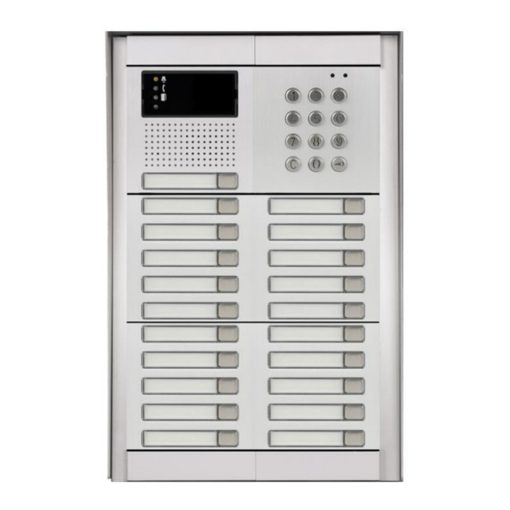
- Page 1 D O O R I N T E R C O M GSM-VarioBell User manual V 1.2...
- Page 2 Basic technical parameters: Power supply: 12 (9-24) V AC/DC, 500mA (optionally integrated ACU 2000mAh for approx. 35h of operation) GSM: 850/900/1800/1900 MHz modular system – via table dimension: buttons: 1 or 2 in basic solution. Possibility extend up to 87 buttons + keypad (for every button max.
- Page 3 • Voice signaling of different events (for example. „ wait please “, „Open “, etc. • SMS sending with date, time and numbers list from which was relay activated by ringing; date and time and code when relay is activated by keypad code. Function: Hands free GSM phone –...
- Page 4 a. From numbers saved in phone book on the SIM card only b. From any telephone number. 2. By code – • during voice communication (incoming as same as outgoing call) . The 1 digit code by DTMF might be dialed by called party for relay activation ( for preprogrammed time).
- Page 5 Bell generates into a call short beeps for time of input activation. Voice signaling of different status. Up settings might be different status signaling by voice. (language adjustable). When is voice signaling presented during a call it is hearable on both sides of connection (for example „open“) Detection of start/restart.
- Page 6 Button module VBDx-mod: VBD5-mod with 5 buttons VBD10-mod with 10 buttons Buttons order numbering is setup by DIP switch on each module (viz. follow). Keypad module VBDKey Keypad connection is not necessary to setup and it does not depend on the position where it is connected (see following pages).
- Page 7 Mechanical parts For easier explanation we show mechanical parts for 1, 2 and 3 modules. In one column are max 3 modules. The big set contents max 3 columns (9 modules). For even bigger sets you can put 9 modules set over or next each other. Mounting box for flush mounting: Mounting box-1 Mounting box-2...
- Page 8 Fixing and covering frame – for flush and surface mounting For 1 module for 2 modules for 3 modules design frame – flush mounting only Frame-1 Frame-2 Frame-3 Frame - 3 x 2...
- Page 9 roofing shield – flush mounting only Shield-1 Shield-2 Shield -2 x 2 SMB – surface mounting box – surface mounting only (fixing frames are extra) SMB-1 SMB-2 SMB-3...
- Page 10 control elements and connection SIM reader SIM reader Switch of backup Insert SIM for Insert SIM for battery. For operation operation operation to ON position restart button Expanding modules connector input Relay Relay...
- Page 11 Signalling Speaker loudness regulation speaker microphone BBUTTON ABUTTON...
- Page 12 Examples of relays connection Basic connection - 2 electrical locks and possibility control 2 doors 2x PSU – possibility to use 2x PSU independently. First for GSM-VB and second for electrical locks. Electrical lock number is connected reversely (emergency exit). Activation of external camera or light.
- Page 13 Connection of extending modules VBD10(5)-mod Buttons extending modules are VBD10-mod with 10 buttons and VBD5-mod with 5 buttons. Buttons numbering will be explain further but it is done on each button module by DIP switch (6). PCB board with components VBDx-mod is connected to button module by screw terminal only (5) and via 3 wire cable (4).
- Page 14 Connection K2 cable to VBG-xx module K2 cable (cable with red connector) ATTENTION! Key of the connector (protrusion) toward the bottom edge connector. K2 connection to VBDx module...
- Page 15 Example of connection VBD10-mod and VBDKey Connection of each extending modules is done by flat cable K1. Nearest extending module to basic module is connected by cable K2. Modules´ numbering is setup by DIP switches (6) of each module. It not depends on connection order of each module but on DIP switch setting.
- Page 16 Buttons numbering Expansion modules buttons´ numbering depends on the DIP switch setting only. The button´s name is always described by alphabetic B (button), button number (via button numbering) and after the dash by order marking of the phone number assigned to the button. For example: B1-1 is a mark of the phone number for the button 1 which will be dialed as the first one in order (immediately after pressing the button)
- Page 18 Module’s numbering is on picture. In left part are modules with 5 buttons VBD5-mod and in right part are modules with 10 buttons VBD10-mod. The module with the desired number can be found on this picture and next on the left side there is a combination of the DIP switch (6), which you have to setup on the button´s module!
- Page 19 Keypad VBDKey connection Keypad module is connected by the same flat cable as button modules VBD10(5)-mod Cancel of pressed character (Back Space) Symbol to insert the password (code) Dial or memory number is performed by progressive pressing of number buttons. To insert password for door opening you have to press first button with key symbol cancel just inserted number press (Back Space).
- Page 20 Basic module signaling on the front panel mechanical front panel allows in basic module window LED signaling of door phone status. This signaling follow requirement of handicap law. Bell symbol (red) – ringing during reaching call party Handset symbol (blue) – call picked up (speech) Open door symbol (green) –...
- Page 21 Installation...
- Page 22 Mounting process: A. Preparation of mounting holes in the wall – recommended height is about 160cm from ground. Dimension of holes depends on number of modules and here we mention dimensions for 1,2 and 3 modules (basic mounting boxes). The bigger sets are completed from those boxes by their combination (under or next each other).
- Page 24 Start operation 1. connect antenna and insert the SIM we recommend use SIM without PIN. When is not possible setup PIN1234. by shift you release SIM holder from lock (1). lift up the holder (2). Insert the SIM in correct direction (3) into holder.
- Page 25 setup GSM-VB after switching ON via bellow described procedures. When you want to use call reject (ringing) then ask GSM operator to deactivate your voice mail on used SIM card! SIM card pre-programming 1. The SIM card, which you will use in the GSM-VB, needs to be prepared.
- Page 26 2. Switch ON GSM-VB Switch on the unit only after you have connected all required wires (relays, locks, etc.) Be careful when connection the antenna. Only at the end connect the power supply adapter. The red LED will light up and after a few seconds, the yellow LED will start flashing (see table LED signaling on page 61).
- Page 27 Due security reasons, the parameters of the GSM-VB are possible to setup from numbers saved on the SIM card under names ADMIN1 to ADMIN9 only. SMS are always written in CAPITAL (BIG) LETTERS! Each SMS elements are always split by space (words). First word is always command.
- Page 28 setting. Initially by the SMS „READ PAR“ read the current setting to your mobile phone. 6. By editor of SMS messages change at received SMS word READ to WRITE as well as adjust parameters based on your needs. Such adjusted SMS send back to GSM-VB as a reply.
- Page 29 Mode monitor To setup parameters stop program running in GSM- Do not press to operation monitor! You stop GSM- VB operation! Indication of serial line operation After connection establishment with GSM- VB will show indication of After connection establishment voltage in GSM-VB with GSM-VB will show indication of GSM signal strength...
- Page 30 After click to monitor button is possible monitor operation in GSM-VB (when operation is not stopped by button STOP) Report saving from monitor to file (for support purposes – report sending) Mode programming After button STOP pressing program sends to GSM-VB command to STOP and wait for GSM-VB feedback (via picture) Waiting for GSM-VB...
- Page 31 folder Buttons It is design to program phone numbers under each button and for cooperation with keypad (insert phone numbers to memory and insert codes) One button folder Field to program up to 7 phone numbers for one button Field to program up to 7 phone numbers for right button Folder for two buttons...
- Page 33 Folder for expanding button modules List of all memories and phone numbers of each buttons saved on SIM card. List is arranged according buttons. List of all memories and phone numbers for button selected from list on the right (by click on various memory of this button) ON/OFF function „Buttons Detect”.
- Page 34 Edit of selected number (insert number instead of „P“) Select button to edit List of edit with all appropriates phone numbers saved on SIM for this button (here just one record – P) After click to selected memory (here just one – B2-1) will occur in edit fields each elements of record (via description of previous page) Order in dialling...
- Page 35 Adding of button (function for automatic button detect wasn’t used) Process similar like in previous example (click on „Add Button“). BUT is necessary: i. setup required button number ii. setup required order of phone number in dialling Those parameters in previous example (adding number to order for preselected button) have been created automatically.
- Page 36 Folder for keypad module Folder to work with memories Direct dialling of phone number from keypad. Dialed number is firstly searched between memories of phone numbers. When don’t find the number then dial number to GSM network Waiting time for next number dial. When you exceed the time the previous dialed numbers are sent to unit (memory number or direct phone number) Work with phone numbers memories saved under selected...
- Page 37 Folder for keypad module Folder for work with codes (passwords) for relay activation (opening) Correction system, erasing and inserting new passwords is similar as in previous. Work with codes will be described in follow text. Adding code Erasing selected code List of codes saved on SIM Position on SIM 33:C444C[2#4#10#14#**#0]...
- Page 38 Work with codes (passwords) 5 modes of codes (M0-M4) After code selection from list will be automatically setup appropriate folder. When you insert a new password, you have to select appropriate folder ( according required code features) manually. Name under which is password saved on SIM Every folder has: Field to insert number of code...
- Page 39 The simplest mode – selected relay will close after inserted code from keypad for preprogrammed time. (via parameter time of relay activation further in manual) After code insert the relay close in preprogrammed days of week only. The GSM-VB might also calculate number of used codes and when number exceed preprogrammed value (for example number of prepaid entrances) the code is refused.
- Page 40 After inserting the code relay is activated in range of setup dates (included). Code using might be announced by sending SMS with date, time and used codes Setting of month and day from which is access permitted Setting of month and day until which is access permitted After code insert the relay is activated from setup date.
- Page 41 After inserting the code relay is activated in range of setup hours (working time). The GSM-VB might also calculate number used codes when number exceed preprogrammed value (for example number of prepaid entrances) the code is refused. Code using might be announced by sending SMS with date, time and used codes.
- Page 42 Folder Phone Book Phone book of authorized numbers to activate relay by ringing and automatic calls receiving. Position for name Position for phone number Add row on top of row with cursor Erase row with cursor Find inserted name...
- Page 43 Folder Setting – parameters setting Folder Calls csacallshovo Setting loudness of speaker Setting loudnes of microphone Way of calls receiving: - do not receive (open by ringing) - automatically pick up calls from numbers from list only - pick up all calls Signaling - inform tones of GSM-VB - incoming call ringing...
- Page 44 Folder relay Setting parametres for relay 1 Setting parametres for relay 2 Relay modes: - camera - light - button - control by SMS - control by code or ringing Relay control by ringing from numbers saved on SIM only Relay control by ringing from any number DTMF code to activate relay...
- Page 45 Folder SMS Number where is sent SMS „ALARM ON” when input is activated Number where is sent SMS „ALARM OFF” when input is deactivated Input mode: - Input deactivated - Tones when input is activated during a call (opening signaling) - SMS sending SMS sending to ADMIN1 with list of numbers from which was...
- Page 46 Folder ADMIN numbers setting Field to save up to 7 ADMIN numbers When all necessary is setup then save all by button „Save“ to GSM-VB. (when you did setup buttons ,passwords or memories in extending modules – they are saved automatically when you press button „Write…“.
- Page 47 Folder Service It is intended for upgrade fw and voice information in GSM-VB. ATTENTION! Improper use can cause the GSM-VB to block. List of files to be uploaded to GSM-VB (can be edited manually) Loading the list from the PC Clearing the list Start writing files from the list to GSM- VB.
- Page 48 Press the "Run" key to restart GSM-VB - return from programming mode to monitor (stand by) mode (restart of GSM-VB) For return to monitor mode (start of GSM-VB) click on button „Run“. Program detects start of GSM-VB the same way as stop: GSM-VB behaves after restart the same way as during power supply connection (tones, eventually voice info).
- Page 49 Table of commands for SMS Command ( SMS) Function Def. READ STAT GSM-VB status reading (version, 4as, status, rel0 etc.) READ PAR Reading of all set parameters READ NAME Reading of phone number for NAME CLR NAME Erase of phone number for NAME INIT ADMIN1 +420cc…c First setting of GSM-VB –...
- Page 50 0 – OFF 1 - ON WRITE PAR TMGSM:x Setup time according GSM network x: 0 – OFF 1 - ON WRITE PAR TONE:x Setting of sound signaling x: 0 - OFF 1 – ON with service tones 2 – ON ringing of incoming call 4 –...
- Page 51 x=4 – close for „activation time“ after button press x=5 – extra switch mode (by ringing from any number or by code) WRITE PAR RL1TMON:yy Activation time for relay 1 after ringing or by code activation yy seconds yy=00-99 WRITE PAR RL1RING:x Relay 1 activation by ringing x=0 –...
- Page 52 y sec y= 1-9 WRITE PAR DDIAL:x permit/ prohibit direct dialling from keypad: x=0 – prohibit x=1 – permitted Write number for SMS „ALARM ON“ WRITE ALARMON +420cc..c (input grounding) Write number for SMS „ALARM WRITE ALARMOFF OFF“ +420cc..c (input disconnect) CAL AT+CSQ GSM signal strength level CAL AT+CPBR=x...
- Page 53 Types of commands: READ – command to read parameters and phone numbers from the SIM card. It means also reading of phone numbers saved under buttons (for example READ B1- 1), in memories (for example READ M1234-1), codes setting (for example READ C123C) or parameters of GSM-VB in internal format (READ PARGDI) CLR - command to erase phone numbers from the SIM card.
- Page 54 Meaning of names saved in phone book name function ABUTTON1 - this number is called by GSM-VB when button is pressed (right) - by ringing activate relay 1 and relay 2 - from this number are automatically received the calls ABUTTON2 - this number is called by GSM-VB when number under button ABUTTON1 is not reachable, busy or not pick up the calls...
- Page 55 ABUTTON6 is not reachable, busy or not pick up the calls - by ringing activate relay 1 and relay 2 - from this number are automatically received the calls BBUTTON1 this number is called by GSM-VB when button on the left is pressed (version with 2 buttons) - by ringing activate relay 1 and relay 2 - from this number are automatically received the calls...
- Page 56 - by ringing activate relay 1 and relay 2 - from this number are automatically received the calls - by ringing activate relay 1 and relay 2 ADMIN2 - By SMS activate relay 1 and relay 2 - By SMS read status and numbers in phone book ADMIN7 - By SMS edit numbers and names on SIM card - By SMS control other features (AT commands)
- Page 57 A#1#CDEFGHI#JJ#K A –– relay from which is code dialed [1,2] C – Monday: 1 permitted, 0 prohibited D - Tuesday: 1 permitted, 0 prohibited E - Wednesday: 1 permitted, 0 prohibited F - Thursday: 1 permitted, 0 prohibited G - Friday: 1 permitted, 0 prohibited H - Saturday: 1 permitted, 0 prohibited I - Sunday: 1 permitted, 0 prohibited JJ –...
- Page 58 When name will be saved in format CODECXXXXC, when CXXXXC is code saved on SIM (via in table above), will be the same rules of code for this number for activating by ringing like is written in code - it is send to this number SMS „ALARM ON“ when input is closed ALARMON against ground - it is send to this number SMS „ALARM OFF“...
- Page 59 for „closing time“ after hang up 4 – button mode, close for „closing time“ after button press 5 – extra switch mode, close by ringing from any number or by DTMF code during call CC – closing time [00-99] D – closing of relay by ringing: 0 – off 1 –...
- Page 60 ALARMOFF, PARGDI, PARRL1, PARRL2, button names (B…), memory names (M…), code names (C….C) must be written in CAPITAL (BIG) LETTERS. Between the letters there is not any space! Answer of GSM-VB to SMS „READ STAT“ READ STATUS: VER: 101 BATTERY:4030mV TIME: "00/01/01,00:01:55"...
- Page 61 Tones GSM-VB Except ordinary tones and signaling of GSM communication (ringing tone, busy tone, different operator messages), has GSM-VB own signaling (via setup possibilities). High tone- notification Middle high tone – control action ...
- Page 62 LED signaling Do not light Flashing space and light the same length Yellow LED PCB Short flashing in 2 sec. period ▌ ▌ ▌ Permanent light Do not light ...
- Page 63 GSM-VB with a backup battery When you have GSM-VB with backup battery (included) after unit connection just turn a switch of backup battery to position „ON“ (see the picture) Do not store your GSM-VB with an inserted backup battery and switch in position „ON“! You might damage the battery! The unit will be out of warranty.
- Page 64 CAUTION! After the battery is inserted, the red LED MUST NOT light up. This indicates there is a wrong polarity. In this case take out the battery immediatelly! After getting GSM-VB to operation by turn switch to position ON you connect backup battery We do not take any responsibility for the doorphone´s damaging if you do not follow the...
- Page 65 Technical parameters: Dimension according used modules Operating position various temperature: -20 to + 50°C Operating condition humidity: 10% ÷ 80% when 30° C power voltage 12 (9-24) V AC/DC, min. 500mA (optional backup battery Li-18650 min 2000mAh for approx. 35h of operation) buttons 1 to 87 according used modules...
Need help?
Do you have a question about the GSM-VarioBell and is the answer not in the manual?
Questions and answers