Table of Contents
Advertisement
Quick Links
Advertisement
Table of Contents

Related Manuals for Lithium Grim Oceanic Delay


Summary of Contents for Lithium Grim Oceanic Delay
- Page 1 Oceanic Delay Building instructions V1.1...
-
Page 2: Table Of Contents
Table of contents Components ............................3 General guideline for components......................4 General building tips ..........................4 Modifications ............................5 Tap Tempo Daughterboard ........................5 Offboard wiring ............................6 Troubleshooting ............................8 Schematic ..............................9... -
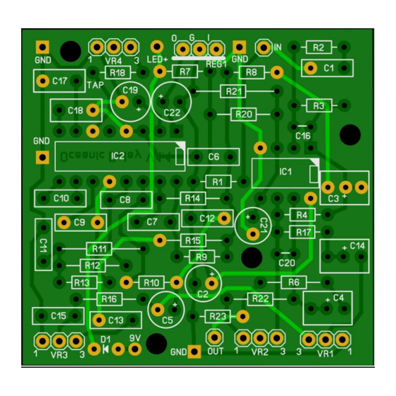
Page 3: Components
Components Part Value Comment Part Value Comment Part Value Comment C18 100n 100u Electrolyte C19 47u Electrolyte R12 Electrolyte C20 100p Ceramic Electrolyte C21 47u Electrolyte R14 Electrolyte C22 47u Electrolyte R15 1N5817 TL072 Socket PT2399 Socket 100n MKT C10 100n MKT 180k C11 15n 360k... -
Page 4: General Guideline For Components
General guideline for components Capacitors: All values under 1nF should be ceramic disks. From 1nF up to 1uF should be MKT (foil/metal film capacitors) and over 1uF use electrolyte caps (or tantalum) 16V+ rated and watch out for polarity! In this build there are some deviations from this rule so we marked all capacitors with the required type in the table on page 3. -
Page 5: Modifications
Modifications If you want darker repeats then you can replace the C11 (15nF) with a higher value or make it switchable like this (middle position is stock value of 15nF). You are free to choose different values! Some people prefer another IC than the TL072. You could try a OPA2134 instead. Tap Tempo Daughterboard If you are planning on using a taptation tap tempo daughterboard (sold separately, contact your seller) then do not connect R18 and VR4. -
Page 6: Offboard Wiring
Offboard wiring Anode (long leg) Cathode (short leg) R led Ring Sleeve Ring Output Jack Input Jack Blue = pin 1 White = pin 2 Yellow = pin 3 Notice that in the “off” position the effect input is connected to ground to prevent possible oscillation. - Page 7 If you decide to use the tap tempo daughterboard in a separate case you can wire it like this: Ring Output to Taptempo board Anode (long leg) Cathode (short leg) R led Ring Sleeve Ring Output Jack Input Jack Footswitch Blue = pin 1 White = pin 2...
-
Page 8: Troubleshooting
Troubleshooting All PCB’s have been e-tested 100% in the factory, so there should not be a connection problem on the PCB itself. The board is not working (at all), what now? Check if your 9V is plugged in correctly (and/or soldered correctly on the board). ... -
Page 9: Schematic
Schematic...
Need help?
Do you have a question about the Oceanic Delay and is the answer not in the manual?
Questions and answers