Advertisement
Quick Links
Advertisement

Related Manuals for AURATON T-1 RT


Summary of Contents for AURATON T-1 RT
- Page 1 T-1 RT O W N E R ’ S M A N U A L w ww . au raton . pl...
- Page 2 Operation under the load of up to 16A/10A The AURATON RT receiver is equipped with a relay capable of operating with the load of up to 16A/10A. Its low-sparking technique of switching mains voltage contributes to the low wear of relay contacts.
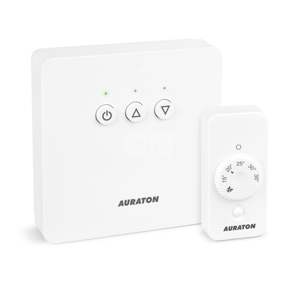
- Page 3 – setpoint bottom indicating of antifreeze pairing with temperature (7°C) a receiver temperature sensor Front Back AURATON T-1 is equipped with pre-installed lithium battery. Life span of the battery is up to 20 years. ATTENTION: unchangeable battery.
- Page 4 Description of the AURATON RT receiver The AURATON RT receiver works with the wireless AURATON T-1 controller. The received is installed near the heating or air conditioning device and may work with the load of 16A/10A. diode indicating that diode indicating that...
- Page 5 If devices with higher power are connected, the cables should be replaced with ones of appropriate cross-sections. NOTE: When installing an AURATON RT receiver, make sure that the power supply is switched off. The receiver should be installed by a professional.
- Page 6 (5 mm). 4. Put the wall plugs in the drilled holes. 5. Fasten the AURATON RT receiver to the wall using screws so that the receiver is well fastened. NOTE: If the wall is wooden, there is no need to use wall plugs. In such a case, drill two holes 2.7 mm in diameter instead of 5 mm, and screw the screws directly into the wood.
- Page 7 1. Drill two 5 mm holes in the wall (select the span of holes with a wall-mounted holder-enclosed to the set with con- troller AURATON T-1 2. Insert the wall anchors to the holes (attached to a set). 3. Fix the mounting plate to the wall.
- Page 8 ) a single sound signal is emitted – on the AURATON RT receiver and by holding it pressed for at least 3 s until the LED diode starts blinking with green light (double sound signal) – then the button must be released.
- Page 9 2 seconds. When LED diode ( ) will starts flashing red stop pressing the button. 3. A properly completed deregis-tering process is signalled by the LED on the AURATON RT receiver no longer flashing red and the receiver reverting back to normal operation.
- Page 10 AURATON RT AURATON T-1 AURATON T-2 AURATON H-1 Receiver connected Wireless Wireless thermometer Window handle to the heating device temperature (sold separately) (sold separately) controller A simplified schematic of connecting the AURATON RT receiver with the heating device heating device...
- Page 11 - in that room, you install the T-2 thermometer, and the AURATON T-1 regulator in e.g. the kitchen. This way the temperature in the “children’s room” will always be at 22°C regardless of temperature fluctuations in the kitchen.
- Page 12 When you open a window equipped with the H-1 handle paired for longer than 30 seconds, the relay in the AURATON RT receiver is switched off, as is the connected heating device. If all the assigned windows are again in a state other than “opened”, the RT receiver returns to normal cooperation with the AURATON T-1 regulator and/or the T-2 thermometer no earlier than 90 seconds after switching off the relay.
-
Page 13: Special Situations
24 hours of operation until the problem is removed. • When both signals return (from the AURATON R25 RT regulator and the T-2 thermom- eter), the error is cancelled and the receiver enters its normal mode of operation. - Page 14 The AURATON RT receiver connection schematics CONTROL HEATING ~230V AC DEVICE e.g. a gas furnace ELECTRIC HEATING DEVICE MAX ~230V 16A PROTECTIVE...
-
Page 15: Technical Specifications
Additional information and notes • The AURATON T-1 regulator and/or the T-2 thermometer must be installed at least 1 metre from the RT receiver (too strong a signal from thetransmitters can cause interference). • At least 30 seconds must elapse between switching the relay off and on. - Page 16 20190408...
Need help?
Do you have a question about the T-1 RT and is the answer not in the manual?
Questions and answers