Table of Contents
Advertisement
Quick Links
Advertisement
Table of Contents

Related Manuals for AURATON S03 RTH


Summary of Contents for AURATON S03 RTH
- Page 1 S03 RTH ALARM RESET U SE R ’S MANU AL...
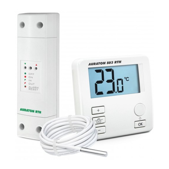
- Page 2 Wireless central heating pump controller AURATON S03 RTH The AURATON S03 RTH controller is tended for wireless control of a central heating (CH) pump. Before you start using the controller, please read this instruction carefully.
- Page 3 APPLICATION AURATON S03 RTH is intended for automatically switching on and off circulation pumps depending on the temperature. The controller- pump assembly forces the water to circulate in the central heating system with a coal-fired boiler or a gas boiler. The controller's sensor measures the temperature of the water on the supply side of the CH system.
-
Page 4: Description Of The Controller
Description of the controller On the front part of the enclosure there is a backlit LCD display and four function buttons. LCD display a temperature increase button a confirmation or controller on/off button a button for the reduction a temperature of the programmed decrease button pump shutdown temperature mode... - Page 5 Display 1. Temperature In the normal operation mode, the controller displays the temperature in the room where it is installed. 2. Discharged battery ( ) The indicator is displayed when the permissible minimum battery voltage level is exceeded. The battery must then be replaced as soon as possible.
- Page 6 3. AntyStop mode activation indicator This mode prevents seizing of the rotor of an unused pump. 4. Temperature unit ( This indicates that the temperature is displayed in degrees Celsius. 5. Activated pump indicator ( A pictogram that indicates the operating status of the pump. It is displayed when the controlled device is switched on.
- Page 7 Description of the RTH receiver The RTH receiver works with the wireless AURATON S03 controller. It can work at the load equal to 16 A. The receiver is installed at the CH pump. hole for the screw fixing the receiver to the wall...
- Page 8 Key - description of diode signaling in the receiver The diode is illuminated green - the operating device is off (the COM and NC contacts are closed). The diode is illuminated red - the operating device is on (the COM and NO contacts are closed). The diode is blinking green - the receiver is waiting for the device to be paired - (chapter “Paring of a wireless controller with the receiver”).
-
Page 9: Installation/Replacement Of Batteries
Installation/replacement of batteries The battery compartment can be found inside the controller, on the front part of the enclosure. In order to install the batteries, take off the enclosure. battery compartment - 2 x AAA 1,5 V batt. Put two 1.5 V AAA batteries inside the battery compartment, paying attention to the polarity of the batteries. -
Page 10: External Temperature Sensor
External temperature sensor External Terminal temperature sensor block As a standard, after the battery is put in, the controller without a sensor connected displays the temperature from the internal temperature sensor. When the external temperature sensor is connected, the controller automatically reads the values measured by that sensor. - Page 11 Fastening the RTH receiver NOTE ! When installing the receiver its power supply must be disconnected. It is recommended that the installation is performed by a qualified specialist. The permanent electrical system of a building must include a breaker and an overcurrent protection.
- Page 12 5. After connecting the conductors, they must be secured with the cable tie clamps and reinstall protective covers of the receiver. WARNING ! Cables supplied with the regulator are designed for conducting maximal load of 2.5 A. If devices to be connected require more power, the cables need to be replaced with cables of the appropriate cross-sectional area.
- Page 13 hole for fastening the receiver to the wall with a screw ALARM RESET hole for fastening the receiver to the wall with a screw NOTE: If the wall is wooden, there is no need to use wall plugs. In such a case, drill two holes 2.7 mm in diameter instead of 5 mm, and screw the screws directly into the wood.
- Page 14 - ) on the receiver and holding it for at least 2 seconds, until the LED starts flashing green, and then releasing the button. The AURATON RTH receiver waits for pairing for 120 seconds. After that time, it automatically returns back to normal operation.
- Page 15 - ) on the receiver and holding it for at least 2 seconds, until the LED starts flashing red, and then releasing the button. The AURATON RTH receiver waits for deregistering for 120 seconds. After that time, it automatically returns back to normal operation.
- Page 16 Signalling operation and reception of data packet Each radio transmission received by the AURATON RTH receiver from the paired device is signalled by a temporary change of LED colour to orange. Switching on the relay is signalled by the LED lit red, whereas switching it off is...
-
Page 17: Temperature Setting
Switching the controller on for the first time After the batteries are properly installed in the battery compartment, the LCD display shows all segments for one second (a display test) and then it shows the software version. After a moment, the current temperature in the room is displayed. - Page 18 2. Use the [plus] [minus] buttons to set the desired temperature in the room with the accuracy of 1°C. 3. Confirm the selection by briefly pressing the [OK] button. Setting the “reduction of the programmed pump shutdown temperature” The controller has the functionality of reduction of the pump shutdown temperature.
- Page 19 Switching the “AntyStop” mode on/off In order to switch the AntyStop mode on, press and hold the [clock] button pressed for 3 seconds. The display shows [AS] (the function is active). The AntyStop mode prevents seizing of the rotor of an unused pump. Also, a built in processor starts the pump every 14 days for 30 seconds after the heating season is over.
-
Page 20: Additional Functions
Additional functions After batteries are installed, the controller displays the ź temperature from the external temperature sensor. When the external sensor is connected (the terminal block is ź located under the enclosure), the controller automatically takes the readings from that sensor. If the external sensor is disconnected or defective, the ź... - Page 21 Wiring diagram showing the connection of the CH pump to the RTH receiver controller max. approx. 230 V pump temperature sensor central heating approx. 230 V AC boiler RTH receiver...
-
Page 22: Technical Data
Technical data Operating temperature range: 0 – 45°C Temperature measurement range: 0 – 99°C (HI is shown when out of range) Temperature control range: 0 – 85°C Default temperature setting: 30°C Additional function: AntyStop Operation status control: LCD display / LED diodes Maximum load current on the relay: approx. - Page 24 20180223...
Need help?
Do you have a question about the S03 RTH and is the answer not in the manual?
Questions and answers