Ditel KOSMOS Series Instruction Manual
Multi-function integrator, multi-input indicator, load-cell, process potentiometer
Hide thumbs
Also See for KOSMOS Series:
- Instruction manual (54 pages) ,
- Manual (51 pages) ,
- User manual (31 pages)

Subscribe to Our Youtube Channel
Related Manuals for Ditel KOSMOS Series


Summary of Contents for Ditel KOSMOS Series
- Page 1 MULTI-FUNCTION INTEGRATOR MULTI-INPUT INDICATOR LOAD-CELL, PROCESS POTENTIOMETER MODEL KAPPA-M PROTOCOL MODBUS-RTU COMPATIBLE INSTRUCTION MANUAL Valid from s/n: 188958 Code: 30727152 Edition: 15-03-2004...
- Page 2 Introduction to the kosmos series Custom CONFIGURATION for specific applications can The KOSMOS SERIES brings a new philosophy in be made quickly and easily through five front panel digital panel instrumentation, which is expressed by keys, following structured choice menus aided by multipurpose, modular-concept devices providing a display prompts at each programming step.
- Page 3 INDEX General information Page 1.1. Introduction 1.2. Panel functions description Setting up 2.1. Package contents 2.2. Supply. Connectors 9-10 2.3. Input configuration. Connections 11-12-13 2.4. Programming introduction 15-16 2.5. Input configuration diagram 2.6. Display configuration diagram 18-19 3. INPUT 3.1. Input configuration. Math functions 4.
- Page 4 RS232C/ RS485 ANALOG OUTPUT OUTPUT OPTION OPTION RELAYS/ OPTOS OUTPUT OPTION INPUT CARD CASE WITH POWER CIRCUIT FIXING CLIPS FILTER FRONT COVER DISPLAY MAIN BOARD...
-
Page 5: General Information
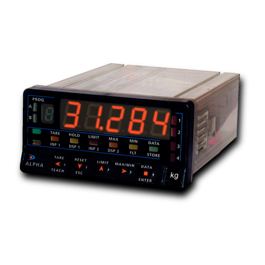
1. GENERAL INFORMATION 1.1. Introduction to KAPPA -M KAPPA-M instrument designed for measuring and Main performances: integrating analog signals having two information at the Accepts input signals like: same time, like FLOW and TOTALIZER. Accepts in addition Load Cell, Pressure transducers, Flow meters (measuring of two simultaneous analog input signals allowing arithmetical instantaneous FLOW as well as TOTAL accumulated), operation between them. - Page 6 1.2. Description of panel functions in mode (RUN) MAIN DISPLAY Shows the value of selected channel LED HOLD LED’s of setpoint Shows that display is frozen Show which relay is activated HOL D LED TARA Shows that variable on main TARE display has a tare value in the memory...
-
Page 7: Main Display
1.2. Description of functions panel in mode (PRO) MAIN DISPLAY Shows the variable to be programmed or the parameter to be selected HOL D TARE AUXILIARY DISPLAY TARE RESET LIMIT VISUAL DATA AUXILIARY DIGITS Shows the programming step Show the program menu ENTER number ESC KEY... -
Page 8: Getting Started
2. GETTING STARTED 2.1. Package Contents PACKAGE CONTENTS Programming instructions (Pages 15) The software is divided into several independently Instructions manual in English including Declaration of accessible modules for configuration the input, Conformity. the display, the setpoints, the analog output, the D.P.M. -
Page 9: Power Supply
2.2. Power supply Should any hardware modification be performed, remove Table 9.1: Jumpers situation the electronics from the case as shown in figure 9.1. 230V AC 115V AC 48V AC 24V AC fig. 9.1 : Disassembly 115/230 V AC: The instruments with 115/230 V AC power, are shipped from the factory for 230 V AC (USA market 115 V AC), see figure 9.2. -
Page 10: Installation
POWER CONNECTION - CN1 INSTALLATION To meet the requirements of the directive EN61010-1, where the unit is permanently connected to the mains supply it is obligatory to install a circuit breaking device easy reachable to the operator and clearly marked as the disconnect device. - Page 11 Transmitter connection 0-10 V or 0-5 V Input type connection See connections advices on Pág.10 External power supply PIN 6 = -EXC[Output excitation (-)] PIN 5 = +EXC[Output excitation (+)] CN 3 4 wires connection PIN 4 = +IN[Input mA (+)] (INP1) - EXC external TRANSDUCER...
- Page 12 Process input mA with external supply Potentiometer connection with Input Impedance > 10 MΩ CN 3 4 wires connection - EXC external TRANSDUCERR suuply + EXC 0 - 20 mA - IN (mA) POT. 4 - 20 mA - OUT +IN (mA) + OUT 3 wires connection...
- Page 13 Excitation from KAPPA -M CN 3 4 wires connection - EXC TRANSDUCER + EXC 0-20 mA Connection with two Transmitters 4-20 mA - IN (mA) - OUT 4-20 mA + IN (mA) + OUT CN 3 2 wires connection TRANSDUCER + EXC CN 3 3 wires connection...
- Page 14 This page has been intentionally left blank...
-
Page 15: Programming Instructions
2.4. Programming instructions How to get into programming mode? First, plug the instrument to the corresponding supply, automatically, a display test will be done and after that the software version will be shown, then the instrument will go to work. Second, press the key to enter into programming mode, on auxiliary display the indication ENTER "-Pro-"... - Page 16 Accessing to programmed parameters Programming numerical values Thanks to the tree structure, the programming routines When the parameter is a numerical value, the display will allows to access to change one parameter without passing show the first digit to be programmed blinking (on main through the whole list of parameters.
- Page 17 2.5 Input type configuration diagram. C n F I n I n P - I n P - M A t Y E S A d d S u b S M u L t d I V I n P - I n P - M A t M A t...
- Page 18 2.6 Display configuration diagram. C n F d S P S C A L t E A C H I n t E G I n P - 1 I n P - 2 I n P - 1 I n P - 2 t b A S E t b A S E t b A S E...
- Page 19 F I L t d I S P F I L t - P r o u n d r o u n d r o u n d r o u n d Y E S F I L t - E L F t - 0 L F t - 0 - P r o -...
-
Page 20: Input Configuration
3. INPUT 3.1 – Input configuration After the connection test is possible to get the input configuration (The instrument should be without locking the programming access) Press to get 11 InP-1, which allows programming the input type for channel 1, pressing get 12 InP-2 and other ENTER press of... -
Page 21: Display Configuration
4. DISPLAY CONFIGURATION 4.1 CONFIGURATION by SCAL or TEACH After to have on display 20 CndSP following indications on Page 15 pressing ENTER access to the display programming where we can scale the display range, be by key board or by TEACH mode with actual input signal values, it’s also possible to program the Integrator, Filters, Round of last digit as well as level of bright of display. - Page 22 4.2 LINEALIZATION by SEGMENTS If after programming display 2 of selected input, holding the Types of relationships ENTER key more than 3 seconds, accede to the programming of In the figure down are represented graphically the two ways more segments up to 15, which allow to linearize practically any of defining display range.
- Page 23 4.3 SQUARE ROOT CONFIGURATION The display configuration in square root application can be done or applying the next formula, display =offset + coef. * √ input if the offset and coefficient are known or programming as in a lineal way introducing the input value and display value corresponding to that square function for the two points of this line.
- Page 24 4.4 FILTERS BALANCED FILTER In this menu can configure the balanced filter to avoid not desired display fluctuations when the input signal is not stable. Allows choosing the level of filter between 0 and 9. The result of greater value of filter is a smooth answer on display to changes of input signal.
-
Page 25: Left Zeros
LEFT ZEROS In this menu can select the possibility to activate or not the left zeros on display, being this selection common for both displays (instantaneous and Total) BRIGHT LEVEL In this menu can select the level of bright for both displays. Allowing choosing between Hi and Lo. - Page 26 5. INTEGRATOR INTEGRADOR configuration. After getting level 20 pressing ENTER access to the level where pressing allows to arrive to 23 IntEG where all INTEGRATOR parameter are configured (see diagram) Selection (pressing several times the key) the Base-Time • s, M, H, d of integration according to the used transducer (Ex. Litres / minute, gallons / hour etc.
- Page 27 6. KEYBOARD AND CONNECTOR FUNCTIONS. LOCKOUT Index SECTION Page. 6.1. Keyboard functions 6.2. Programmable logical functions on rear connector en connector 6.2.1. Wiring 6.2.2. Functions table 28-29 6.2.3. Functions programming 6.3. Lockout programming and keyboard functions 33-34...
-
Page 28: Keyboard Functions
6.1. Keyboard functions TARE key LIMIT key Takes the current reading on display as TARE value Shows cyclically, on every press, the setpoint values. and makes the display read 0 for this input. If the setpoint is related to a PROCESS variable its value is Only the input 1 and input 2 variables can use shown on main display since on auxiliary display show the TARE function. - Page 29 6.2 – PROGRAMMABLE LOGICAL FUNCTIONS The rear connector CN2 pro vides 4 user programmable optocoupled inputs NPN or PNP that can be operated from external contacts or logic levels supplied by an electronic system. Four different functions may be then added to the functions available from the front -panel keys.
- Page 30 6.2.2. Functions table Definition of ACTION Pulse: The function is active on falling down edge at the corresponding pin respect to common Level: The function will be active as long as the corresponding pin remains at low lever respect to common. * Default configuration Nº...
- Page 31 Nº FUNCTION DESCRIPTION ACTION HOLD 1 Freeze the display although allows to view other channels (all of them froze at this Level moment. HOLD 2 Same as HOLD1 but freeze the analog output and the display or total values asked Level for from RS.
- Page 32 6.2.3. Programming logical functions The logical functions are programmed on module ‘60 LoGInP’. There are 4 menu every one of them corresponds to one input on connector CN2: L o G I n P 61 InP-1: Input pin 1 62 InP-2: Input pin 2 63 InP-4: Input pin 4 I n P - 1 I n P - 2...
- Page 33 6.3. Programming and keyboard functions lockout instrument supplied with software TOTAL LOCKOUT programming parameters accessible to operator's The access to the programming routines to read data modifications. After completing software is allowed even if all parameters are locked out, but it configuration, it is recommended to take the following won’t be possible to enter or modify data.
- Page 34 8 8 8 8 8 8 8 8 8 8 8 8 The diagram shows all phases of the lockout routine that allows to lockout the programming parameters and to change the safety code. ENTER 3s ? S E t 1 The access to this routine is accomplished by holding ENTER approximately 3s until the indication "CodE"...
-
Page 35: Specifications
7. SPECIFICATIONS Index SECTION Page 7.1. Output options 36-37 7.2. Technical characteristics 38-39 7.3. Dimensions and mounting 7.4. Warranty 7.5. Certificate of conformity... -
Page 36: Output Options
7.1. Output options Optionally, model KAPPA-M can incorporate one or several The options are supplied with a specific instructions manual output options for communications or control including: describing characteristics, installation, connections and programming. The output cards are easily installed on the COMMUNICATION meter's main board by means of plug-in connectors and Serial RS232C... - Page 37 The figure shows the installation of different output options. The 2RE, 4RE, 4OP y 4OPP options are alternatives and only one of them could be placed into the connector M5. The RS2 y RS4 options are also alternatives and only one of them could be placed into connector M1 La ANA option is placed into connector M4.
- Page 38 7.2 TECHNICAL SPECIFICATIONS Process Input • LED's ........8 (Functions and outputs) • Voltage input (pin 2 versus 3)....±( 0-5/ 0-10)V • Display Rate........... 10/s • Input Impedance..........1MΩ • ........... 100/s (totalizer) • Voltage Input (pin 1 versus 3)......± 0-1V •...
-
Page 39: Technical Specifications
7.2 TECHNICAL SPECIFICATIONS Environmental Input ranges • Operational temperature range....0º t o +50 ºC Proc. V Pins MAX. • Storage temperature range....-25º t o +85 ºC 0-10V -13,5 +13,5 • Relative humidity (not condensed)..< 95% t o 40 ºC 0-5V -6,6 +6,5... -
Page 40: Dimensions And Mounting
7.3. Dimensions and mounting To install the instrument into the panel, make a FIXING CLIPS SEALING GASKET 92x45 mm cutout. Slide the sealing gasket over the rear of the unit to the bezel and insert the unit into the panel from the front. PANEL Place the fixing clips on both sides of the case and slide them over the guide tracks until they touch the... -
Page 41: Warranty
9. WARRANTY All products are warranted against defective material and workmanship for a period of three years from date of delivery. If a product appears to have a defect or fails during the normal use within the warranty period, please contact the distributor from whom you purchased the product. - Page 42 This page has been intentionally left blank...
-
Page 43: Certificate Of Conformity
7.5 CERTIFICATE OF CONFORMITY Manufacturer : Diseños y Tecnología S.A. Applicable Standars : EN50081-1 Generic emission EN55022/CISPR22 Class B Address : Travessera de les Corts, 180 Applicable Standars : EN50082-1 Generic immunity 08028 Barcelona IEC1000-4-2 Level 3 Criteria B ESPAÑA Air Discharge 8kV Contact Discharge 6kV IEC1000-4-3... - Page 44 This page has been intentionally left blank...
- Page 45 ADDENDUM - INDEX The output options are delivered in a separate way with its own instructions manual describing how to install the card, wiring and characteristics as well as programming instructions. Page. Setpoints Analog output RS232C / RS485 serial option...
- Page 46 This page has been intentionally left blank...
- Page 47 ADDENDUM A. SETPOINTS Index SECTION Page. A.1. Programming diagram A.2. Ways of working 49-51...
- Page 48 A.1. Programming setpoint 2 (the same for rest of setpoints) S E t P t S o F F o n - o F F o n - o F F n E t 1 n E t 2 M A t H t o t A L C o M P C o M P...
-
Page 49: Setpoint Value
A.2. Ways of working SELECTION ON-OFF SETPOINT VALUE Setpoints values are programmable on all display range for the referred variable with polarity and with the same decimal point position as for referred variable. When referred to Process variable its value is programmed with 4 digit plus polarity on main display. - Page 50 After selected comparison value and pushing ENTER If decided HYS1 o HYS2 the value to be programmed access to program if have to work with delay or will be a quantity with the same resolution that the Hysteresis asymmetrical or symmetrical. (Not variable (Net1 o Net2) applicable to TOTAL) If have been chosen dLY that means delay at switch...
- Page 51 MODE HI-LO LATCH In mode HI the output will be activated when the The latch function (latching) is used when is display value is equal or higher than the setpoint necessary to maintain an alarm activated when the value and will deactivate when is lower. activation condition has disappeared.
- Page 52 This page has been intentionally left blank...
- Page 53 ADDENDUM B. ANALOG OUTPUT A n A o u t t Y P E S C A L F I L t U d C I d C n E t 1 n E t 2 M A t H t o t A L Y E S t Y P E...
- Page 54 This page has been intentionally left blank...
- Page 55 ADDENDUM C. SERIAL OUTPUT RS232C or RS485 PROTOCOLS SENDING INFORMATION TO A PRINTER There are tree communications protocols represented by indication Through the serial output option RS485 also is possible do a ‘Prot-1’, ‘Prot-2’ and ‘Prot-3’ corresponding to protocols STANDARD, ISO 1745 and MODBUS respectively. selective transmissions of instrument’s information to a Available COMMANDS PRINTK-180 printer.
Need help?
Do you have a question about the KOSMOS Series and is the answer not in the manual?
Questions and answers