Ditel KOSMOS Series Manual
Digital panel voltmeter
Hide thumbs
Also See for KOSMOS Series:
- Instruction manual (56 pages) ,
- Manual (51 pages) ,
- User manual (31 pages)
Table of Contents
Advertisement
Quick Links
Advertisement
Table of Contents

Related Manuals for Ditel KOSMOS Series


Summary of Contents for Ditel KOSMOS Series
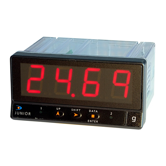
- Page 1 DIGITAL PANEL VOLTMETER JUNI OR-VAC JUNI OR20-VAC...
- Page 2 The KOSMOS SERIES brings a new phylosophy in digital Other features of the KOSMOS family include : panel instrumentation which is expressed by multipurpose, modular-concept devices providing a rich array of basic CONNECTIONS via plug-in terminal blocks without functions and advanced capabilities.
-
Page 3: Table Of Contents
DIGITAL PANEL METER JUNIOR FAMILY JUNI OR-VAC & JUNI OR20-VAC INDEX 1. GENERAL INFORMATION MODELS JR/ JR20-VAC ......................4-5 1.1. DISPLAY AND KEYBOARD DESCRIPTION....................6-7 2 . OPERATING INSTRUCTIONS ............................8 2.1 - POWER SUPPLY AND CONECTIONS ......................9-10 2.2 - PROGRAMMING INSTRUCTIONS........................11 2.3 - DEVICE CONFIGURATION ...........................12 2.4 - INPUT CONNECTION ..........................14 INPUT CONFIGURATION ..........................15... -
Page 4: General Information Models Jr/ Jr20-Vac
2RE OUTPUT OPTION FRONT COVER MAIN BOARD CASE WITH PANEL FIXING CLIPS DISPLAY AND KEYBOARD MODULE... - Page 5 1. JUNIOR-VAC and JUNIOR20-VAC MODELS This manual talks about the Junior-VAC and Junior20-VAC The basic instrument is a soldered assembly composed of the main board, and the display and keyboard module. models. Both instruments, small format, have a 4 digits display Optionally, it can be equipped with a 2-relay control output (0/9999) and are used to measure Volts AC.
- Page 6 FRONT-PANEL FUNCTIONS DESCRIPTION (RUN MODE) KEYBOARD IN RUN SHIFT DATA MODE LABEL ENTER Engineering units. LED SET1 LED SET2 Indicates setpoint 1 status. Indicates setpoint 2 status. KEY UP Disabled in run mode. TOUCHE DATA Appel des données KEY SHIFT Passage en mode PROG Disabled in run mode.
- Page 7 FRONT-PANEL FUNCTIONS DESCRIPTION (PROG MODE) SHIFT DATA KEYBOARD IN PROG LABEL MODE ENTER Engineering units LED SET1 LED SET2 Indicates programming Indicates programming of the setpoint1. of the setpoint2. Gives access to the setpoint values. KEY ENTER Increments the active digit Validates programmed data.
-
Page 8: Operating Instructions
2. OPERATING INSTRUCTIONS PACKING CONTENTS Programming instructions (page 11) Instructions manual in English including Declaration of Conformity. The software inside the instrument allows configuring the The digital panel instrument JR/ JR20-VAC. input and display parameters. If a two-relay output option Accessories for panel mounting (sealing gasket and fixing is installed ref. -
Page 9: Power Supply And Conections
2.1 - Power supply and connectors To change the meter s physical configuration remove the case as shown in figure 9.1. 115/230 V AC: The instruments with 115/230 V AC power are set up at fabrication for 230 V AC (USA market 115 V AC), see figure 9.2. - Page 10 POWER CONNECTION If not installed and used in accordance with these instructions, protection against hazards may be impaired. WARNING In order to guarantee the electromagnetic compatibility, the following guidelines should be kept in mind : Power supply wires may be routed separated from signal wires. Never run power and signal wires in the same conduit.
-
Page 11: Programming Instructions
Programming Instructions To enter in the programming mode Connect the meter to the mains supply, for approx. 1s a self-test routine automatically activates all the digits of the display. After, the instrument goes to the normal operating mode (RUN). ENTER To enter in the programming mode press and the the indication Pro shown in figure 11.1 appears on the display. -
Page 12: Device Configuration
2.3 - Instrument configuration < 2s Direct setpoints With 2 setpoints option SHIFT DATA ENTER value programming SHIFT DATA SHIFT DATA ENTER ENTER SHIFT DATA ENTER SHIFT DATA ENTER SHIFT DATA SHIFT DATA SHIFT DATA SHIFT DATA ENTER ENTER ENTER ENTER SHIFT DATA... - Page 13 Display programming (comes from page 12). SHIFT DATA SHIFT DATA ENTER ENTER SHIFT DATA SHIFT DATA ENTER ENTER SHIFT DATA ENTER SHIFT DATA SHIFT DATA ENTER ENTER 2s o 2s o Edit with SHIFT DATA SHIFT DATA ENTER ENTER SHIFT DATA SHIFT DATA...
-
Page 14: Input Connection
Input connection Refer to the transducer connection schematics and the connection recomendations on page 10. Input signal connection (CN2) PIN 1 = IN (common) PIN 2 = IN [20.00V AC] PIN 3 = IN [200.0V AC] PIN 4 = Non connected PIN 5 = IN [600V AC] Input signal connection depending on the desired range IN (20V) -
Page 15: Input Configuration
ACCESS TO THE PROGRAMMING MODE [15.1] Programming mode Connect the instrument to the main supply, it automatically enters in a self-test routine which briefly illuminates all segments and LED s then shows the software version and finally goes to the normal reading ("RUN" mode). Press ENTER to access the programming mode. -
Page 16: Display Configuration
Display configuration Direct mode: If input signal increases display reading increases. After the input configuration it is necessary to program the If input signal decreases display reading decreases. display range to adapt the meter to the particular application in the desired units. In programmation menus for display configuration first will be Display range should be between -1999 and 9999. - Page 17 [17.1] Display menu ENTER From the "Pro" indication, press and by pressing the key, select the display configuration menu (fig. 17.1). ENTER to access to the display configuration SHIFT DATA ENTER [17.2] Configuration method The figure 17.2 shows the indication corresponding to the display range configuration method.
- Page 18 [18.1] Display 2 value The figure 18.1 shows the indication "DsP2" during 2s before programming the display value for point 2 (Dsp2). The display shows any numerical value with the first digit blinking. To modify the value (range from -1999 to 9999), press the key to change the active digit and key to go to the next digit.
-
Page 19: Relais Configuration
2.7 SETPOINT CONFIGURATION (accessible if 2RE option is installed) If a two relay option is installed (see page 23) the instrument will allow to enter on the following routines: activation mode, delay or hysteresis and setpoint program lockout. From the Pro stage (see fig. 15.1), press the key to access to the setpoint ENTER configuration module, indication "SET". - Page 20 [20.1] Setpoint 2 Configuration The indication shown in figure 20.1 appears on the display to indicate that the next step is to program the setpoint 2 operating parameters (led Setpoint 2 activated). ENTER After 2 seconds or by a press of , the meter allows access to this menu.
- Page 21 [21.1] Setpoints Programming ENTER To program the setpoint values, press to access the programming mode (indication Pro, figure 21.1) and press to make the display show the previously programmed value of setpoint 1. NOTE: The setpoint values should be programmed within the selected measurement range.
-
Page 22: Programming Lockout
2.8 - Programming lockout After completing the instrument s programming, it is recommended to lockout the access to the programming to prevent from accidental or unauthorized modifications. This operation is made by taking off a plug-in jumper located on the main board circuit (see figure at right). NOTE : Disconnect power before changing the jumper position. -
Page 23: Relay Option
3. RELAY OUTPUT OPTION As an option, the JUNIOR-VAC models can be equipped with the following output option: A control output card with two SPDT relay outputs rating 8 A @ 250 V AC / 150 V DC. The outputs can be programmed for HI or LO operation and selectable time delay or hysteresis action. -
Page 24: Technical Specifications
4. SPECIFICATIONS TECHNIQUES INPUT SIGNAL DISPLAY Configuration......differential asymmetrical Type ........0/ 9999, 4 red digits 14 mm Input ........600V ..200V ... 20V Junior-VAC ........4 digits, 14mm high Resolution (internal) ... 39mV ..13mV ..10mV Junior20-VAC........4 digits, 20mm high Input Impedance .... -
Page 25: Dimensions And Mounting
4.1 - Dimensions and mounting To install the instrument into the panel, make a 92x45mm cutout and insert the instrument from the front placing the sealing gasket between this and the front bezel. Place the fixing clips on both sides of the case and slide them over the guide tracks until they touch the panel at the rear side. -
Page 26: Warranty
All the DITEL products benefit from an unlimited and unconditional warranty of THREE (3) years from the date of their purchase. Now you can extend this period of warranty up to FIVE (5) years from the product commissioning, only by fulfilling a form. -
Page 27: Declaration Of Conformity
6 - DECLARATION OF CONFORMITY Manufacturer : DITEL - Diseños y Tecnología S.A. Applicable Standards : EN50081- 1 Generic emission EN55022/CISPR22 Class B Address : Travessera de les Corts, 180 Applicable Standards : EN50082- 1 Generic inmunity 08028 Barcelona IEC1000-4-2... - Page 28 DISEÑOS Y TECNOLOGIA, S.A. Polígono Industrial Les Guixeres C/ Xarol 8 C 08915 BADALONA-SPAIN Tel : +34 - 93 339 47 58 Fax : +34 - 93 490 31 45 E-mail : dtl@ditel.es www.ditel.es...
Need help?
Do you have a question about the KOSMOS Series and is the answer not in the manual?
Questions and answers