Ditel KOSMOS Series Manual
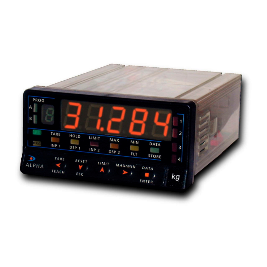
Digital panel instrument for use with load cell
Hide thumbs
Also See for KOSMOS Series:
- Instruction manual (56 pages) ,
- Manual (51 pages) ,
- User manual (31 pages)
Table of Contents
Advertisement
Quick Links
Advertisement
Table of Contents

Subscribe to Our Youtube Channel
Related Manuals for Ditel KOSMOS Series


Summary of Contents for Ditel KOSMOS Series
- Page 1 DIGITAL PANEL INSTRUMENT FOR USE WITH LOAD CELL JUNI OR-LCC JUNI OR20-LCC...
- Page 2 The KOSMOS SERIES brings a new philosophy in digital panel Other features of the KOSMOS family include: instrumentation, which is expressed by multipurpose, modular-concept devices providing a rich array of basic CONNECTIONS via plug-in terminal blocks without functions and advanced capabilities.
-
Page 3: Table Of Contents
DIGITAL PANEL INSTRUMENT JUNIOR FAMILY JUNI OR-LCC & JUNI OR20-LCC INDEX 1. MODELS JR/ JR20-LCC OVERVIEW ..........................4-5 1.1. FRONT-PANEL DESCRIPTION ........................6-7 2. SET-UP AND OPERATION ............................... 8 2.1 - POWER SUPPLY AND CONNECTORS ......................9-10 2.2 - PROGRAMMING INSTRUCTIONS .........................11 2.3 - INSTRUMENT SET-UP ..........................12 2.4 - INPUT CONNECTION 13 2.5 - INPUT CONFIGURATION and LOCK TARE KEY..................14-15... -
Page 4: Models Jr/ Jr20-Lcc Overview
2RE OUTPUT OPTION FRONT COVER MAIN BOARD CASE WITH PANEL FIXING CLIPS DISPLAY AND KEYBOARD MODULE... - Page 5 1. MODELS JUNIOR-LCC and JUNIOR20-LCC This manual describes the models Junior-LCC and Junior20- The basic instrument is a soldered assembly composed of the main board, and the display and keyboard module. LCC both instruments are small format. The difference between both models is the size of the digits of Optionally, it can be equipped with a 2-relay control output the display.
-
Page 6: Front-Panel Description
FRONT- PANEL FUNCTIONS DESCRIPTION (RUN MODE) TECLADO EN MODO SHIFT DATA DE TRABAJO LABEL ENTER Engineering units. LED SET1 LED SET2 Indicates setpoint 1 status. Indicates setpoint 2 status. KEY UP TARE. KEY DATA Shows programming data. KEY SHIFT Gives access to PROG mode. Disabled in run mode. - Page 7 FRONT- PANEL FUNCTIONS DESCRIPTION (PROG MODE) SHIFT DATA KEYBOARD IN PROG LABEL MODE ENTER Engineering units LED SET 2 LED SET1 Indicates programming of the Indicates programming of the setpoint 1. setpoint 2. Gives access to the setpoint values. Increments the active digit value. KEY ENTER Validates programmed data.
-
Page 8: Set-Up And Operation
2. OPERATING INSTRUCTIONS PACKING CONTENTS Programming instructions (page 11) Instructions manual in English including Declaration of Conformity. The software inside the instrument allows configuring the The digital panel instrument JR/ JR20-LCC. input and display parameters. If a two-relay output option Accessories for panel mounting (sealing gasket and fixing is installed ref. -
Page 9: Power Supply And Connectors
Power supply and connectors To change the meter s physical configuration remove the case as shown in figure 9.1. 115/230 V AC: The instruments with 115/230 V AC power are set up at fabrication for 230 V AC (USA market 115 V AC), see figure 9.2. - Page 10 POWER CONNECTION INSTALLATION To meet the requirements of the directive EN61010-1, where the unit is permanently connected to the mains supply it is obligatory to install a circuit breaking device easy reachable to the operator and clearly marked as the disconnect device. WARNING In order to guarantee the electromagnetic compatibility, the following guidelines should be kept in mind:...
-
Page 11: Programming Instructions
Programming Instructions To enter in the programming mode Connect the meter to the main supply, for approx. 1s a self-test routine automatically activates all the digits of the display. After, the instrument goes to the normal operating mode (RUN). To enter in the programming mode press for 5 seconds until the indication Pro shown in figure 11.1 appears on the display. To exit from the programming mode To return to the run mode, it is necessary to pass through the different menu steps by successively pressing the ENTER... -
Page 12: Instrument Set-Up
2.3 - I nstrument s setup The enclosed diagram shows the complete programming routines for models JR/ JR20-LCC. The basic parameters, which refer to the input and display configurations, are organized into two modules: "InP" and "dSP". If a 2-relay option is installed (see page 27), the module "Set", that allows configuring the option, is automatically included in the... -
Page 13: Input Connection
INPUT connections Check the transducers connections diagrams and the recommendations on Page 10. INPUT SIGNAL CONNECTION (CN2) PIN 1 = -IN (signal negative) PIN 2 = +IN [30 mV, 300 mV] PIN 3 = TARE PIN 4 =+EXC (excitation positive) PIN 5 = -EXC (excitation negative)/ TARE Connection for one LOAD CELL Connection for more... -
Page 14: Input Configuration And Lock Tare Key
START PROGRAMMING [14.1] Programming mode After plug-in the power supply according to indicated on the instrument s label, automatically, will do a test activating all segments of display. Next will show the software version and after that the instruments goes to RUN" mode. ENTER Press key to enter in programming mode. - Page 15 [15.1] Lock TARE function The figure 15.1 shows the indication corresponding to the TARE lock function by the , not the remote the always remains active. If needed to modify this parameter, press key until appears on display the desired option [LC O = lock disabled or LC 1 = lock enabled] ENTER Press...
-
Page 16: Display Configuration
Display configuration Forward operation: After configuring and connecting the input sensor is When input signal increases, the display increases. necessary to program the display range in order to get When input signal decreases, the display decreases. readings in the desired engineering units. Reverse operation: When input signal increases, the display decreases. - Page 17 [17.1] Display menu ENTER From the indication "Pro", press and select by key, the configuration display menu (Figure. 17.1) ENTER Access to display configuration. NOTE: Before proceeding to scale the instrument the TARE memory have to SHIFT DATA be erased. (See if the most right decimal point is blinking) ENTER [17.2] Configuration method The figure 17.2 shows the indication (SCAL) corresponding to entry stage into the...
- Page 18 [18.1] Display 1 value On figure 18.1 the indication "dSP1" will be present for 2 s before passing to program the display value for point 1 (dSP 1) The display will show a numerical value (according last programmed) with the firs digit left flashing.
-
Page 19: Setpoints Configuration
2.7 SETPOINT CONFIGURATION (accessible if 2RE option is installed) If a two-relay option is installed (see page 23) the instrument will allow entering on the following routines: activation mode, delay or hysteresis and setpoint program lockout. From the Pro stage (see fig. 15.1), press the key to access to the setpoint ENTER configuration module, indication "SET". - Page 20 [20.1] Setpoint 2 Configuration The indication shown in figure 20.1 appears on the display to indicate that the next step is to program the setpoint 2 operating parameters (led Setpoint 2 activated). ENTER After 2 seconds or by a press of , the meter allows access to this menu.
- Page 21 [21.1] Setpoints Programming ENTER To program the setpoint values, press to access the programming mode (indication Pro, figure 25.1) and press to make the display show the previously programmed value of setpoint 1. NOTE: The setpoint values should be programmed within the selected measurement range.
-
Page 22: Programming Lockout
Programming lockout After completing the instrument s programming, it is recommended to lockout the access to the programming to prevent from accidental or unauthorized modifications. This operation is made by taking off a plug-in jumper located on the main board circuit (see figure at right). NOTE: Disconnect power before changing the jumper position. -
Page 23: Setpoints Option
3. RELAY OUTPUT OPTION As an option, the Jr/Jr20-LCC models can be equipped with the following output option: A control output card with two SPDT relay outputs rating 8 A @ 250 V AC / 150 V DC. The outputs can be programmed for HI or LO operation and selectable time delay or hysteresis action. -
Page 24: Technical Specifications
4. TECHNICAL SPECIFICATIONS INPUT SIGNAL A/D CONVERSION Configuration ......differential asymmetrical Technique ........... Sigma-Delta Input ........± 30 mV..... ± 300 mV Resolution ............±15 bits Resolution........5 V....10 V Rate..............25/ s Input impedance ....100 M ....100 M Filter (cut-off frequency @ 3 dB) ....... 1,20 Hz DISPLAY Type ...... -
Page 25: Dimensions And Mounting
4.1 - Dimensions and mounting To install the instrument into the panel, make a 92 x 45 mm cutout and insert the instrument from the front placing the sealing gasket between this and the front bezel. Place the fixing clips on both sides of the case and slide them over the guide tracks until they touch the panel at the rear side. -
Page 26: Warranty
All the DITEL products benefit from an unlimited and unconditional warranty of THREE (3) years from the date of their purchase. Now you can extend this period of warranty up to FIVE (5) years from the product commissioning, only by fulfilling a form. -
Page 27: Declaration Of Conformity
6 - DECLARATION OF CONFORMITY Manufacturer : DITEL - Diseños y Tecnología S.A. Applicable Standards: EN50081- 1 Generic emission EN55022/CISPR22 Class B Address: Travessera de les Corts, 180 Applicable Standards: EN50082- 1 Generic immunity 08028 Barcelona IEC1000-4-2 Level 3 Criteria B ESPAÑA... - Page 28 DISEÑOS Y TECNOLOGIA, S.A. Polígono Industrial Les Guixeres C/ Xarol 8 C 08915 BADALONA-SPAIN Tel : +34 - 93 339 47 58 Fax : +34 - 93 490 31 45 E-mail : dtl@ditel.es www.ditel.es...
Need help?
Do you have a question about the KOSMOS Series and is the answer not in the manual?
Questions and answers