Ditel KOSMOS Series User Manual
Universal digital indicator for process, temperature and resistance input signal
Hide thumbs
Also See for KOSMOS Series:
- Instruction manual (56 pages) ,
- Manual (51 pages) ,
- User manual (31 pages)

Subscribe to Our Youtube Channel
Related Manuals for Ditel KOSMOS Series


Summary of Contents for Ditel KOSMOS Series
- Page 1 JR-P / JR20-P USER MANUAL JUNIOR JR-P / JR20-P UNIVERSAL DIGITAL INDICATOR FOR PROCESS, TEMPERATURE AND RESISTANCE INPUT SIGNAL KOSMOS SERIE www.ditel.es...
-
Page 2: Table Of Contents
JR-P / JR20-P INDEX GENERAL INFORMATION Package contents ......................4 Recycling instrucctions ....................4 General safety considerations ..................4 Symbols identification ....................4 Maintenance ........................5 Warranty ........................5 Conformity declaration ....................6 Device description ......................7 Dimensions and mounting ....................7 Display and keyboard ..................... -
Page 3: Index
JR-P / JR20-P INDEX SPECIFICATIONS Technical specifications ....................25 KOSMOS SERIE... -
Page 4: General Information
JR-P / JR20-P GENERAL INFORMATION This manual does not constitute a contract or a commitment on the part of Diseños y Tecnología, S.A. All information contained in this document is subject to change without prior notice. MANUAL VALID FOR INSTRUMENTS WITH P2.02 SOFT VERSION OR HIGHER Package contents With the instrument it is also supplied: ... -
Page 5: Maintenance
All DITEL products benefit from an unlimited and inconditional warranty of three (3) years from the date of their purchase. Now you can extend this period up to five (5) years from the product commissioning, only by fulfilling the corresponding form. -
Page 6: Conformity Declaration
JR-P / JR20-P Conformity declaration EN 61326-1 Electrical equipment for measurement, control and laboratory use (EMC) EN 61000-4-2 Electrostatic discharge (ESD) Criterion B Air discharge 8kV Contact discharge 4kV EN 61000-4-3 Electromagnetic fields Criterion A 10 V/m EN 61000-4-4 Fast transients (burst) Criterion B Power lines 2 kV... -
Page 7: Device Description
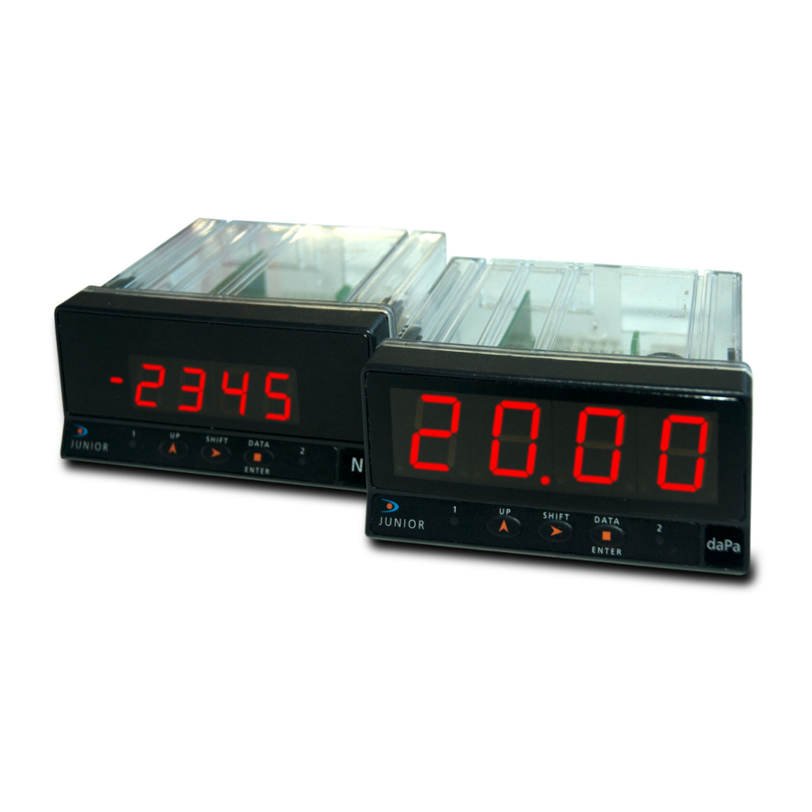
JR-P / JR20-P Device description All information contained in this manual, unless indicated, is valid for both JR-P and JR20-P m odels. JR-P and JR20-P m odels from K OSM OS serie are universal digital indicators fully configurables that allow input type selection in order to be used as needed. Available signal inputs are the following: PROCESS (V, m A) THERMOCOUPLE (J, K , T y N ) Pt100 and Pt1000 SENSOR... -
Page 8: Display And Keyboard
JR-P / JR20-P Display and keyboard There are two main function modes: RUN and PRO. PRO m ode is w hen configuration menu is entered to programm indicator, whereas RUN is the norm al m ode in w hich display shows the reading according to configuration and input signal value. -
Page 9: Connections
JR-P / JR20-P Connections Rear connectors location. Basic instrument has two rear connectors CN1 and CN2. If 2RE output option card is installed, two more connectors CN3 and CN4 appear. See all four connectors location and their pin out in the right figure. -
Page 10: Process Input (Ma)
JR-P / JR20-P 3 WIRES CONNECTION WITH EXCITATION SUPPLIED BY THE INDICATOR 3 WIRES CONNECTION WITH EXTERNAL EXCITATION INDICATOR TRANSDUCER INDICATOR TRANSDUCER 0-10V 0-10V 0-200V 0-200V +OUT -OUT +EXC. +OUT -OUT +EXC. COM. +EXC. COM. EXC. Process input signal wiring diagrams (mA) 4 WIRES CONNECTION WITH EXTERNAL EXCITATION 4 WIRES CONNECTION WITH EXCITATION SUPPLIED BY THE INDICATOR INDICATOR... -
Page 11: Pt100 And Pt1000 Sensor Input
JR-P / JR20-P Pt100 and Pt1000 sensor input wiring diagram (ºC) Pt100 SENSOR INDICATOR Pt1000 SENSOR INDICATOR Pt100 COM. Pt100 Pt1000 Pt100 Pt1000 Thermocouple J, K, T and N input wiring diagram (ºC or ºF) INDICATOR J,K,T,N Resistance input wiring diagram () INDICATOR INDICATOR 10k... -
Page 12: Input Configuration
JR-P / JR20-P INPUT CONFIGURATION Configuration menu When connecting instrument to Power supply, display test begins automatically to check the good function of LED’s and digits, once this test is finished, display shows internal software version and then the unit goes to RUN mode. Configuration software has a hierarchical structure composed of a number of menus and submenus. -
Page 13: Process
JR-P / JR20-P Process ProC The parameters to be configured in input process submenu are: INPUT TYPE: V DC: ±10V or ±200V (-tachometric dynamo-) ±20mA (single range, direct validation) 200U Temperature tEMP The parameters to be configured in input temperature submenu are: SENSOR TYPE: Termocouple J(1), K(2), T(3) or N(4) Pt1: Pt100 sensor (direct validation) -
Page 14: Resistance
JR-P / JR20-P Resistance The only parameter to be configured in input temperature submenu is: RESISTANCE RANGE: 999.9: 999.9 (1k) Range 9999: 9999 (10k) Range 50.00: 50.00k (50k) Range KOSMOS SERIE... -
Page 15: Display Configuration
JR-P / JR20-P DISPLAY CONFIGURATION Display Programming The second menu corresponds to display configuration. This, in turn, consists of some submenus according to previously programmed input type: through frontal keys configuration (SCAL or uSEr), through real input signal (TEACH) (tEAC), calibrated range ( CAL) and reading stabilization filter ( FiLt). TRHOUGH FRONTAL KEYS CONFIGURATION “SCAL”... -
Page 16: Process Input
JR-P / JR20-P Process input When programmed input type is process, for both display scaling SCAL tEAC “SCAL” and “tEAC” methods, parameters to be sequentially introduced are identical. It only must be considered that in “SCAL” method, all values must be manually introduced through the three frontal keys whereas in “tEAC”... -
Page 17: Potentiometer Input
JR-P / JR20-P Potentiometer input When programmed input type is potentiometer, “tEAC” is the only method available to perform display scaling. In this case, it must be assured first that potentiometer is connected properly and that it is not subjected to any external voltage. tEAC After pressing ENTER key, the instrument analyzes connected potentiometer to internally determine both maximum and minimum resistive values. -
Page 18: Setpoints Configuration
JR-P / JR20-P SETPOINTS CONFIGURATION Setpoints configuration The third menu “SEtP” only appears when two relays output card is SEtP installed. For further details on function modes please refer to the corresponding OUTPUT OPTION part later on this manual. Programming steps are equal for both relays on each “SEt1” and “SEt2”... -
Page 19: Available Keyboard Functions
JR-P / JR20-P AVAILABLE KEYBOARD FUNCTIONS In addition to already known functions used to browse through the configuration menus and submenus, introduce and/or modify existing values and parameters, the instrument provides some more added functions. MAX/MIN and RESET functions This device detects and stores in memory maximum and minimum values reached by the input signal. This values are kept in memory although power supply is desconnected. -
Page 20: Access To Lock-Out Configuration Menu
JR-P / JR20-P Access to lock-out configuration menu To access this menu from RUN mode, press ENTER key for at least 3 seconds. 8888 Display shows now “CodE” and then “0000”. Desired security code must be introduced through SHIFT and UP keys (by default this code is 0000). CodE Finally press ENTER to begin with lock-out level configuration. -
Page 21: Configuration Lock-Out
JR-P / JR20-P CONFIGURATION LOCK-OUT Lock-out menu In order to prevent accidental or indesirable modifications of instrument parameters, a selective or total configuration lock-out is available. By default the unit is delivered unlocked, giving access to all programming levels. Once in this menu, the first option will be to choose between lock-out level setting (“LiSt”) or security access code changing (“CHAn”). - Page 22 JR-P / JR20-P Now it is posible to configure SHIFT key lock-out for MAX/MIN function in the same way as previous configurations. When lock-out is enabled (selecting “yES”) it is not possible to visualize maximum or minimum values by pressing SHIFT key, although instrument internally continues detecting and saving new extreme values reached by input signal.
-
Page 23: Output Option
JR-P / JR20-P OUTPUT OPTION Description 2RE output option allows JR-P and JR20-P models to perform control operations and limit values treatment via ON/ OFF logic outputs. It is supplied as an independent card that is connected to main board without any additional operation since internal software recognizes it once it is installed. -
Page 24: Installation
JR-P / JR20-P Installation To physically install the output option, the electronics assembly should be first lifted out from the case. Use a screwdriver or similar to slightly press both side tabs until the rear case is released. Then broke the junctions from the corresponding polycarbonate cover in order to obtain the required orifice in the case. - Page 25 JR-P / JR20-P SPECIFICATIONS Technical specifications TEMPERATURE SPECIAL FUNCTIONS Pt100 measurement current ..........1mA Return to factory configuration. Pt1000 measurement current ......... 100A Software configuration lock-out. Pt100 maximum wire resistance ....... 40 (balanced) PRECISION Pt100/Pt1000 linearization ........IEC 60751 Temperature coefficient ........100 ppm/ºC Pt100/Pt1000 ...
- Page 26 JR-P / JR20-P RESISTANCE 999.9 range max. measurement current ...... 2.3mA 9999 range max. measurement current ....... 230A 50.00k range max. measurement current ...... 23A EMI max. Influence (999.9) ........±0.7 EMI max. Influence (9999) ..........±2 EMI max. Influence (50.00k) ........±20 RANGE RESOLUTION ACCURACY...
- Page 27 JR-P / JR20-P NOTES: INSTRUMENT CONFIGURATION Use the following template for the annotation of configured parameters in your instrument for later consulting or data recover. INPUT: TYPE: RANGE: DISPLAY: CONFIG. MODE: SCAL TEACH INPUT 1: DISPLAY 1: INPUT 2: DISPLAY 2: FILTER (0 ÷...
Need help?
Do you have a question about the KOSMOS Series and is the answer not in the manual?
Questions and answers