Ditel KOSMOS Series Manual
Instrument for use with load cell
Hide thumbs
Also See for KOSMOS Series:
- Instruction manual (56 pages) ,
- User manual (31 pages) ,
- Manual (28 pages)
Table of Contents
Advertisement
Advertisement
Table of Contents

Related Manuals for Ditel KOSMOS Series


Summary of Contents for Ditel KOSMOS Series
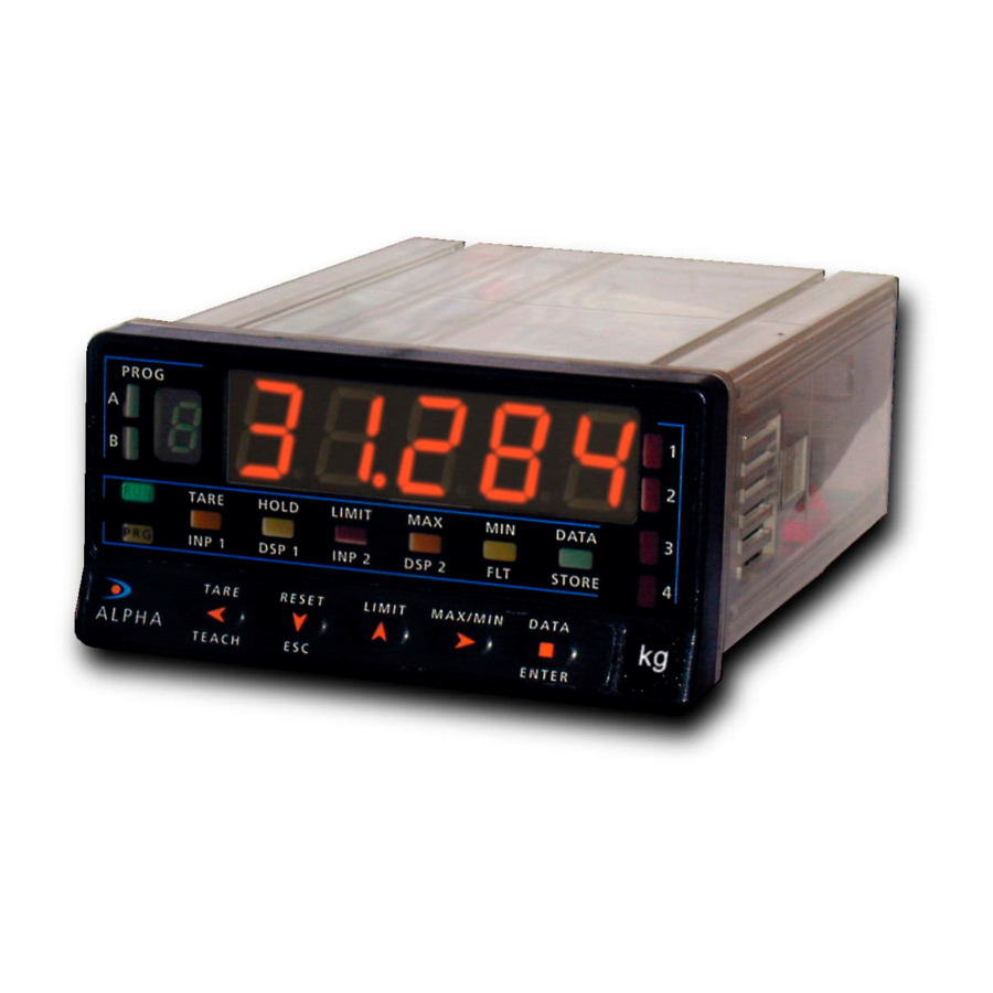
- Page 1 MODEL ALPHA-C INSTRUMENT FOR USE WITH LOAD CELL...
- Page 2 Firmware Version 2.00 Blinking Display See page 41 Modbus Compatible Programming parameters lockout See page 44 See page 38 Fail Safe Function Factory defaults See page 42 See page 43 Sensor Break Alarm Linearization by segments See page 29 See page 16 3 Tare modes 36 Logical functions See page 26...
- Page 3 All information given in this manual is subject to following structured choice menus aided by display prompts change without notice. at each programming step. The KOSMOS SERIES brings a new philosophy in digital panel Other features of the KOSMOS family include: instrumentation which...
- Page 4 INDEX 1 . MODEL ALPHA-C OVERVIEW ............................. 6 1.1. - KEYBOARD AND DISPLAY DESCRIPTION ..................... 7 2 . GETTING STARTED ..............................9 2.1 - POWER / CONNECTORS..........................10 2.2 - INTRODUCTION TO THE PROGRAMMING MODE ..................12 2.3 - INPUT CONFIGURATION..........................14 2.4 - DISPLAY CONFIGURATION .........................16 2.5 –...
- Page 5 BCD OUTPUT BOARD RS232C or RS485 OUTPUT BOARD ANALOG OUTPUT BOARD SETPOINTS OUTPUT BOARD INPUT BOARD CASE WITH POWER FIXING CLIPS FILTER CIRCUIT FRONT-PANEL COVER DISPLAY MAIN BOARD...
- Page 6 The model ALPHA-C of the KOSMOS series is a digital indicator In addition, a variety of plug-in output cards can be installed at designed to measure forces (weight, load, torque, pressure ...)
- Page 7 FRONT-PANEL FUNCTIONS IN RUN MODE MAIN DISPLAY Reads the input variable AUXILIARY DISPLAY Positive " " or LED 1 negative "-" signal Indicates activation/display setpoint 1 PROG LED 2 RUN LED Indicates activation/display setpoint 2 RUN mode indication LED 3 TARE LED R UN TAR E...
- Page 8 FRONT-PANEL FUNCTIONS IN PROG MODE MAIN DISPLAY Reads programming parameters AUXILIARY DISPLAY Indicates program module FLT LED PROG Indicates input filter programming A and B LED's Indicates program module letter STORE LED Indicates exit from the program mode with data R UN TAR E HO LD...
-
Page 9: Getting Started
2. GETTING STARTED PACKAGE CONTENTS Programming instructions (page 11 and 12) Instructions manual in English including Declaration of The software is divided into several independently Conformity. accessible modules to configure the input, the display, the D.P.M. model Alpha-C2.00. setpoints, analogical output, output Accessories for panel mounting (sealing gasket and... -
Page 10: Power Supply
2.1 - POWER SUPPLY Should any hardware modification be performed, remove the electronics from the case as shown in figure 9.1. 115/230 V AC: The instruments with 115/230 V AC power, are shipped from the factory for 230 V AC (USA market 115 V AC), see figure 9.2. -
Page 11: Power Connection
POWER CONNECTION INSTALLATION To meet the requirements of the directive EN61010-1, where the unit is permanently connected to the mains supply it is obligatory to install a circuit breaking device easily reachable by the operator and clearly marked as the disconnect device. WARNING In order to guarantee electromagnetic compatibility, the following guidelines for cable wiring must be followed:... -
Page 12: Programming Instructions
2.2 - PROGRAMMING INSTRUCTIONS Connect the instrumento to the main supply. During a short The 3, 4 and 5 modules will be bypassed if the output options period of time the digits, the decimal point and LEDs will turn are not installed. The information related to its programming on as a verification of the correct function of the instrument. - Page 13 The programming instructions are composed by a general description and a series of step-by-step instructions to be followed sequentially. Each menu step is represented by an illustration of the display and keyboard module with indicators (display and LED's), reference [page number. figure number] and a text describing the action of each key at that step. [Page nº/figure nº] Mnemo In the step-by-step instructions, you are given the action of the three buttons mainly used to program data.
-
Page 14: Input Configuration
2.3 - INPUT CONFIGURATION Fig. 14.1: excitation jumper To completely configure the input of the load-cell indicator, it will be necessary to act on these two parameters: 1. Excitation voltage selection. The indicator provides two excitation voltages to supply the transducer; 5 V or 10 V. The selection is made by means of a plug-in jumper located behind the input card connector. - Page 15 3. Input programming range. The only configurable parameter is the input range. There are four available ranges; 15 mV, 30 mV, 60 mV or 300 mV which are to be chosen to match the cell sensitivity (max. output in mV). The maximum voltage applicable to the instrument is 300 mV. The built-in excitation voltage can be used to power up to 4 cells connected in parallel, with 10 V excitation and up to 8 cells with 5 V excitation.
-
Page 16: Display Configuration
2.4 - DISPLAY CONFIGURATION Fig. 16.1: Linearizing After selection of the input range, it may be necessary to (inp7, dsp7) function with 6 scale the instrument for the particular application. For many (inp6, dsp6) segments (7 points). common applications, single slope scaling (2 points) should (inp5, dsp5) (inp4, dsp4) be sufficient to have good readings over the entire process... - Page 17 3. Scaling the indicator. After deciding the values for INPUT and DISPLAY and the decimal point position, we are ready to enter in the display configuration module. It has six configurable menus: scaling, balanced filter, damping filter, round filter, tare and sensor break detection.
- Page 18 MENU 2A - SCALE This menu allows programming the necessary parameters to determine the display range (INP1 - DSP1 - Decimal Point - INP2 - DSP2 - INP3 - DSP3 -…). As a default, these values are expected to be introduced by keyboard. To use the actual signal input values as INP# parameters, it is sufficient to push on the key at INPUT programming phases.
- Page 19 [19.1] Decimal point Programming the decimal point which apears blinking. Press repeatedly the key to move it to the right until desired position. Si If no decimal point is required, it must be placed to the right side of the display. The PROG decimal point remains in the selected position in all programming phases and the run mode.
- Page 20 [20.1] Point 3 1 second flag indication for scaling point 3 Multi-slope scaling sequence begins at this step. PROG TARE HOLD LIMIT DATA Programming the input value at point 3, led INP2 on. INP1 DSP1 INP2 DSP2 STORE Key-in method: Use to switch between "0"...
- Page 21 [21.1] Point 4 1 second flag indication for scaling point 4. NOTE: The instructions given for programming point 4 are applicable to the PROG programming of points 5 to 30. TARE HOLD LIMIT DATA INP1 DSP1 INP2 DSP2 STORE TARE RESET LIMIT MAX/MIN...
- Page 22 [22.2] Point 30 1 second flag indication for scaling point 30. PROG TARE HOLD LIMIT DATA INP1 DSP1 INP2 DSP2 STORE TARE RESET LIMIT MAX/MIN ENTER TEACH DATA The previously programmed INP30 value appears on the display, LED INP2 activated. [22.2] Input 30 value Key-in method: Select the blinking sign in the auxiliar display with key ["0"...
- Page 23 MENU 2B - BALANCED FILTER The balanced filter acts as a delay on the display response to signal variations produced at the input. The filtering level is programmable from 0 to 9. The effect of incrementing this filter level results in a softer response of the display to the input variations.
- Page 24 MENU 2AB - DAMPING FILTER The damping filter cuts off input values exceeding from the limits of a symmetrical band. This band becomes more selective as the filter level is increased. The filtering level is programmable from 0 to 9. Level 0 disables the filter. [24.1] Damping filter The figure 24.1 shows the indication (FLt-E) corresponding to entry stage of the damping filter menu.
- Page 25 MENU 2AB - ROUND FILTER This menu allows selection among 4 levels of display rounding. When resolution is not critical, a rounding increment higher than 1, may help to stabilize the display. [25.1] Round filter The figure 25.1 shows the indication (round) corresponding to the round menu. Press to access the configurations ENTER PROG...
- Page 26 MENU 2 – MODE TARE In this menu you can configure the mode TARE [26.1] Mode TARE The figure 26.1 displays the text (ModtA) that corresponds to the menu that allows the selection of the mode TARE. Press key to access this menu. PROG ENTER Access the configuration.
- Page 27 With the key we select the tare processing mode of the instrument. When you access this menu, the stored tare value is reset to zero and as always that the instrument is in this state, the Tare LED will be turned off. Once selected the run mode, we exit to the run mode where the tare process will be done.
- Page 28 2.5 – PROGRAMMING NET VALUE IN TARE MODE 3 To edit the net value, being the instrument in RUN mode, press the key to ENTER get the indication –Pro- then press the key more than 3 seconds, showing TARE the display the last TARE value programmed and the most left red digit blinking with key and key program the NET value, usually indicated on the PRESS...
- Page 29 MENU 2 – SENSOR BREAK This function allows detecting any broken wire that connects the sensor “Load Cell” to the instrument. The analysis to detect the broken wires is done every 1.5 seconds and the response of Relays and ANA options (if used) will be the same if it were a overflow (oVFLo) situation, input signal greater than allowed.
-
Page 30: Keyboard Functions
3. KEYBOARD AND REMOTE CONTROLS 3.1 - KEYBOARD FUNCTIONS The front-panel keyboard includes the following function keys: TARE, RESET, LIMIT and MAX/MIN. The functionality of each one, which is available in the "RUN" mode, is described next TARE. A push of this key adds the current display value to LIMIT. - Page 31 MAX/MIN. This key calls up the peak and valley values To erase the peak and/or valley memories, press "MAX/MIN" contained in memory. The first push recalls the maximum one or two times to display the value to be reset. Press and value reached for the variable since the last reset operation hold down the "RESET"...
- Page 32 3.2 - REMOTE FUNCTIONS (CN2) The rear connector CN2 provides 4 user programmable optocoupled inputs that can be operated from external contacts or logic levels supplied by an electronic system. Four different functions may be then added to the functions available from the front-panel keys.
- Page 33 3.3 - TABLE OF PROGRAMMABLE FUNCTIONS • Nº: Function number. • Function: Function name • Description: Description and characteristics of the function. • Activation: Falling edge: The operation is performed on a falling edge applied to the pin with respect to COMMON. Low level: The function remains activated while the corresponding pin is held at a low level with respect to COMMON.
- Page 34 13 to 16: FUNCTIONS ASSOCIATED WITH THE ANALOG OUTPUT Nº Function Description Activation ANA GROSS Makes the analog output follow the gross value (measured value + tare). Low level ZERO ANA Puts the analog output to the zero state (0 V for 0-10 V, 4 mA for 4-20 mA) Low level ANA PEAK Makes the analog output follow the peak value...
- Page 35 29 to 36 : NEW FUNCTIONS Nº Function Description Activation Deactivate Setpoints Deactivates the activity of the setpoints and leaves the outputs at still Low level Batch Adds the present value of the display to the totalizer and increments the Impulse batch counter once.
- Page 36 3.4 - PROGRAMMING THE LOGIC INPUTS After deciding the functions for each connector pin, we are ready to enter in the logic inputs configuration module (6 LoGIn) to effectively programming the logic inputs. [36.1] Logic inputs From the run mode, press to get access to the programming mode (the display ENTER shows -Pro-).
- Page 37 MENU 6A - PIN 1 PROGRAMMING This menu allows selecting the logic function for PIN 1. Available functions are represented by a number from 0 to 36. Consult tables to find the number corresponding to the desired function. The instructions given below apply to pin function 1. Follow the same procedure to configure the rest of the pins.
- Page 38 3.5 – PROGRAMMING LOCK OUT / ACCESS LEVELS In the RUN mode pulse the key during 3 second to accede to the lock ENTER menu (diagram). The instrument has an original lock code which is "0000". By SEt1 rSoUt using the keys, it is possible to enter a new lock CodE.
-
Page 39: Output Options
4. OUTPUT OPTIONS Optionally, the model ALPHA-C can incorporate one or several The options are supplied with a specific instructions manual output options for communications (this output should never describing characteristics, installation, connections be connected to the telephone lines) or control including: programming. - Page 40 The figure shows the different locations of the plug-in output cards. Each location corresponds to a specific function: setpoints, analogical and serial outputs. The options 2RE, 4RE, 4OP and 4OPP are installed in the M5 connector. The ANA option is installed in the M4 connector. The options RS2 and RS4 are installed in the M1 connector.
- Page 41 4.1 NEW FUNCTIONS IN SETPOINT OPTION Available on programming menu 3B-MODE (new function in bold letter) Digit 1 Digit 2 Digit 3 Digit 4 (*) Digit 5 0= OFF 0= HI NO 0= Delay 0= Neto 0= Alarm LED 1= ON 1= LO NO 1= Hyst -1 1= Track Set...
- Page 42 FAIL SAFE Function that allows detecting the power suply fault or an instrument fault and in this way can be informed the PLC or another general system of supervision using the relay option programmed in this way. r.o.C. The function r.o.C (option 9) is useful to detect the changing speed of display value, depending on programmed setpoint polarity we detect the increasing or decreasing.
-
Page 43: Reset Configuration
FUNCTIONS Enable and disable relay / opto (+ LED) by order of RS232C or RS485 RESET CONFIGURATION This feature is programmed by selecting '3 'at the first To restore the factory configuration, press digit of the mode parameter setpoints (3B ModE). ENTER RESET keys at the same time, during 5 seconds. -
Page 44: Serial Output
Commands Resetar valor total RS232 Resetar número de lotes Compatible with ModBus-RTU protocol (see manual ModBus Activar setpoint nº# on www.ditel.es). Desactivar setpoint nº# RS485 Changing parameters Compatible with ModBus-RTU protocol (see manual ModBus Change the value of setpoint # on www.ditel.es). -
Page 45: Technical Specifications
5. TECHNICAL SPECIFICATIONS INPUT SIGNAL DISPLAY • Configuration ......differential asymmetrical • Main ......-32000/32000, 5 digits 14 mm red • • Max Applicable voltage ......±300 mV DC Auxiliary........1 digit 7.62 mm green • Resolution............0.5 µV • Decimal point ........programmable •... -
Page 46: Dimensions And Mounting
5.1 - DIMENSIONS AND MOUNTING To install the instrument into the panel, make a 92x45 mm cut-out and insert the instrument SEALING GASKET FIXING CLIPS into the panel from the front, placing the sealing gasket between this and the front bezel. -
Page 47: Declaration Of Conformity
7. DECLARATION OF CONFORMITY Applicable Standards: EN50081-1 Generic emission Manufacture: DITEL - Diseños y Tecnología S.A. EN55022/CISPR22 Clase B Polígono Industrial Les Guixeres Applicable Standards: EN50082-1 Generic immunity Address: C/ Xarol 8 C IEC1000-4-2 Level 3 Criteria B 08915 BADALONA-SPAIN... - Page 48 NOTES...
- Page 49 NOTES...
- Page 51 INSTRUCTIONS FOR THE RECYCLING This electronic instrument is covered by the 2002/96/CE European Directive so, it is properly marked with the crossed-out wheeled bin symbol that makes reference to the selective collection for electrical and electronic equipment which indicates that at the end of its lifetime, the final user cannot dispose of it as unsorted municipal waste.
Need help?
Do you have a question about the KOSMOS Series and is the answer not in the manual?
Questions and answers