Ditel KOSMOS Series Instruction Manual
Setpoint output option
Hide thumbs
Also See for KOSMOS Series:
- Instruction manual (56 pages) ,
- Manual (51 pages) ,
- User manual (31 pages)
Advertisement
Quick Links
Advertisement

Related Manuals for Ditel KOSMOS Series


Summary of Contents for Ditel KOSMOS Series
- Page 1 INSTRUCTIONS MANUAL SETPOINT OUTPUT OPTION 2 RE- 4 RE 4 OP- 4 OPP...
- Page 2 INTRODUCTION TO THE KOSMOS SERIES Custom CONFIGURATION for specific applications can be made quickly and easily through three or five front panel This manual does not constitute a formal agreement. keys, following structured choice menus aided by display All information given in this manual is subject to prompts at each programming step.
-
Page 3: Output Options
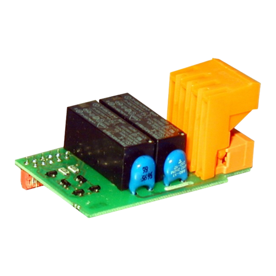
OUTPUT OPTIONS 4OPP INDEX 1 . GENERAL INFORMATION SETPOINTS OPTION......................... 4 2 . SETUP AND CONNECTIONS 2.1 - INSTALLATION ............................5 2.2 - CONNECTION............................6-7 TECHNICAL SPECIFICATIONS ........................7 3 . MODE OF WORKING INDEPENDENT SETPOINTS........................8-9 ASSOCIATED SETPOINTS ..........................9 AUTO-TRACK ............................ - Page 4 1. SETPOINTS OPTION An option of 2 or 4 SETPOINTS, programmable within the full The setpoint option consists of a plug-in additional card that display range, can be incorporated to the unit thus providing once installed to the meter's main board, activates its own alarm and control capabilities by means of individual LED programming module.
-
Page 5: Setup And Connections
2. SETUP AND CONNECTIONS INSTALLATION Lift out the electronics assembly from the case and use a screw-driver to push on the junctions between the case and the shadow areas to detach them from the case. See fig1. The so performed orifice will allow any of the setpoints board output connectors be brought out at the rear of the instrument. - Page 6 2.2 - CONNECTION Fig. 6.1: Rear view of basic instrumment with Relay / Opto NOTE : In case that the outputs are used to drive inductive output option. loads, it is recommended to add an RC network between the CN 7 CN 6 coil terminals (preferably) or between the relay contacts to limit electromagnetic effects.
- Page 7 INSTALLATION TECHNICAL SPECIFICATIONS To meet the requirements of the directive EN61010-1, where the unit is permanently connected to the mains supply it is 2RE OPTION obligatory to install a circuit breaking device easy reachable to the operator and clearly marked as the disconnect device. Max.
-
Page 8: Methods Of Operation
3. METHODS OF OPERATION DESCRIPTION OF OPERATION All the setpoints can operate independently or in association with another in a variety of combinations to suit specific operating conditions. 3.1 INDEPENDENT SETPOINTS. As programmed like independent setpoints, the alarm outputs activate when the display value reaches the user- programmed value. - Page 9 3.2 ASSOCIATED SETPOINTS The figure 1 shows the action of the symmetrical hysteresis. The SET2 and SET4 setpoints can be programmed to "track" In order to clarify the drawing, it has been represented one SET1 and SET3 respectively. This type of alarms does not only alarm in the cases of HI and LO acting.
- Page 10 3.3 AUTO- TRACK In some measurement systems and particularly in Only the alarm 2 provides automatic track function. The auto weighing and dosage applications, the mechanical parts and tracking is implemented by programming SET1 for the the system structure makes it impossible to shut off desired limit value and SET2 for "AUTO TRAC"...
- Page 11 MODELS MI CRA SETPOI NTS PROGRAMMI NG...
- Page 12 MICRAS MODEL PROGRAMMING INSTRUCTIONS T O IN P U T T O D I S P L A Y T O S E R IA L C O N FI G U R A T IO N C O N FI G U R A T IO N O U T P U T M O D U L E M O D U L E...
- Page 13 SETPOINTS PROGRAMMING MODULE DESCRIPTION The diagram represented on page 12 shows the setpoints programming module, which is valid for the MICRA models with 2RE option. Apart from the setpoint values, this option permits the user to program the following parameters : The relays control mode ("HI"...
- Page 14 SETPOINTS PROGRAMMING MENU The setpoint values change can always be accessed from any of the Pro levels even if the RS232C RS485 programming routines are locked out. SET 1 SET 2 The figure 14.1 shows the Pro indication, where the key provides access to the TARE ENTER...
-
Page 15: Setpoint Configuration
SETPOINT CONFIGURATION If a two relay option is installed the instrument will allow to enter on the following routines: activation mode, delay or hysteresis and setpoint program lockout. From programming mode (Pro stage, see fig. 15.1), press key to access to the setpoint configuration, indication "SET". To ENTER program the setpoint numerical values, from the run mode press to call the Pro stage and press... - Page 16 [16.1] Setpoint 2 The indication shown in figure 16.1 appears on the display to indicate that the next step is to program the setpoint 2 operating parameters (led Setpoint 2 activated). RS232C RS485 ENTER After 2 seconds or by a press , the meter allows access to this menu.
- Page 17 SETPOI NTS PROGRAMMI NG MODELS ALPHA...
- Page 18 PROG TARE HOLD LIMIT DATA I NP1 DSP1 INP2 DSP2 STORE RESET LIMIT MAX/MIN DATA MODULE 3 - SETPOINTS TARE TEACH ENTER DEFINITION ENTER The left diagram shows the entire MODULE 3 that allows to program the alarm/ setpoint operation and is PROG activated when one of the following output options 2RE- PROG...
- Page 19 ACCESS TO THE SETPOINTS PROGRAMMING ENTER Press the key to move from the run mode to the programming mode. Press PROG ENTER three time the and press again to access to the programming menus. Each menu activates a different combination of the "A" and "B" LEDs. From this stage, ENTER TARE HOLD...
- Page 20 MENU 3B - OPERATION MODE CONFIGURATION ENTER From the entry stage of the module 3 (Fig. 35.1), press the key to access to PROG the menus and the key to move to the stage of entry into the menu "3B - MODE"...
- Page 21 FAST ACCESS TO THE PROGRAMMING OF THE SETPOINT VALUES Press the ENTER button to move from the run to the programming mode. Press the LIMIT key for fast access to the programming of the setpoint values. The previously programmed setpoint values appear on the display successively at each push of ENTER .
- Page 22 RUN MODE INDICATIONS The ALPHA models provide four LED's for alarm status indication. The LED's are labeled from 1 to 4 although when the 2 relay option (2RE) is installed, only the first PROG two are used. During the normal operation, these indicators are TARE HOLD LIMIT...
- Page 23 4.3 MODEL BETA- M SETPOI NTS PROGRAMMI NG...
- Page 24 MODEL BETA- M PROGRAMMING INSTRUCTIONS S E t P t S - S E t 1 - - S E t 2 - - S E t 3 - - S E t 4 - Only setpoint 2 & 4 - o n - - t r A c - - o F F -...
- Page 25 Menu 30 - Setpoints Access to the setpoints programming The diagram of page 42 corresponds to the menu 30 of ENTER Press to go from run mode to programming mode. setpoints programming that is valid for the output options 2RE, Press to pass to the level shown in the figure.
- Page 26 Submenu 31, 32, 33 & 34 - SETPOINTS [28.1] Start The figure shows the input display in the programming menu of one of the outputs where the symbol "# " represents the setpoint number that you are going to program. To select other setpoint, press until the desired number appears in the place of HOLD...
- Page 27 If you have selected "-on-" in step 28.2 [29.1] Comparison Select comparison of the setpoints with the net value "- nEt- ", with the gross value "- GroS- ", with the peak value "- PEAK- " or with the valley value "- VAL- ". ENTER Validate the introduced data and go to introduce the setpoint value.
- Page 28 If you have selected "-on-" in step 28.2 [30.1] Activation delay The secondary display shows three delay options in the output action. Select one of them: "dLY" = delay or "HYS 1" = asymmetrical hysteresis or "HYS 2" = symmetrical hysteresis. ENTER Validate the selection and go to program the delay value.
- Page 29 If you have selected "-on-" in step 28.2 [31.1] Blink Select "-no- " or "- YES- " to make the main display blink when the setpoint is activated. ENTER Validate the selection and go to the programming access level ("-Pro- "). HOLD Return to the programming access level (indication "-Pro- ").
- Page 30 If you have selected "-trAC-" in step 28.2 [32.1] Activation mode The function "- trAC- " is only available in the SET2 and SET4 alarms. As you can see the auxiliary display shows the number 2 instead of de # ; this is the only alarm that has automatic tracking, by this way, in the SET4 configuration menu, this indication is omitted and you access right to the setpoint value programming) .
- Page 31 DIRECT ACCESS TO THE SETPOINTS VALUE There is an easy way to access only to the setpoints value ENTER configuration. From the run mode (RUN), press , we enter in the programming mode (PROG) and then the key LIMIT ENTER The setpoint values appears by pressing the key .
- Page 32 RUN MODE INDICATIONS The BETA-M has four LED indicators situated at the right side of the display to show the alarm status. The LEDs are numerated from 1 to 4 but with the output option 2RE, only the first two are used. The programmed setpoint values, even if they are inactive, can be visualized during the normal device run mode by pressing HOLD...
- Page 36 DISEÑOS Y TECNOLOGIA, S.A. Polígono Industrial Les Guixeres C/ Xarol 8 C 08915 BADALONA-SPAIN Tel : +34 - 93 339 47 58 Fax : +34 - 93 490 31 45 E-mail : dtl@ditel.es www.ditel.es...
Need help?
Do you have a question about the KOSMOS Series and is the answer not in the manual?
Questions and answers