Ditel Kosmos Series Instruction Manual
Digital panel meter output option rs232c
Hide thumbs
Also See for Kosmos Series:
- Instruction manual (56 pages) ,
- Manual (51 pages) ,
- User manual (31 pages)
Advertisement
Quick Links
Advertisement

Subscribe to Our Youtube Channel
Related Manuals for Ditel Kosmos Series


Summary of Contents for Ditel Kosmos Series
- Page 1 INSTRUCTIONS MANUAL OUTPUT OPTION RS232C...
-
Page 2: Table Of Contents
DIGITAL PANEL METER KOSMOS SERIES OUTPUT OPTI ON RS232C INDEX 1 . OUTPUT OPTION RS232C 1.1. - INTRODUCTION..........................3 1.2. - DESCRIPTION OF OPERATION ....................4 - 6 2 . SETUP AND CONNECTIONS 2.1. - INSTALLATION ..........................7 2.2. - CONNECTION .......................... 8 - 9 3 . -
Page 3: Introduction
9. display, reset of the peak, valley, or tare memories and From the web site www.ditel.es can be downloaded the specific update setpoint values. software that allows to connect the KOSMOS instruments to a... -
Page 4: Description Of Operation
Three communication modes are provided; The ASCII mode utilizes an easy to use protocol, compatible with several models of DITEL instruments. The ISO mode, according to the ISO 1745 standard, permits a more safe communication in noisy environments since the data transfer is verified at the transmission and reception ends. In addition can be used a third protocol: MODBUS RTU (see manual on www.ditel.es) - Page 5 PROTOCOLO ISO 1745 The Transmission format is 1 START bit , 7 DATA bits, 1 parity even bit and 1 STOP bit. MESSAGE FORMAT TO BE SENT The message format, as sent from the master device, must consist of the following sequence of characters: X ..
- Page 6 When the master device transmits a message to the address of 00, the command will be received by all the instruments on the bus and there will not be any response. PROTOCOL MODBUS To use ModBus protocol, please consult specific MODBUS manual on web site www.ditel.es...
-
Page 7: Setup And Connections
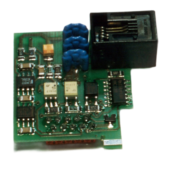
2. SETUP AND CONNECTIONS 2.1. INSTALLATION Lift out the electronics assembly from the case and use a screwdriver to pull on the junctions between the case and the gray market area to detach it from the case. The so performed orifice will allow to RS2 output board connector be brought out at the rear of the instrument. -
Page 8: Connection
2.2. CONNECTIONS Each output card is supplied with an adhesive label that indicates the wiring connections of each option (see Fig.1). to help identifying each terminal, this label should be placed in the lower side of the meter case, beside the basic functions label as shown in Fig. - Page 9 CONNECTIONS SCHEMATIC PC, PCL or similar communications Port shall not be connected to the telephone system. The display value can be requested through a push button on RTS line. If this push button is held closed the display value is continuously To be connected transmitted at 1 only if wish to...
- Page 10 RS232C PROGRAMMING OUTPUT MODELS BETA- M, BETA-D AND KAPPA- M...
-
Page 11: Programming Instructions
CONFIGURATION DIAGRAM OF RS232C FOR MODELS BETA-M, BETA-D, KAPPA-M ONLY BETA-M rS coN VERSION B-B ENTER - SoFt - 52 - bAud - 53 - AdrS - 54 - trAnS - ENTER ENTER ENTER ENTER Prot 1 Prot 2 Prot 3 1200 2400 4800... - Page 12 ACCESS TO THE SERIAL OUTPUT PROGRAMMING [13.1] Press the ENTER key to pass from the run mode to the programming mode (The -Pro- indication appears on the second display) and press repeatedly the key until the meter displays the indication given by figure13.1. Press ENTER to accede to the first programming menu, or...
- Page 13 MENU 52 TRANSMISSION RATE [14.1] The figure 14.1 shows the indication corresponding to the entry stage of the Baud rate configuration menu. Press ENTER to accede to this menu. If the programming of this parameter has been made and it is desired to pass to the following menu, press and go to figure 15.1.
- Page 14 [15.1] From the phase represented in figure 13.1, press key to accede to the ENTER menu selection level and to bring the meter to the entry stage of the address programming menu (see figure 15.1). Press the HOLD key, to get access to the programming of this parameter, or ENTER TARE key to go to the next menu.
- Page 15 MENU 54 VALIDATION OF COMMAND "Send Configuration" (only BETA- M version B- B) [16.1] From the phase represented in (Fig. 13.1), press ENTER key to access to the menu selection level and press three times key to bring the meter to the entry stage of the TRANS menu (auxiliary display shows (54 - trAnS).
- Page 16 RS2 OUTPUT OPTI ON PROGRAMMI NG FOR ALPHA S and GAMMA-M MODELS...
- Page 17 ALPHA AND GAMMA MODELS RS232C OUTPUT CONFIGURATION DIAGRAM PROG TARE HOLD LIMIT DATA INP1 DSP1 INP2 DSP2 STORE TARE RESET LIMIT MAX/MIN ENTER TEACH DATA ENTER PROG PROG TARE HOLD LIMIT DATA TARE HOLD LIMIT DATA INP1 DSP1 INP2 DSP2 STORE INP1 DSP1...
-
Page 18: Programming Instructions
4.1. PROGRAMMING INSTRUCTIONS The figure 19.1 represents the MODULE 5 for the serial output configuration, which is valid for models ALPHA-P, ALPHA-C, ALPHA-T, ALPHA-L, ALPHA-D and GAMMA-M. The module is composed of two menus of independent access that allow configuration of the following parameters : Menu 5A CnF : Configuration of the transmission rate and instrument s address. - Page 19 MENU 5A OUTPUT CONFIGURATION [20.1] The figure 20.1 represents the access to the output configuration menu (display 5 CnF, leds A and PROG activated), that allows to configure the PROG Baud rate and the instrument address number. Press key to accede ENTER this menu, or : to skip this menu and go to the next one.
- Page 20 MENU 5B - SELECTION OF THE COMMUNICATIONS PROTOCOLO [21.1] From the entry stage 5 (Fig. 20.1), press key to accede to ENTER programming menus and press twice key to bring the meter to the phase represented in figure 21.1 (5 trAnS indication, leds B and PROG PROG activated).
-
Page 21: Commands Table
Commands TABLE for KOSMOS type: ALPHA-C, ALPHA-P, ALPHA-T, ALPHA-L, ALPHA-D, BETA-M, BETA-D, GAMMA-M and KAPPA-M Command Instrument model Type Function function ØD Transmission display value Trans Transmission TARA value (offset in thermometers, Trans ØT preset in ALPHA-D) ØT Transmission Total value Trans ØP Transmission Peak value... - Page 22 Øz Reset 1 group of variables order Øn Reset setpoints latch order Øh Hold + reset 1 order Øx Reset batch counter order Transmission type of instrument Trans To use ModBus protocol, please consult specific manual MODBUS available on www.ditel.es...
- Page 23 All the DITEL products benefit from an unlimited and unconditional warranty of THREE (3) years from the date of their purchase. Now you can extend this period of warranty up to FIVE (5) years from the product commissioning, only by fulfilling a form.
- Page 24 DISEÑOS Y TECNOLOGIA, S.A. Polígono Industrial Les Guixeres C/ Xarol 8 C 08915 BADALONA-SPAIN Tel : +34 - 93 339 47 58 Fax : +34 - 93 490 31 45 E-mail : dtl@ditel.es www.ditel.es...
Need help?
Do you have a question about the Kosmos Series and is the answer not in the manual?
Questions and answers