
Subscribe to Our Youtube Channel
Related Manuals for IWAKI PUMPS SMX-F Series


Summary of Contents for IWAKI PUMPS SMX-F Series
- Page 1 IWAKI Self-priming Magnetic Drive Pump SMX-F Series (English) Instruction Manual Read this manual before use of product...
-
Page 2: Table Of Contents
Thank you for selecting an Iwaki SMX-F Series Self-priming Magnetic Drive Pump. This instruction manual deals with "Safety instructions", "Outline", "Installation", "Operation" and "Maintenance" sections. Please read through this manual carefully to ensure the optimum performance, safety and service of your pump. -
Page 3: Important Instructions
Important Instructions For the Safe and Correct Handling of the Pump ● "Safety Instruction" section deals with important details about handling of the product. Before the use of the pump, read this section carefully for the prevention of personnel injury or loss. ●... -
Page 4: Safety Instructions
Safety instructions WARNING ● Access limitation The magnet drive pump has a pair of strong magnets. A strong magnet field could adversely affect the persons who are assisted by electronic Prohibited devices such as the pacemaker. ● Turn off power before work Be sure to turn off the power before starting a maintenance/repair work. - Page 5 Safety instructions CAUTION ● Magnetic force affects magnetic disks/cards and wrist watches A pair of strong magnets is mounted in the pump and its magnet force may affect magnetic disks/cards or wrist watches. Do not bring them close to the pump. Prohibited ●...
- Page 6 Safety instructions CAUTION ● Do not lift the pump by gripping any plastic parts (pump unit, flange or base) The pump can drop unintentionally as a plastic part breaks, resulting in seri- ous injury. Use rope or chain to the motor to lift the motor horizontally. Prohibited ●...
-
Page 7: Outline
Outline 1. Unpacking & Inspection ......6 2. Product outline ........6 3. Model code ........... 7 4. Part names ........... 8 5. Overview ..........10 - 5 -... -
Page 8: Unpacking & Inspection
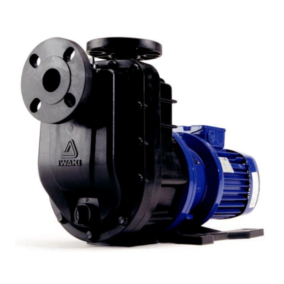
Frequency Manufacturing number 2. Product outline The SMX-F series pump is a self-priming centrifugal pump of a gas-liquid separation system. Fluoroplastic and fine ceramic wet ends are capable of handling a wide range of chemicals in vari- ous applications. Discharge ■... -
Page 9: Model Code
Outline 3. Model code SMX - F 22 0 CF V V C Series code SMX-F: CFRETFE type (Wet end material) Pump bore code (Inlet × Outlet bore) 22: 25A × 25A 44: 40A × 40A Motor output code 0: 0.4kW 1: 0.75kW 2: 1.5kW 3: 2.2kW... -
Page 10: Part Names
Outline 4. Part names □ SMX-F22 SMX-F220 MATERIAL PART NAMES Q'TY REMARKS FRONT CASE CFRETFE REAR CASE CFRETFE REAR CASING CFRETFE VOLUTE SPACER CFRETFE PLATE CFRETFE CFRETFE DRAIN CAP CFRETFE IMPELLER CFRETFE SMX-F220: FERRITE MAGNET + ALUMINIUM ALLOY DRIVE MAGNET UNIT SMX-F221: FERRITE MAGNET + DUCTILE IRON SMX-F222: REAR EARTH MAGNET + DUCTILE IRON SMX-F220, 221: FERRITE MAGNET + CFRETFE... - Page 11 Outline □ SMX-F44 SMX-F441 MATERIAL PART NAMES Q'TY REMARKS FRONT CASE CFRETFE REAR CASE CFRETFE REAR CASING CFRETFE VOLUTE SPACER CFRETFE PLATE CFRETFE CFRETFE DRAIN CAP CFRETFE IMPELLER CFRETFE SMX-F441: FERRITE MAGNET + DUCTILE IRON DRIVE MAGNET UNIT SMX-F442, 443: REAR EARTH MAGNET + DUCTILE IRON SMX-F441: FERRITE MAGNET + CFRETFE MAGNET CAPSULE SMX-F442, 443: REAR EARTH MAGNET + CFRETFE...
-
Page 12: Overview
Outline 5. Overview Motor nameplate Pump unit Use the power voltage specified Prime the pump through the prim- on the nameplate. ing port before operation. (Follow an applicable local power regulation.) "Arrow" label Discharge port The arrow indicates a rotational Priming port direction of the motor. -
Page 13: Installation
Installation 1. Before installation ....... 12 2. Installation location ......12 3. Installation ........... 13 4. Pipework ..........14 5. Wiring ..........17 - 11 -... -
Page 14: Before Installation
Installation 1. Before installation Precautions for electrical wiring and pipework CAUTION ● Do not drop the pump Do not drop, hit or drag the pump during carrying in or installation. Caution ● Ventilation Poisoning may result when handling an odorous/harmful liquid. Keep good ventilation in your operating site. -
Page 15: Installation
Installation 3. Installation Check if installation doesn't adversely affect facility, surrounding equipment and the pump. Install the pump according to the following instructions to ensure the optimum performance, safety and service. ■ Installation location • Keep a wide working space for convenience in installation and maintenance. •... -
Page 16: Pipework
Installation 4. Pipework Foreign matters such as sand and scale may enter pipework while you are working. They may cause fatal damage to the pump. Be sure to blow them out before operation. Also, do not apply adhesive too much or leave a screw or nut. If pipework directory weigh on the pump, plastic parts may be deformed. - Page 17 Installation 6. Do not make an arched line in order to prevent air from being trapped. A suction line right before the pump inlet should be laid on a rising gradient of 1/100 toward the pump. ■ Discharge line 1. Discharge pipe bore is related to pipe resistance Pipe resistance increases if a discharge pipe bore is too narrow, so that an intended flow can not be obtained.
- Page 18 Installation ■ Tightening torque between the pump and pipework • Flush the inside of pipes before connection. • Connect the pump to pipework via inlet and outlet flanges according to the table below. (This table is based on use of metal pipe flanges with rubber gaskets.) Bolt size Tightening torque (N•m) •...
-
Page 19: Wiring
Installation 5. Wiring 1. Electrical wiring and any work on power source must be performed by qualified persons only. We are not responsible for any injury and damage due to noncompliance with this notice. Contact us as necessary. 2. Install an electromagnetic switch according to motor specifications (voltage, capacity, etc.). 3. -
Page 20: Operation
Operation 1. Operational precautions ...... 19 2. Before operation ......... 20 3. Preparation ......... 22 4. Operation ..........23 - 18 -... -
Page 21: Operational Precautions
Operation 1. Operational precautions CAUTION ● Never run the pump dry or shut off a suction valve during operation. This may damage internal parts. Prohibit ● Stop the pump immediately when it is running under cavitation* . An abnor- mal sound of water flowing through a pipe or a significant pressure change (see a pressure gauge) is a sign of cavitation. -
Page 22: Before Operation
Operation WARNING ● Do not remodel the pump A remodelled pump will not be warranted. Also, we are not responsible for a Prohibit personal injury or property damage due to any modification. CAUTION ● Be sure to prime the pump before operation Always prime the pump when the pump is empty, for example, the pump is used for the first time or after dismantlement/assembly. - Page 23 Operation 3. ON-OFF operation Frequent ON-OFF operation damages the pump, especially in self-priming operation. Do not make ON- OFF operation more than six times per hour. 4. Handled liquid - Observe the next points 1. Slurry :Slurry can not be handled. 2.
-
Page 24: Preparation
Operation 3. Preparation ■ Preparations for operation 1. Check the pump and pipework before operation. a. Check there are no foreign matters in the supply tank and pipework. If foreign matters are stuck in suc- tion line, the pump may break. Do not leave any waste of bond, sealing materials and screws/nuts. b. -
Page 25: Operation
Operation 4. Operation ■ Starting process Operate the pump by the following procedure. Operation Procedure Remarks • • Close or open valves. Open suction valves fully. • Close a discharge valve fully (in flooded suction system). • Open discharge valves fully (other than flooded suction system). •... - Page 26 Operation Remarks Operation Procedure • < Points to be checked> Use a flow meter to see if the pump runs at a specified point. Check a flow meter and con- • If a flow meter is not available, check a specified point from discharge pres- firm that pump operation is sure, suction pressure and current value, taking account of pipe resistance.
- Page 27 Maintenance 1. Troubleshooting ........26 2. Maintenance & Inspection ....27 3. Spare & Wear parts ......31 4. Disassembly & Assembly ....33 - 25 -...
-
Page 28: Maintenance 1. Troubleshooting
Maintenance 1. Troubleshooting If you can not find out the root cause of failure, contact us. Trouble Cause Troubleshooting ● Priming liquid level is too low. ○ Stop the pump and feed a sufficient amount of ● The pump is running dry. priming liquid. -
Page 29: Maintenance & Inspection
Maintenance Trouble Causes Troubleshooting ● Voltage has dropped greatly. ○ Check voltage and frequency. ● Overload ○ Check that specific gravity and viscosity are The motor is overheated. suitable. ● Ambient temperature is too high. ○ Keep ventilation around the motor. The discharge rate has ●... - Page 30 Maintenance ► Mark each wire so that the wires can be connected correctly to the motor. ► Do not disassemble the pump beyond the extent shown on this manual. ► Make sure to close suction and discharge valves before dismantling/assembling the pump. Clean the inside of the pump as well.
- Page 31 Maintenance ■ Periodic inspection To ensure efficient and smooth operation, perform periodic inspection. Be careful not to damage internal sliding parts and plastic parts when dismantling the pump. • Inspect the pump every six months, logging inspection records. • For 24-hour continuous operation, inspect the pump every two months. •...
- Page 32 Maintenance ■ Wear limit of the bearing and spindle Check wear degree of the bearing and spindle. Rear casing Rear thrust ring (RF type) Mouth ring Impeller Impeller unit Bearing Rear thrust Magnet capsule Rear casing Magnet capsule Spindle Model SMX-F22,44 Dia.
-
Page 33: Spare & Wear Parts
Maintenance 3. Spare & Wear parts Appropriate spare parts are necessary for a long period of continuous operation. We recommend that wear parts be always in stock. Place an order for spares with the following information. 1. Part names and part number (See page 8 & 9 "4. Part names".) 2. - Page 34 Maintenance (SMX-F44) Part code Part names Material SMX-F441 SMX-F442 SMX-F443 Front case CFRETFE SMF0072 Rear case (for CF•RF) CFRETFE SMF0073 Rear case (for KK) CFRETFE SMF0074 Rear casing CFRETFE SMF0006 CFRETFE SMF0075 Volute spacer Impeller code CFRETFE SMF0076 CFRETFE SMF0092 Plate CFRETFE SMF0077...
-
Page 35: Disassembly & Assembly
Maintenance 4. Disassembly & Assembly See this exploded view when dismantling/assembling the pump. Do not dismantle the pump beyond the extent of instructions in this manual. Motor shaft Motor bracket Drive magnet unit Motor Hex. socket set screw Hex head bolt Drive magnet Spring washer Hex. - Page 36 Maintenance ■ Dismantlement 1. Remove the drain cap and drain liquid from the pump unit. (Liquid can not be drained completely. Some liquid remains in the pump head.) NOTE: Do not open the drain cap fully at once. Otherwise liquid may blow out. Front case CAUTION Wear chemical proof gloves for the pre-...
- Page 37 Maintenance 3. Remove three hex. socket head bolts which are fixing the rear casing support to rear case. Rear casing support Rear case Rear casing 4. Remove all cover caps by using nippers and loose the five nuts on the front case (pointed by arrows).
- Page 38 Maintenance 8. Immerse the rear casing in hot water for five minutes in order to soften it. And then remove a Rear casing spindle and a rear thrust. Rear thrust * A rear thrust ring is attached only to the RF *Rear thrust ring type.
- Page 39 Maintenance ■ Assembly INSPECTION If foreign matters such as iron powder stay on the magnet capsule by magnetic force, remove them. CAUTION Check that the O ring and gasket grooves are free from dust and scratches. Use new parts as necessary. 1.
- Page 40 Maintenance 5. Combine the front and rear cases and temporary Rear case Hex socket tighten them by the hex. socket head bolts for head bolt Plate preventing O ring and plate from moving. Front case Gasket Spring washer Plain washer Plain washer Cover cap 6.
- Page 41 Maintenance 9. Fit the rear casing support while holding the rear casing on the rear case. Temporarily tighten three hex. socket head bolts on the rear casing support and five stud bolts. Front case Fit rear casing support while Rear casing holding rear support casing.
- Page 42 Maintenance ■ Impeller unit removal Magnet capsule unit 1. Immerse and warm the combination of the impeller and magnet capsule units in hot water of Tap the impeller back. 90°C for five minutes. 2. Tap the back side of the impeller by a plastic Impeller unit hammer to detach it.
- Page 43 TEL : (1)508 429 1440 FAX : 508 429 1386 Germany : IWAKI EUROPE GmbH TEL : (49)2154 9254 0 FAX : 2154 1028 Australia : IWAKI Pumps Australia Pty. Ltd. TEL : (61)2 9899 2411 FAX : 2 9899 2421 Italy : IWAKI Italia S.R.L.
Need help?
Do you have a question about the SMX-F Series and is the answer not in the manual?
Questions and answers