
Related Manuals for Feig Electronic ID ISC.LRM1002-E


Summary of Contents for Feig Electronic ID ISC.LRM1002-E
- Page 1 IDENTIFICATION === Ende der Liste für T extm arke Deckbl att === INTEGRATION ID ISC.LRM1002-E Long Range Reader Modul M21110-5e-ID-B...
- Page 2 Composition of the information in this document has been done to the best of our knowledge. FEIG ELECTRONIC GmbH does not guarantee the correctness and completeness of the details given in this manual and may not be held liable for damages ensuing from incorrect or incomplete information. Since, despite all our efforts, errors may not be completely avoided, we are always grateful for your useful tips.
-
Page 3: Table Of Contents
Radio Approvals Declaration of Conformity (CE), (UKCA), (USA), (Canada) ........... 22 USA (FCC) and Canada (IC) .................... 23 5.2.1 Label Information Reader Modul ID ISC.LRM1002-E ........... 24 5.2.2 USA (FCC) and Canada (IC) approved antennas ..........24 Technical Data === Ende der Liste für T extm arke Note ===... - Page 4 IDENTIFICATION ID ISC.LRM1002-E 1 Safety Instructions ► The device may only be used for the intended purpose designed by for the manufacturer. ► The operation manual should be conveniently kept available at all times for each user. ► Unauthorized changes and the use of spare parts and additional devices which have not been sold or recommended by the manufacturer may cause fire, electric shocks or injuries.
-
Page 5: Performance Features Of Reader Family Id Isc.lrm1002
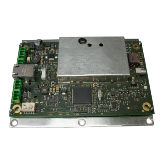
IDENTIFICATION ID ISC.LRM1002-E 2 Performance Features of Reader Family ID ISC.LRM1002 2.1 Performance Features The Reader has been developed for reading passive data carriers, so-called „Smart Labels“, using an operating frequency of 13.56 MHz. For the operation it is necessary to connect a appropriate external antenna to the connector ANT1. -
Page 6: Installation And Mounting
ø 4,5 mm ø 4,5 mm IN + IN - ANT1 V3 V2 V1 ø 4,5 mm* ø 4,5 mm* ø 4,5 mm* Figure 1: Scale drawing oft the Reader module ID ISC.LRM1002-E with mounting plate Page 6 of 26... -
Page 7: Terminals
IDENTIFICATION ID ISC.LRM1002-E To fully exploit the performance of the Reader Module, the heat sink should have a thermal resistance R of max. 2 K/W. When attaching the Reader Module to the heat sink you should strive for a little heat transfer resistance between the base plate and the heat sink as possible. The use of heat sink compound is recommended. -
Page 8: Antenna Connection
IDENTIFICATION ID ISC.LRM1002-E 3.2.1 Antenna connection The SMA socket „ANT1“ is located on the circuit board for connecting the antenna to the ID ISC.LRM1002. A external LED can also be supplied with 6,5 V through the antenna terminal. This can be controlled by software. The maximum current draw is then not allowed to exceed 20mA. - Page 9 IDENTIFICATION ID ISC.LRM1002-E Connection of a ID ISC.DAT (Dynamic Antenna Tuning Board) The maximum tightening torque for the SMA socket is 0.45 Nm (4.0 lbf in). Attention: Exceeding the tightening torque will destroy the socket. Terminal Description ANT1 For connecting the antenna (Input Impedance 50)
- Page 10 IDENTIFICATION ID ISC.LRM1002-E 3.2.1.1 Connection of a ID ISC.DAT (Dynamic Antenna Tuning Board) For tuning a ID ISC.DAT tuning board a DC voltage is required. This DC voltage must be provided via a power splitter (ID ISC.ANT.PS-B) or a antenna multiplexer (ID ISC.ANT.MUX) Figure 4 shows the DC supply of the ID ISC.DAT with a power splitter.
-
Page 11: Supply Voltage
IDENTIFICATION ID ISC.LRM1002-E 3.2.2 Supply voltage The reader has to be supplied by a limited power supply according EN 62368-1 Chapter Q.1, or with a NEC Class 2/LPS certified power supply. The external wiring for the power supply must be compliant with - IEC 60332-2-1 and IEC 60332-2-2 for Wire Cross Section <... -
Page 12: Optocouplerinputs (X5 / In1)
IDENTIFICATION ID ISC.LRM1002-E 3.2.3 OptocouplerInputs (X5 / IN1) The optocoupler input is available on Terminal X5. IN + IN - Figure 7: Optocoupler pin-outs on terminal X5 The optocoupler on terminal strips X5 is galvanically isolated from the Reader electronics and must therefore be powered externally. - Page 13 IDENTIFICATION ID ISC.LRM1002-E Output 24V (X5 / VIN, GND) Figure 8: External power supply for the optocouplers Figure 9: Possible internal power supply for the optocouplers The input LED for the optocoupler is internally connected to a series resistor of 3,74k and is limited to an input current of max.
- Page 14 IDENTIFICATION ID ISC.LRM1002-E Page 14 of 26...
-
Page 15: Relay (X6 / Rel1)
IDENTIFICATION ID ISC.LRM1002-E 3.2.4 Relay (X6 / REL1) The relay output has a changeover contact. These outputs, which are located on terminals X6, is galvanically isolated from the Reader electronics and must therefore be externally supplied. The external voltage may however be provided by the reader from connector X5 VIN and GND. - Page 16 IDENTIFICATION ID ISC.LRM1002-E Output 24V (X5 / VIN, GND) Figure 10: Relay Outputs on terminal X6 Figure 11: External wiring of the relay output’s with external voltage Notes: • The relay output is configured for max. 24 V / 1 A.
-
Page 17: Output 24V (X5 / Vin, Gnd)
IDENTIFICATION ID ISC.LRM1002-E 3.2.5 Output 24V (X5 / V , GND) The output V /GND can be used to power the optional external circuitry of the digital inputs or relay. The maximum current consumption must not exceed 1A. IN +... -
Page 18: Interfaces
IDENTIFICATION ID ISC.LRM1002-E 3.3 Interfaces 3.3.1 RS232-Interface X4 The RS232 interface is connected on X4. The transmission parameters can be configured by means of software protocol. Figure 13: RS232 interface pin-outs on X4 Kurzzeichen Description RS232 – (Transmit) RS232 – (Receive) RS232 –... -
Page 19: Usb - Interface X11 (Host Communication)
IDENTIFICATION ID ISC.LRM1002-E 3.3.2 USB – Interface X11 (Host Communication) The USB socket on the board is terminal X11. The data rate is reduced to 12 Mbit (USB full speed). A standard USB-cable can be used. Figure 15: USB-Interface for host communication The Figure 16 and table shows the connection of connector X11 (5pol.) type “JST PH”... -
Page 20: Ethernet-Interface On X3 (10/100 Base-T)
IDENTIFICATION ID ISC.LRM1002-E 3.3.3 Ethernet-Interface on X3 (10/100 Base-T) The Reader has an integrated 10 / 100 Base-T network port for an RJ-45. Connection is made on X3 and has an automatic “Crossover Detection” according to the 1000 Base-T Standard. -
Page 21: Operating And Display Elements
IDENTIFICATION ID ISC.LRM1002-E 4 Operating and Display Elements 4.1 LEDs Abbreviation Description LED V1 (green) "RUN-LED 1" Indicates proper running of the internal Reader software (DSP) Comes on during Reader initialization after power-on or after a reset. LED V2 (blue) -
Page 22: Radio Approvals
5.1 Declaration of Conformity (CE), (UKCA), (USA), (Canada) Declaration of Conformity (CE) Hereby, FEIG ELECTRONIC GmbH declares that the radio equipment type ID ISC.LRM1002-Eis in compliance with Directive 2014/53/EU. The full text of the EU declaration of conformity is available at the following internet address: https://www.feig.de/en/service/eu-declarations-of-conformity/... -
Page 23: Usa (Fcc) And Canada (Ic)
Warning: Changes or modification made to this equipment not expressly approved by FEIG ELECTRONIC GmbH may void the FCC authorization to operate this equipment. Installation with FCC / IC Approval:... -
Page 24: Label Information Reader Modul Id Isc.lrm1002-E
IDENTIFICATION ID ISC.LRM1002-E 5.2.1 Label Information Reader Modul ID ISC.LRM1002-E The following information has to be mount outside on the housing of the reader. 5.2.2 USA (FCC) and Canada (IC) approved antennas This radio transmitter (identify the device by certification number, or model number if Category II) has been approved by Industry Canada to operate with the antenna types listed below with maximum permission gain and required antenna impedance for each antenna type indicated. -
Page 25: Technical Data
IDENTIFICATION ID ISC.LRM1002-E 6 Technical Data Mechanical Data 0,35 kg Weight 160 mm x 120 mm x 35 mm Dimensions (6.29 inch x 4.72 inch x 1,38 inch) (W x H x D) Electrical Data 15 % Power supply 24 V Max.16 VA... - Page 26 IDENTIFICATION ID ISC.LRM1002-E Applicable Standards RF Approval EN 300 330 Europe EN 300 330 FCC 47 CFR Part 15 RSS-210 Canada EN 301 489 Safety Low Voltage Directive EN 62368-1 EN 50364 Human Exposure Page 26 of 26...
Need help?
Do you have a question about the ID ISC.LRM1002-E and is the answer not in the manual?
Questions and answers