Ampac SmartTerminal Installation, Comissioning & Operation
Hide thumbs
Also See for SmartTerminal:
- Installation, commissioning & operation (20 pages) ,
- Installation, commissioning & operation (22 pages)
Table of Contents
Advertisement
Quick Links
WORLD LEADER OF INNOVATIVE SOLUTIONS IN FIRE DETECTION AND ALARM SYSTEMS
Installation Commissioning & Operation
"Our aim is to provide
'Consistently Excellent Service'
SmartTerminal
S
S
S
in the eyes of our customers"
MAN2961-6
m
a
r
t
T
e
r
m
m
a
r
t
T
e
r
m
m
a
r
t
T
e
r
m
A
S
4
4
2
8
A
S
4
4
2
8
A
S
4
4
2
8
i
n
a
l
i
n
a
l
i
n
a
l
Advertisement
Table of Contents

Related Manuals for Ampac SmartTerminal


Summary of Contents for Ampac SmartTerminal
- Page 1 WORLD LEADER OF INNOVATIVE SOLUTIONS IN FIRE DETECTION AND ALARM SYSTEMS SmartTerminal Installation Commissioning & Operation “Our aim is to provide ‘Consistently Excellent Service’ in the eyes of our customers” MAN2961-6...
-
Page 3: Table Of Contents
FACP Communications Extender Board Interconnection..........10 Setting the Address...................... 10 Setting the SmartTerminal in ConfigManager.............. 11 5.4.1 Setting the SmartTerminal Reporting Parameters ........11 SmartTerminal Controls and Indicators ..............13 LCD Screen Format ..................... 17 Trouble Shooting Chart....................19 Page 3... -
Page 4: Introduction
FACP. Operation The operation of SmartTerminal can be considered to be in one of three states, these are; 1. Power up - when the SmartTerminal is initialising 2. Normal - when the SmartTerminal address has been set and is communicating with the... -
Page 5: Specifications
RS485 communications and 27VDC supply to the LCD Board 3. BRD82ICC2 – Control, LCD Communications and LCD Driver Board Note: A maximum of 30 SmartTerminal’s may be connected to the communications bus over a distance of approximately 1.2Kms Page 5... -
Page 6: Operational & Key Features
4 line by 40 character LCD with backlight and navigation keys keys allow the SmartTerminal to be used for FACP operation and interrogation. Note the backlight is only energised when alarms are present, a key has been pressed or controls enable key switch is enabled ... -
Page 7: Fixing The Chassis To The Wall
SmartTerminal Installation Commissioning & Operation 4.1.2 Fixing the Chassis to the Wall Taking into account the weight of the panel securely mount it by using the three keyhole mounting holes in the backpan, two in the top and one in the bottom. Use suitably sized screws and plugs for the type of mounting surface. - Page 8 SmartTerminal Installation Commissioning & Operation CONTROL KEY SUPPLIED PANEL CLIPS TAPED TO TOP INTO FRONT DOOR OF ENCLOSURE TAP AROUND RIM TO REMOVE KNOCKOUTS CAB2116 BRD82LTB INSERT KEY TABS HERE TO REMOVE TO UNLOCK FRONT DOOR ENCLOSURE PUSH UP HERE TO SLIDE...
-
Page 9: Installation & Cabling
DOOR SW DBA /MCP + IN - + BAT - TO BATTERIES Figure 5: FACP Internal Layout The SmartTerminal is then connected to the FACP as shown below. SHIELDED COMMS CABLE FACP FRONT PANEL CONTROL (BRD85CTLA) +24VDC RJ45 CN17 CH16... -
Page 10: Smartterminal Termination Board Interconnection
Use the “PREVIOUS (A-) and NEXT” (A+) keys to select the desired address. The default value for this address is 255 which is not a valid SmartTerminal address. The user must then select an address value from 1 to 30, i.e. the same address as that set in the FACP. The keys corresponding to C- (ACK) and C+ (RESET) are used in a similar manner to decrease and increase the LCD contrast level. -
Page 11: Setting The Smartterminal In Configmanager
Figure 7 The Controller Edit / Add Module Types Screens Click within the check box to “tick” the check box and click OK. Double click on the Controller to open the Panel screen and the SmartTerminal tab should now be visible along with the other installed functions. 5.4.1... - Page 12 SmartTerminal Installation Commissioning & Operation In the above example Card 1 & 2; Are active Are situated in the factory floor area 8 Will display all Alarms Will not display any Faults, and Will not display any Disables Card 3 ...
-
Page 13: Smartterminal Controls And Indicators
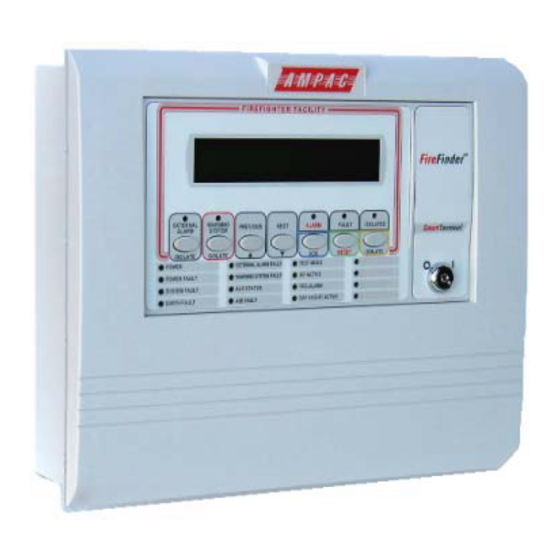
SmartTerminal Installation Commissioning & Operation SmartTerminal Controls and Indicators All controls, except for the Enable / Disable keyswitch, are of a momentary push button style. Figure 10 SmartTerminal Front Panel Layout EXTERNAL BELL ISOLATE (Yellow) Illuminated when the External Bell output has been isolated either at the SmartTerminal or the FACP. - Page 14 PREVIOUS Primary Function Press to display the previously displayed LCD screen Secondary Function Set SmartTerminal address – A – (minus) decrement number Active at access level 1 and 2 NEXT Primary Function Press to display the next displayed LCD entry Secondary Function Set SmartTerminal address –...
- Page 15 Controls enable key switch. The SmartTerminal by default is in access level 1, and when the control enable key switch is in the ENABLED position, the SmartTerminal is in access level 2. Access level 2 is used to restrict access to certain controls.
- Page 16 SmartTerminal Installation Commissioning & Operation POWER FAULT (Yellow) Illuminated when there is a fault with the power supply. Fault can be no mains, high charger voltage, low battery voltage or missing/damaged battery SYSTEM FAULT (Yellow) Illuminated when the FACP is unable to provide mandatory functions.
-
Page 17: Lcd Screen Format
Fault sequence number ( Device Fault nnn of nnn) Note: The fault types only relate to devices. In the event of a loss of communications, for a period of greater than 15 seconds the SmartTerminal will default to the No Communications screen. The format for this screen is:... - Page 18 A - A + C - C+ A - A + : adjusts the address 1 to 30, 30 being the maximum number of SmartTerminal’s that can be connected to the FACP, ( default is 255 which is not a valid address).
-
Page 19: Trouble Shooting Chart
Refer FACP LCD. This may identify where there is a break working in the communication line Check the SmartTerminal Diagnostic Config LED is flashing. If not the FACP is not communicating with the SmartTerminal. Check the RS485 cabling. If flashing check the SmartTerminal’s address. - Page 20 Fax: +44 (0) 1302 835 021 Fax: 64 9 443 8073 Email: info@ampac.net Email: info.eu@ampac.net Email: info.nz@ampac.net Assessed to ISO9001 LPCB ref. no 952 (AMPAC Europe) (HEAD OFFICE) UNCONTROLLED DOCUMENT NOTE: Due to Ampac’s commitment to continuous improvement specifications may change without notice. Page 20...
Need help?
Do you have a question about the SmartTerminal and is the answer not in the manual?
Questions and answers