
Related Manuals for Kangaroo Aussie II K8605


Summary of Contents for Kangaroo Aussie II K8605
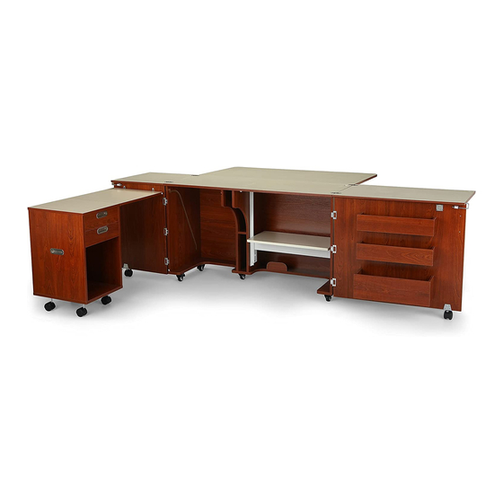
- Page 1 ASSEMBLY INSTRUCTIONS A u s s i e I I ITEM NO.: K8605 Teak K8611 Ash White SEW IN COMFORT. SEW LONGER.™...
- Page 2 General A ssembly Guidelines Read the instructions carefully before beginning the assembly process to ensure proper assembly of this product. Please open and inspect the contents of box(es) to see that all parts and hardware are included. 2. Tools Required Phillips Screwdriver Hammer Electric Screwdriver...
-
Page 3: Item Description
Parts List: Panels ITEM DESCRIPTION ITEM DESCRIPTION PACK. PACK. 3 of 5 Hardware & Caddy Panels* Door Bin Front 1 of 5 3 of 5 Door Bin Side Quilt Extension Panel 2 of 5 3 of 5 Back Panel Door Bin Bottom 2 of 5 Left Side Panel Large Bin Front... - Page 4 Par ts List TIP: Keep all the parts in their individually labeled bags. This will make finding parts easier as you assemble your cabinet. The hardware counts below DO NOT include hardware for the Caddy. If you would like to begin by building the Caddy, please turn to Page 23 of this manual.
- Page 5 Par t 1: Main Cabinet We can’t wait to get your brand new Aussie II Sewing Cabinet up and running! Please contact our Customer Service Team at 1-800-533-7347, ext. 1 during normal business hours with any assembly related questions. Begin by unpacking Box 1. You will find all of the hardware necessary for this assembly project, along with panels for the construction of the Caddy.
- Page 6 Main Cabinet Step 1: Base Plate Caster x5 8x16 Fix Bolt x20 Allen Wrench x1 Attach 5 Plate Casters to the underside of Panel G with 20 Fix Bolts (four bolts for each caster). Tighten with provided Allen Wrench. Lock the Casters and flip Panel G over for the next step 8x30 Dowel Pin x2 ⁄...
- Page 7 Main Cabinet Step 2: Back and Side Panels 8x30 Dowel Pin x8 Insert Dowel Pins into sides of Panel D 8x30 Dowel Pin x8 6x35 Cam Bolt Install 2 Cam Bolts in Panel X Install 2 Cam Bolts in Panel Z Insert 4 Dowel Pins in Panel X Insert 4 Dowel Pins in Panel Z Aussie II...
- Page 8 Main Cabinet Step 2: Back and Side Panels 3.5x14 Screw Lift Rail (Right) x1 Attach Lift Rail (right) to Panel Z with s1 Screws. NOTE: The illustration below shows upside down assembly of Panels D, X and Z. Assembling these panels upside down will make attaching Panel G easier. Note that Panel D must have Cam Locks facing the back of the cabinet.
- Page 9 Main Cabinet Step 2: Back and Side Panels ⁄ “ Cam Cover Attach Panel G as shown. Tighten Cam Locks and cover with Cam Covers. Make sure Casters are locked and flip the cabinet over. You may need a friend to help you, but it is not required. Aussie II Assembly Instructions...
- Page 10 Main Cabinet Step 3: Center Panels 8x30 Dowel Pin x12 Insert Dowel Pins into the edges of Panels Y1, Y2 and F Aussie II Assembly Instructions...
- Page 11 Main Cabinet Step 3: Center Panels 3.5x14 Screw Lift Rail (Left) x1 Attach Lift Rail (Left) to Panel Y2 with s1 Screws Slide Dowel Pins on Panel F into Panels Y1 and Y2 as shown. Aussie II Assembly Instructions...
- Page 12 Main Cabinet Step 3: Center Panels ⁄ “ Cam Cover Lower Panels Y1 and Y2 onto Cam Bolts on Panel G. Tighten Cam Locks and apply Cam Covers over tightened Cams. LIFT INSTALLATION WARNING: DO NOT remove the small wooden block from the Lift until assembly is complete. If the block is removed or falls out before lift assembly is complete, the cables will retract, making installation difficult.
- Page 13 Main Cabinet Step 4: Lift Panel 3.5x14 Screw Attach the Lift to Panel A4 using s1 Screws. Guide Lift onto Lift Rails using plastic guides. Insert ends of cable into rail tabs; make sure the cable is hooked into the rail tabs on both sides.
- Page 14 Main Cabinet Step 4: Lift Panel Cable Lift rail Rail tabs Plastic guides on Lift Lift rail REMINDER: Our Customer Service Team is available for any assembly related questions. Please call 1-800-533-7347, ext. 1 to speak with an Assembly Expert. Aussie II Assembly Instructions...
- Page 15 Main Cabinet Step 5: Top and Quilt Panel 6x35 Cam Bolt Lock Plate 3.5x14 Screw Insert Cam Bolts into Panel A. Attach Lock Plate to Panel A using s1 Screws, making sure that the flat face of the Lock Plate faces toward the front edge of Panel A. Lower Panel A onto Panels X, D, Y1, Y2 and Z.
- Page 16 Main Cabinet Step 5: Top and Quilt Panel 3.5x14 Screw 14mm Wrench x1 Butt Hinge x2 Caster x1 3x14 Screw Alignment Pin Magnet x1 Attach Magnet Catch Plate m to Panel O1 using s2 Screws. Install Alignment Pin s5 and screw in. Install Butt Hinges h1 using s1 Screws Insert Caster t1 into Caster Bracket and tighten with Wrench r3...
- Page 17 Main Cabinet Step 5: Top and Quilt Panel Magnet x1 Flap Hinge x3 3.5x14 Screw Attach Magnet and Flap Hinges to Panel A1 with S1 Screws as shown. 3.5x14 Screw Balance Panel A1 on the gateleg, Panel O1. Using S1 Screws, attach Flap Hinges to Panel D from underneath as shown.
- Page 18 Main Cabinet Step 6: Cabinet Doors 3x14 Screw Door Plate x2 Handle x1 Allen Wrench x1 Flush Hinge x3 4x20 Fix Bolt x2 Caster x1 Door Hook x1 Install Flush Hinges and Door Plates with S2 Screws. Note that the rounded part of the Door Plates will overhang the edge of the door.
- Page 19 Main Cabinet Step 6: Cabinet Doors Insert Cam Bolts on Panels L1 and K1 into Cam Locks on Panels L2 and K2 and tighten. NOTE: The Cam Locks on Panels L2 and K2 will be on the bottom of the bin. NOTE: You will complete assembly of L1/L2 Panels twice.
- Page 20 Main Cabinet Step 6: Cabinet Doors 4x20 Fix Bolt x2 3x20 Screw 6x25 Cam Bolt Caster x1 Door Hook x1 14mm Wrench x1 3x14 Screw Flush Hinge x3 Handle x1 Lock 1. As shown in the left corner of the illustration, screw Caster into caster bracket and tighten with included 14mm Wrench.
- Page 21 Main Cabinet Step 6: Cabinet Doors ⁄ “ Cam Cover Insert Cam Bolts on Panel V2 into Cams on assembled Bins. Tighten and cover with Cam Covers. TIP: Start with the top bin and work your way down. This will make it easier to reach the Cam Locks on the bottoms of the bins.
- Page 22 Main Cabinet Step 6: Cabinet Doors 3x14 Screw Add door V1 to side Panel X by attaching Flush Hinges using S2 Screws. Add door V2 to side Panel Z by attaching Flush Hinges using S2 Screws. NOTE: You may need a friend to help you hold the door steady as you attach it, but it is not required.
- Page 23 Par t 2: Caddy Aussie II Assembly Instructions...
- Page 24 Caddy Panel and Hardware List 6x35 Cam Bolt ⁄ “ 8x30 Dowel Pin x12 Cam Cover 3.5x35 Screw Allen Wrench x1 8x16 Fix Bolt x16 Plate Caster x4 Aussie II Assembly Instructions...
- Page 25 Caddy Step 1: Base 6x35 Cam Bolt Insert Cam Bolts into pre-installed Cam Bolt Anchors. Flip Panel G over to attach Casters. Allen Wrench x1 8x16 Fix Bolt x16 Attach Casters using Allen Wrench as illustrated below. Set Panel G aside. Plate Caster x4 Aussie II Assembly Instructions...
- Page 26 Caddy Step 1: Base 6x35 Cam Bolt 8x30 Dowel Pin x12 Insert Dowel Pins into the sides of Panel D. Insert Cam Bolts into the top of Panel Z Insert Dowel Pins into the sides of Panel Z Insert Cam Bolts into the top of Panel X Insert Dowel Pins into the sides of Panel X Aussie II Assembly Instructions...
- Page 27 Caddy Step 1: Base ⁄ “ Cam Cover Insert Cam Bolts on Panels X and Z into Panel D. Tighten Cam Locks and cover with Cam Covers Aussie II Assembly Instructions...
- Page 28 Caddy Step 1: Base ⁄ “ Cam Cover Attach Panel G as shown, making sure that the arrow on Panel G faces the back of the caddy. Tighten Cam Locks and cover with Cam Covers. Aussie II Assembly Instructions...
- Page 29 Caddy Step 2: Top 6x35 Cam Bolt Install Cam Bolts as illustrated below. ⁄ “ Cam Cover Lower Panel A/A1 onto Panels D, X and Z as shown. Tighten Cam Locks and apply Cam Covers. Aussie II Assembly Instructions...
- Page 30 Caddy Step 3: Drawers Remove the screws on both ends of side draw- er rails on Panels L1 and L2 to access pilot holes for drawer back. Connect drawer panels L1, L2 and L3 with s3 screws. Slide bottom Panel L4 into grooves on L, L1, L2 as illustrated.
- Page 31 Caddy Positioning Your caddy can be positioned in either of the configurations shown below. Be sure to always have the caddy attached to the cabinet to prevent tipping. Position 1: Nestle the caddy into the main cabinet with rollers in grooves Position 2: Anchor the Caddy to the left Main Cabinet door using pre-installed Panel...
-
Page 32: Limited Lifetime Warranty
Kangaroo Sewing Furniture is designed for residential use only. ARROW SHALL HAVE NO LIABILITY for ANY INCIDENTAL OR CONSEQUENTIAL DAMAGES OF ANY KIND and all such damages are EXCLUDED FROM THIS Warranty, such as loss of use, disassembly, transportation, labor, or damage to property on or near the product. - Page 33 Accessories to Complete Your Sewing Experience Custom Insert Arrow Sewing Chairs Enhance your sewing experience with a custom Arrow’s #1 Rated Height Adjustable Sewing Chair acrylic sewing insert! Custom acrylic sewing is a must have accessory for your dream sewing inserts are designed to fill the gap between your room! Cute, comfortable and convenient - our sewing machine and sewing cabinet’s lift opening...
Need help?
Do you have a question about the Aussie II K8605 and is the answer not in the manual?
Questions and answers