Advertisement
Quick Links
Advertisement

Subscribe to Our Youtube Channel
Related Manuals for Kangaroo Aussie II Series


Summary of Contents for Kangaroo Aussie II Series
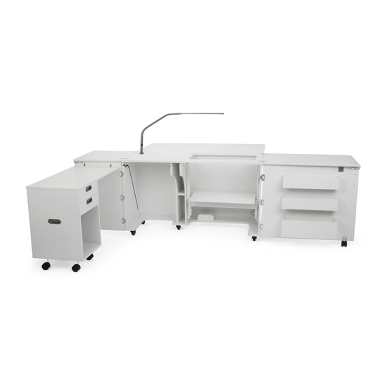
- Page 1 ASSEMBLY INSTRUCTIONS A u s s i e I I ITEM NO.: K8605 Teak K8611 White SEW IN COMFORT. SEW LONGER.™...
- Page 2 Read the instructions carefully before starting. Please open and inspect the contents of boxes to see that all parts are included. You will need a Phillips head and a flat head screwdriver. A power screwdriver or cordless drill is preferable. Ensure that the Phillips head fits neatly and fully engages the screw to avoid damage to the screws.
-
Page 3: Parts List
Par ts List ITEM DESCRIPTION QTY. PACK. ITEM DESCRIPTION QTY. PACK. Top Panel 1 of 4 Right Door Panel 3 of 4 Platform Cover 1 of 4 Left Partition Panel 3 of 4 Right Leaf 1 of 4 Right Partition Panel 3 of 4 Left Leaf 1 of 4... - Page 4 Par ts List ITEM DESCRIPTION QTY. ITEM DESCRIPTION QTY. 6x35 Cam Bolt Handle 6x25 Cam Bolt Door Hook ⁄ “ Cam Cover Butt hinge 8x30 Dowel Pin Flush Hinge Locking Plate Caster Flap Hinge Wrench 8x16 Fix Bolt 14mm Spanner 4x20 Fix Bolt 3.5x14 Screw Magnet, Catch Plate...
- Page 5 Step 1. Preparation Panels A, D, V2, Y1 and Y2. 1. Insert cam bolts c1 into panel A. 2. Fix lock plate using screws s1 to panel A as illustrated below. Orient the flat face of the lock plate L towards front edge 6x35 Cam Bolt of the panel A.
- Page 6 Step 2. Preparation Panels A1, O1, X, Z, V1, F, O, L, L1, K, K1. 1. Insert cam bolts c1 into panels X and Z. 6x35 Cam Bolt 2. Insert cam bolts c3 into panels K, K1, L and L1. 3.
- Page 7 Step 3. Fix Lifter Rail (right) to panel Z using screws s1 following predrilled holes as shown on the illustration below. Lifter Rail (Right) x1 3.5x14 Screw Step 4. Fix Lifter Rail (Left) to panel Y2 using screws s1 following predrilled holes as shown on the illustration below. Lifter Rail (Left) x1 3.5x14 Screw Rail faces front of panel.
- Page 8 Step 5. Panels D, X, Z assembly. Insert cam bolts c1 on panels X and Z into cams on panel D and tighten in a clockwise direction as illustrated below. Please note the orientation of panel D with the cams facing backwards. This is the correct orientation. Apply cam covers c2 over tightened cams.
- Page 9 Step 7. Panel G assembly. Insert cam bolts c1 on panel G into cams on panel O and tighten in a clockwise direction as illustrated below. Apply cam covers c2 over tightened cams. ⁄ “ Cam Cover 180° Step 8. Panel G assembly. Insert cam bolts c1 on panel G into cams on panels X, Z and D and tighten in a clockwise direction as illustrated below.
- Page 10 Step 9. Flip cabinet over (right side up). We recommend that two people do this step. Step 10. Panel F assembly. Insert Dowel Pin d1 on panel F into cams on panels Y1 and Y2. Aussie II Assembly Instructions...
- Page 11 Step 11. Panels Y1, Y2 and F assembly. 1. Lower Unit Y1-F-Y2 over cam bolts c1 on panel G tighten in a clockwise direction as illustrated below. 2. Apply cam covers c2 over tightened cams. ⁄ “ Cam Cover Step 12. Lifter Panel assembly. Fix lifter to panel A4 using screws s1 following predrilled holes as shown on the illustration below.
- Page 12 Step 13. Mounting the Lifter Assembly. 1. Position lifter onto side rails using plastic guides; make sure the cable is hooked into the rail tabs on both sides then lower the lift. See illustration below. 2. When lifter is pushed to first lock position remove a small wooden block that will be released from lifter. Plastic guides Cable Lifter rail...
- Page 13 Step 15. Panels L1, L2, K1 and K2 assembly. 1. Insert cam bolts c3 on panel L1 and K1 into cams on panels L2 and K2 and tighten in a clockwise direction as illustrated below. The cams on K2 and L2 should face down, not to the inside of the bin. 2.
- Page 14 Step 17. Panels V2, K and L assembly. 1. Insert cam bolts c3 on panel V2 into cams found on L1 and L2 assembled in Step 15 and K1 and K2 assembled in Step 16. 2. Tighten cams in clockwise direction attaching bins to Door V2. Apply cam covers c2 over tightened cams.
- Page 15 Step 19. Panel 01 assembly. Fix panel O1 butt hinges h1 onto panel D using screws s1 as illustrated below. 3.5x14 Screw Step 20. Panel A1 assembly. 1. Have a second person hold the A1 Quilt panel balanced on the gate leg panel O1. 3.5x14 Screw 2.
- Page 16 CADDY Par ts List ITEM DESCRIPTION QTY. PACK. Top Panel 4 of 4 Top Panel Leaf 4 of 4 Bottom Panel 4 of 4 Back Panel 4 of 4 Left Side Panel 4 of 4 Right Side Panel 4 of 4 Drawer Front 4 of 4 Drawer Side- Left...
- Page 17 Par ts List ITEM DESCRIPTION QTY. 6x35 Cam Bolt ⁄ “ Cam Cover 8x30 Dowel Pin Caster Caster Washer 3.5x35 Screw Butt hinge (Pre-installed) ⁄ “ 8x30 Dowel Pin x12 6x35 Cam Bolt Cam Cover 3.5x35 Screw Caster x4 Caster Washer x4 12mm Spanner x1 Pre-installed parts Drawer Runners...
- Page 18 Step 21. Preparation Panels X, Z, D, A, L. 1. Insert cam boltsc1 into panels A, G, L, X and Z as illustrated below. 2. Insert dowel pins d1 to panels X, D and Z as illustrated below. 6x35 Cam Bolt 8x30 Dowel Pin x12 Step 22.
- Page 19 Step 23. Panel G assembly 1. Place caster washer b4 on extension casters t3 and screw into anchors in bottom panel G. Caster x4 Caster Washer x4 12mm Spanner x1 Step 24. Panel A and G assembly. 1. Insert cam bolts c1 on bottom panel G into cams in panels X and Z. Tighten cams in clockwise direction. 2.
- Page 20 Step 24. Drawer assembly. 1. Slide bottom L4 into L, L1, L2 and L3 grooves as illustrated. 2. Connect drawer panels L1, L2 and L3 with screws s3 as illustrated below. 3.5x35 Screw 3. Insert cam bolts c3 on panel L into cams on panels L1 and L2 and tighten in a clockwise direction as illustrated below. ⁄...
- Page 21 Step 26. Caddy positioning 1. Position the caddy in front of the cabinet and carefully lift the flap. Place the pre-installed flap rollers into the groove and gently slide the caddy into the cabinets. Step 27. Caddy positioning 1. Make sure the door is open and secured to cabinet leaf with Door Hook and caster is locked. 2.
-
Page 22: Additional Limitations
Caster damage as a result of moving furniture fully loaded or with locked casters. Damage resulting from electrical surge or lightning. Use in commercial or education environments. Kangaroo Sewing Furniture is designed for residential use only. ARROW SHALL HAVE NO LIABILITY for ANY INCIDENTAL OR CONSEQUENTIAL DAMAGES OF ANY KIND and all such damages are EXCLUDED FROM THIS WARRANTY, such as loss of use, disassembly, transportation, labor or damage to property on or near the product. - Page 23 Arrow Sewing Chairs Enhance your sewing experience with a custom- Our adjustable height sewing chair is a perfect made insert for your Arrow or Kangaroo cabinet. accessory for any craft and sewing room. The Inserts are designed to reduce the gap between chair’s height is adjustable with easy to use...
Need help?
Do you have a question about the Aussie II Series and is the answer not in the manual?
Questions and answers