
Related Manuals for Kangaroo Wallaby II


Summary of Contents for Kangaroo Wallaby II
- Page 1 ASSEMBLY INSTRUCTIONS Wa l l a by I I ITEM NO.: K8405 Teak K8411 Ash White SEW IN COMFORT. SEW LONGER.™...
-
Page 2: General A Ssembly Guidelines
Cleaning – To remove marks and enhance the surface, wipe with a gentle all-purpose cleanser. DO NOT use ammonia-based, harsh chemicals or abrasive cleaning agents. Wipe dry immediately. Electrical and Hydraulic Lifts – Require annual lubrication with WD-40 or similar lubricant. Wallaby II Assembly Instructions... - Page 3 Door Bin Sides 1 of 4 Left Side Panel 1 of 4 Fixed Shelf On Door 1 of 4 Partition 1 of 4 Platform 1 of 4 Fixed Shelf 1 of 4 Lift & Rails 4 of 4 Wallaby II Assembly Instructions...
-
Page 4: Par Ts List: Hardware
Flush Hinge x6 Catch plate x1 Butt Hinge x2 Stay Arm x1 Caster x3 Locking Plate Caster x5 Pre-installed parts Lift x1 Drawer Runners Lift Rail Lift Rail (Left) x1 (Right) x1 Caster Bracket Snag Free Hinge Wallaby II Assembly Instructions... -
Page 5: Step 1: Cabinet Base
Step 1: Cabinet Base We can’t wait to get your brand new Wallaby II Sewing Cabinet up and running. Please contact our Customer Service Team at 1-800-533-7347, ext. 1 during normal business hours with any assembly related questions. 8x16 Fix Bolt x20... - Page 6 Insert 4 d1 Dowel Pins into the edges of Panel Z Insert 4 d1 Dowel Pins into the edges of Panel Y Install 2 c1 Cam Bolts into pre-installed Cam Install 2 c1 Cam Bolts into pre-installed Cam Anchors on Panel Z Anchors on Panel Y Wallaby II Assembly Instructions...
- Page 7 Lift Rail (Left) x1 Flip Panel Y over 3.5x14 Screw Attach Lift Rail (Left) to Panel Y with s1 Screws Lift Rail (Right) x1 Attach Lift Rail (Right) to Panel Z with s1 Screws 3.5x14 Screw Wallaby II Assembly Instructions...
- Page 8 Note: Cam Locks on Panel D will be facing the back of the cabinet. ⁄ “ Cam Cover Attach Panels X and Z to Panel D. Tighten Cam Locks and apply Cam Covers Attach Panel F to Panels X and Y. Tighten Cam Locks and apply Cam Covers Wallaby II Assembly Instructions...
-
Page 9: Step 3: Attaching The Base
Step 3: Attaching the Base ⁄ “ Cam Cover Attach Panel G to Panels X, D, Y and Z. Tighten Cam Locks and apply Cam Covers. Flip the cabinet over onto its casters. Wallaby II Assembly Instructions... -
Page 10: Step 4: Lift Panel
Lift Rails installed on your cabinet. 3.5x14 Screw Attach the Lift to Panel A4 using s1 Screws. Wallaby II Assembly Instructions... - Page 11 Cut the zip tie on the wooden block, but DO NOT remove the block yet. Push the Lift down to first lock position and remove the wooden block. DO NOT ADJUST LIFT POSITION until the top is installed, or you risk the Lift coming out and cables becoming disengaged. Wallaby II Assembly Instructions...
- Page 12 Lower Panel A onto Panels X, D, Y and Z. Tighten Cam Locks and apply Cam Covers. A SPECIAL NOTE ABOUT USING TABLETOP LEAVES: Do NOT extend the leaves until you have support panels in place. Doing so may damage the cabinet and void your warranty. Wallaby II Assembly Instructions...
- Page 13 Insert the t1 Caster into the pre-installed caster bracket on Panel O1 and tighten with r3 14mm Wrench. Attach the m Catch Plate to Panel O1 using s1 Screws. NOTE: The Catch Plate goes on the opposite side of Panel O1. Wallaby II Assembly Instructions...
- Page 14 You may need a friend to help you hold Panel O1 steady as you attach it, but it is not required. A SPECIAL NOTE ABOUT USING TABLETOP LEAVES: Do NOT extend the leaves until you have support panels in place. Doing so may damage the cabinet and void your warranty. Wallaby II Assembly Instructions...
- Page 15 Attach Panel A1 to Panel D with s1 Screws in h3 Flap Hinges. A SPECIAL NOTE ABOUT USING TABLETOP LEAVES: Do NOT extend the leaves until you have support panels in place. Doing so may damage the cabinet and void your warranty. Wallaby II Assembly Instructions...
- Page 16 Insert two d1 Dowel Pins into the edge of Panel L2 Slide drawer bottom Panel L4 into the grooves on Panels Attach drawer front Panel L to side Panels L1 and L2 as L, L1 and L2. shown above. Tighten cams and apply covers. Wallaby II Assembly Instructions...
- Page 17 Screws as shown here. Fully extend the cabinet drawer rails, align drawer rails, and slide drawer into cabinet. TIP: Gently open and close the drawers a few times to engage the Soft Close mechanism. Wallaby II Assembly Instructions...
- Page 18 Attach 2 d3 Door Plates with s1 Screws. NOTE: The rounded edge of d3 Door Plates will overhang the edge of the panel. Insert t1 Caster into pre-installed caster bracket and tighten with r3 14mm Wrench. Attach h Handle using b2 Fix Bolts. Wallaby II Assembly Instructions...
- Page 19 While c1 Cam Bolts will screw into pre-installed metal Insert 1 c3 Cam Bolt into Panel K3 Repeat x2 cam anchors, c3 Cam Bolts screw directly into the Panel. Insert 2 d1 Dowel Pins into the edge of Panel V2b Wallaby II Assembly Instructions...
- Page 20 Insert cam bolts on K3 Panels (sides) into cams in Panel K2 (bottom) and tighten cams. Apply c2 Cam Covers. Insert cam bolts on Panel K1 (front) into cams in Panel K2 (bottom) and K3 Panels (sides). Tighten cams and apply C2 Cam Covers. Wallaby II Assembly Instructions...
- Page 21 Install L Lock, using s4 Screws, and Lock Ring, pressing firmly to attach NOTE: c3 Cam Bolts are somewhat smaller than the c1 Cam Bolts. While c1 Cam Bolts will screw into pre-installed metal cam an- chors, c3 Cam Bolts screw directly into the Panel. Wallaby II Assembly Instructions...
- Page 22 Insert c1 Cam Bolts on Panel V2a into cams on Panel V2b. Tighten and apply Cam Covers Insert c3 Cam Bolts on Panel V2a into cams on Panels K1 and K4. Tighten and apply Cam Covers Attach h2 Flush Hinges to Panel V2b with s2 Screws as illustrated above Wallaby II Assembly Instructions...
- Page 23 A SPECIAL NOTE ABOUT USING TABLETOP LEAVES: Do NOT extend the leaves until you have support panels in place. Doing so may damage the cabinet and void your warranty. Wallaby II Assembly Instructions...
- Page 24 Attach h2 Flush Hinges on Panel V1 to Panel X with s2 Screws. You may find it helpful to have a friend help you hold the door steady as you attach the hinges, but it is not required. Attach s Stay Arm with s1 Screws to Panel V1 Wallaby II Assembly Instructions...
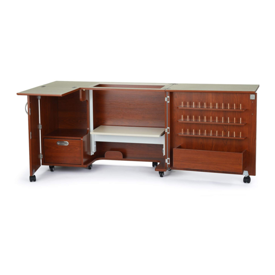
- Page 25 A ssembled Wallaby II Cabinet A SPECIAL NOTE ABOUT USING TABLETOP LEAVES: Do NOT extend the leaves until you have support panels in place. Doing so may damage the cabinet and void your warranty. Note in the illustration below that both of the leaves are supported by the front doors. The quilt panel is supported by the gate leg attached to the back of the cabinet.
-
Page 26: Limited Lifetime Warranty
Kangaroo Sewing Furniture is designed for residential use only. ARROW SHALL HAVE NO LIABILITY for ANY INCIDENTAL OR CONSEQUENTIAL DAMAGES OF ANY KIND and all such damages are EXCLUDED FROM THIS Warranty, such as loss of use, disassembly, transportation, labor, or damage to property on or near the product. - Page 27 Accessories to Complete Your Sewing Studio Custom Insert Arrow Sewing Chairs Enhance your sewing experience with a custom Arrow’s #1 Rated Height Adjustable Sewing Chair acrylic sewing insert! Custom acrylic sewing is a must have accessory for your dream sewing inserts are designed to fill the gap between your room! Cute, comfortable and convenient - our sewing machine and sewing cabinet’s lift opening...
Need help?
Do you have a question about the Wallaby II and is the answer not in the manual?
Questions and answers