
Subscribe to Our Youtube Channel
Related Manuals for Eagle TriFinder 2


Summary of Contents for Eagle TriFinder 2
- Page 1 Pub. 988-0143-651 www.eaglesonar.com TriFinder 2 Fish-finding & Depth Sounding Sonar Installation and Operation Instructions...
- Page 2 Eagle Electronics Marine-Tex is a trademark of Illinois Tool Works Inc. Eagle Electronics may find it necessary to change or end our policies, regulations, and special offers at any time. We reserve the right to do so without notice.
-
Page 3: Table Of Contents
8 transducer orientation and fish arches ... 9 Speed and temperature sensors ...10 Power connections ...13 Mounting sonar unit: in-dash, bracket or portable ...14 In-Dash installation ...14 Bracket installation ...15 Portable installation ...17 Operation and features ...18 Keyboard basics...18... - Page 4 System Setup ...38 Display backlights ...38 Display contrast ...39 Depth units of measure...39 Temperature units of measure ...40 Speed and distance log units of measure ...40 Reset distance log...41 Preset unit (reset all options) ...41 System Info (operating software version) ...42 Simulator ...42 Chart Setup ...43 Limit Search ...43...
-
Page 5: Introduction
The TriFinder 2 has several powerful features you can control by scrolling through easy-to-use menus with the arrow and menu keys. To get started with your Eagle sonar, first read the installation section. It contains instructions for mounting the sonar unit, the transducer and any optional accessories, such as a speed sensor. -
Page 6: Trifinder
Operates at speeds up to 70 mph (61 kts.) watts RMS power (typical). pends on transducer configuration and in- stallation, bottom composition and water conditions. All sonar units typically read deeper in fresh water than in salt water. sor or combo speed/temp sensor. speed/temp sensor. ... -
Page 7: Selecting A Transducer Location
If the transducer is not placed in a smooth flow of water, interference caused by bubbles and turbulence will show on the sonar's display in the form of random lines or dots whenever the boat is moving. - Page 8 4. If possible, route the transducer cable away from other wiring on the boat. Electrical noise from engine wiring, bilge pumps and aerators can be displayed on the sonar's screen. Use caution when routing the transducer cable around these wires.
-
Page 9: Shoot-Thru-Hull Vs. Transom Mounting
If you cruise or fish around lots of structure and cover, your transducer may be frequently kicking up from object strikes. If you wish, you may move the transducer a little higher for more protection. There are two extremes you should avoid. Never let the edge of the mounting bracket extend below the bottom of the hull. - Page 10 Ratchets Insert bolt and check transducer position on transom. 3. Assembling the transducer. Once you determine the correct posi- tion for the ratchets, assemble the transducer as shown in the fol- lowing figure. Don't tighten the lock nut at this time. Assemble transducer and bracket.
- Page 11 Transom Position transducer mount on transom and mark mounting holes. Side view shown at left and seen from above at right. 5. Attaching transducer to transom. Remove the transducer from the bracket and re-assemble it with the cable passing through the bracket over the bolt as shown in the following figures.
-
Page 12: Trolling Motor Bracket Installation
Align transducer centerline with hull bottom and attach to transom. 6. Route the transducer cable through or over the transom to the sonar unit. Make sure to leave some slack in the cable at the transducer. If possible, route the transducer cable away from other wiring on the boat. -
Page 13: Transducer Orientation And Fish Arches
(not included) to attach the transducer cable to the troll- ing motor shaft. Make sure there is enough slack in the cable for the motor to turn freely. Route the cable to the sonar unit and the trans- ducer is ready for use. -
Page 14: Speed And Temperature Sensors
Oil and dirt on the face will reduce the sensitivity or may even prevent operation. Speed/Temperature Sensors The TriFinder 2 can accept an optional speed sensor for showing speed and distance traveled. It can also accept an optional temperature sen- sor, or a combination speed/temp sensor. - Page 15 See the following charts for sample sensor combinations and cable con- nections. Transducer with no temperature sensor TriFinder 2 with external temperature sensor. This unit has a power cable with a connector for sensors. Transducers with built-in temp sensors are not compatible with TriFinder 2 units. TriFinder 2...
- Page 16 Transducer with no temperature sensor TriFinder 2 with external combination speed and temperature sensor. Transducers with built-in temp sensors are not compatible with Tri- Speed Sensor Installation If you wish to purchase an optional sensor for your unit, refer to the accessory ordering information inside the back cover of this manual.
-
Page 17: Power Connections
Speed sensor mounting configuration: side view (left) and rear view (right.) Route the sensor's cable through or over the transom to the sonar unit. If you need to drill a hole in the transom to pass the connector through, the required hole size is 7/8". -
Page 18: Mounting Sonar Unit: In-Dash, Bracket Or Portable
MOUNTING THE SONAR UNIT: In-Dash, Bracket or Portable You can install the sonar unit on the top of a dash with the supplied bracket. It can also be installed in the dash with an optional FM-4 mounting kit. -
Page 19: Bracket Installation
[0.14] R 6.35 [0.25] In-dash mounting template for TriFinder 2, showing dimensions. NOTE: The figure above is not printed to scale. A scaled template is available for free download from our web site, www.eaglesonar.com. If you use the supplied gimbal bracket, you may be interested in the optional GBSA-1 swivel bracket kit. - Page 20 [5.20] Front view (left) and side view (right) showing dimensions of the Tri- Finder sonar unit when mounted on gimbal bracket. Drill a 1-inch (25.4 mm) hole in the dash for the power and transducer cables. The best location for this hole is immediately under the gimbal bracket location.
-
Page 21: Portable Installation
You can use your TriFinder 2 on your boat or take it to the dock, on a float tube, on an ice fishing trip or use it as a second sonar in a friend's boat. -
Page 22: Operation And Features
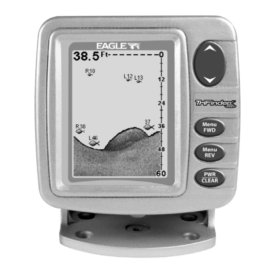
The unit sounds a tone when you press any key. This tells you the unit has accepted a command. Numbers in the photo correspond to key ex- planations below: Eagle TriFinder 2 Sonar, front view, showing screen and keyboard. 1. PWR/CLEAR (power and clear) This key appears in the manual text simply as turn the unit on and off. -
Page 23: Up And Down Arrows
. Use DOWN ARROW UP ARROW these keys to adjust virtually every feature and function on the sonar unit. MEMORY This unit has permanent memory that saves all user settings, even when power is removed. It does not require, nor does it use an internal backup battery, so you never have to worry about replacement batteries. -
Page 24: Display Opening Screen
If you don't want to wait, press the screen. When the sonar unit is first turned on and the backlight menu disap- pears, the display screen shows the Full Chart Page, or mode. The Fish I.D. feature is off. The depth range shows on the depth scale on the right side of the screen. -
Page 25: Screen Display Pages Or Modes
Chart is stopped at right, and "Stopped" warning message appears. SCREEN DISPLAY MODES or PAGES The TriFinder 2 has three screen display modes, or "Pages:" Full Chart page, Split Chart page and Large Digital page. The Page menu lets you select from three display modes, or pages. -
Page 26: Split Chart Page
The line at the top of the screen represents the surface. The bottom depth (as determined by the digital sonar) shows in the upper left corner. If an optional speed or temperature sensor is connected, digital displays for speed and/or tem- perature will also be shown. -
Page 27: Range - Automatic And Manual
NOTE: Temperature, speed, and distance require optional temperature or speed sensors. RANGE When turned on for the first time, the unit automatically adjusts the depth range according to water conditions. It always keeps the bottom displayed in the lower portion of the screen. You can over-ride the automatic range control and manually select a range. -
Page 28: Zoom
ZOOM The zoom feature enlarges all echoes on the screen. The 2X zoom doubles the size of the echoes on the display; the 4x zoom quadruples the echo size. To zoom the display, first press the pears. Use the arrow keys to select either 2X or 4X zoom, then press to clear the menu. -
Page 29: Sensitivity
ter column from 13 feet to about 39 feet, with 25 feet still in the middle of the screen. Important Tip: Your unit has the handy ability to quickly zoom in on any portion of the water column with just the touch of an arrow key. The Zoom Pan feature lets you rapidly move the zoomed area up and down to different depths. - Page 30 Fig. 1 Bait school Thermocline with fish Fish arches Fig. 3 These figures show results of different sensitivity levels on the same location. Fig. 1: Sensitivity at 87 percent, determined by Auto Sensitiv- ity. Typical of full auto mode. Fig. 2: Sensitivity set at 50 percent. Fig. 3: Sensitivity set at 20 percent.
- Page 31 100 percent, but the unit will limit your minimum setting. This prevents you from turning sensitivity down too low to allow automatic bottom tracking. When you change the setting with auto turned on, the unit will continue to track the bottom and make minor adjustments to the sensi- tivity level, with a bias toward the setting you selected.
-
Page 32: Grayline
Since Grayline shows the difference between strong and weak signals, adjusting the sensitivity may also require a different Grayline level. The level chosen by the sonar unit at power on is usually adequate for most conditions. Experiment with your unit to find the Grayline setting that's best for you. -
Page 33: Fish I.d
At left, underwater scene in normal fish arch mode. Right, Fish I.D. Fish I.D. is an easier way for a sonar novice to recognize a fishy signal return when he sees it. However, locating fish by symbol only has some limitations. -
Page 34: Fishtrack
Does that mean Fish I.D. is broken? No — the feature is simply inter- preting sonar returns in a specific way to help take some of the work out of reading the screen. Remember: Fish I.D. is one of the many tools we provide so you can analyze your sonar returns for maximum fish finding information. -
Page 35: Targettrack
TARGETTRACK The TriFinder 2 has the unique ability to "see" targets not only straight down, but also to the right and left, thanks to the BroadView™ trans- ducer. The TargetTrack feature shows you if the target is to the left, right or straight down. -
Page 36: Fishreveal Chart Mode
Target Track option in Fish ID menu. FISHREVEAL When displaying actual sonar returns, the FishReveal feature helps show fish targets hidden by surface clutter, thermoclines, weed beds and other cover with 10 levels of gray tones. Normal operation (with FishReveal turned off) shows the weakest ech- oes as black and the strongest in light gray. -
Page 37: Chart Scroll Speed And Hyperscroll
In Inverted FishReveal mode, the weakest echoes are black and the strongest echoes are white. Again, echoes in between vary in gray in proportion to their signal strength. In all modes, the Grayline control determines the range for black to white. At left, standard FishReveal mode. -
Page 38: Noise Reject And Asp (Advanced Signal Processing)
Reducing the chart speed may result in a shorter line that more closely resembles a regular fish return. At right, Scroll Speed menu at default 60 percent setting. At left, Scroll Speed menu, with unit set to HyperScroll mode. -
Page 39: Alarms
ALARMS The sonar unit has two different types of alarms, fish and depth. Fish Alarm The Fish Alarm sounds a tone when a fish symbol appears on the screen. The default setting is on, but the Fish I.D. feature must be turned on for fish alarms to work. -
Page 40: Shallow Alarm
To turn off the fish alarm without turning off fish symbols, press MENU until appears. Press to select , then DOWN DOWN ARROW LARM press to clear the menu. Repeat the above steps to turn the alarm back on, but press to select before clearing the menu. -
Page 41: Deep Alarm
to decrease it. The number in the shallow alarm’s menu DOWN ARROW box shows the current shallow alarm setting. When the number reaches the desired setting, press depth goes shallower than the alarm’s setting, an alarm tone sounds and a message box appears on the screen. Press to silence the alarm. -
Page 42: System Setup
SYSTEM SETUP To customize the display, press until the MENU DOWN YSTEM ETUP menu appears, then press . The display contrast, units of UP ARROW measure, temperature, and system information screens are all under this menu. The Contrast menu appears first. Press the MENU UP keys to cycle through the menus. -
Page 43: Display Contrast
DISPLAY CONTRAST The unit’s display contrast is adjustable to suit different lighting condi- tions. This will help you see the screen from different angles or at vari- ous times of the day. The default setting is 50 percent. To adjust the contrast, press until the menu ap- MENU DOWN... -
Page 44: Temperature Units Of Measure
TEMPERATURE UNITS OF MEASURE This unit can show the temperature (if a temperature sensor is attached) in degrees Fahrenheit or Celsius. To change the unit of measure, press until the menu appears. Press , then MENU DOWN UP ARROW YSTEM press until the menu appears. -
Page 45: Reset Distance Log
RESET DISTANCE LOG You can reset the distance log to zero with this command. Press MENU until appears, then press . Press until DOWN UP ARROW MENU YSTEM menu appears. Press and the log returns to UP ARROW ESET zero. Press to clear the menu. -
Page 46: System Info (Operating Software Version)
SYSTEM INFO To show the operating software system information, press MENU DOWN until the menu appears, then press . Press UP ARROW MENU DOWN YSTEM until the screen appears. Press to clear the screen. YSTEM System Info screen. SIMULATOR This unit has a built-in simulator that shows a simulated bottom signal with fish signals. -
Page 47: Chart Setup
If you turn on your unit before attaching a transducer, it may enter a demo mode. The words "demo mode" flash on the bottom of the screen and a sonar chart plays much like the Simulator feature. Un- like the simulator, the demo mode is for demonstration only, and will automatically stop as soon as you turn on the unit with a transducer attached. -
Page 48: Digital Data Size For Depth, Temperature, Speed And Distance Log
Try this command only if you are in deep water, traveling at high speed, and notice a reduction in detail on the sonar chart. When Limit Search is turned on, the digital sonar will limit its search for the bottom to the depth range you have set for the sonar chart. -
Page 49: Scales
Menus for changing digital number size. To change any of these options, press appears, then press list and display the desired menu, then use the the desired number size or turn the numbers off. Press the clear the menus. SCALES The depth scale between the upper and lower limit on the right side of the screen can be turned on or off. -
Page 50: Troubleshooting
Unit freezes, locks up, or operates erratically: 1. Electrical noise from the boat's motor, trolling motor, or an accessory may be interfering with the sonar unit. Rerouting the power and trans- ducer cables away from other electrical wiring on the boat may help. - Page 51 1. The transducer may be in turbulent water. It must be mounted in a smooth flow of water in order for the sonar to work at all boat speeds. Air bubbles in the water disrupt the sonar signals, interfering with its ability to find the bottom or other targets.
- Page 52 For example, turn on the bilge pump and view the sonar display for noise. If no noise is present, turn the pump off, then turn on the VHF radio and transmit.
-
Page 53: Warranty And Service Information
FULL ONE-YEAR WARRANTY "We," "our," or "us" refers to EAGLE ELECTRONICS, a division of LEI, the manufacturer of this product. "You" or "your" refers to the first person who purchases this product as a consumer item for personal, family, or household use. -
Page 54: How To Obtain Service
8 a.m. to 5 p.m. Central Standard Time, M-F Eagle Electronics may find it necessary to change or end our shipping policies, regulations, and special offers at any time. We reserve the right to do so without notice. -
Page 55: Accessory Ordering Information For All Countries
1. Always use the original shipping container and filler material the product was packed in. 2. Always insure the parcel against damage or loss during shipment. Eagle does not assume responsibility for goods lost or damaged in transit. 3. For proper testing, include a brief note with the product describing the problem. -
Page 56: Visit Our Website
Eagle Pub. 988-0143-651 Printed in USA 091902 Visit our web site: www.eaglesonar.com © Copyright 2002 All Rights Reserved Eagle Electronics...
Need help?
Do you have a question about the TriFinder 2 and is the answer not in the manual?
Questions and answers
Как увеличить яркость экрана