
Related Manuals for INGENIA Triton Core


Summary of Contents for INGENIA Triton Core
- Page 1 Triton Core Product Manual Edition 05/29/2017 For the most up to date information visit the online manual. INGENIA-CAT S.L. 8-14 MARIE CURIE, ADVANCED INDUSTRY PARK 08042 BARCELONA...
-
Page 2: Table Of Contents
Power and operation signalling LED outputs....................31 CAN signalling LED outputs (only TRI-x/48-C-P)....................32 EtherCAT signalling LED outputs (only TRI-x/48-E-P) ..................33 Product Dimensions Triton Core with CAN (TRI-x/48-C-P) ........................35 Triton Core with EtherCAT (TRI-x/48-E-P)......................36 Application Software Configuration ..............................38 Applications................................. -
Page 3: General Information
S.L.. Such information is supplied solely for the purpose of assisting users of the product in its installation. INGENIA-CAT S.L. rejects all liability for errors or omissions in the information or the product or in other documents mentioned in this document. ... - Page 4 Triton Core Product Manual | General Information Telephone: +34 932 917 682 E-mail: hello@ingeniamc.com site: www.ingeniamc.com mailto:HELLO@INGENIAMC.COM http://www.ingeniamc.com/ INGENIA | 05/29/2017...
-
Page 5: Safety Information
Triton Core Product Manual | Safety Information 3 Safety Information About this manual Read carefully this chapter to raise your awareness of potential risks and hazards when working with the Triton Servo Drive. To ensure maximum safety in operating the Triton Servo Drive, it is essential to follow the procedures included in this guide. -
Page 6: Product Description
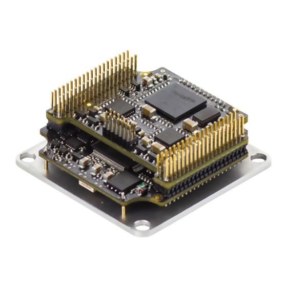
Triton Core Product Manual | Product Description 4 Product Description The Triton Core Servo Drive is an ultra-compact solution designed to be integrated in a motherboard or backplane as a component. It provides top performance, advanced networking and built-in safety, as well as a fully featured motion controller. - Page 7 Triton Core Product Manual | Product Description Product Ordering part number Status Image ACTIVE Triton Core TRI-7/48-C-P ACTIVE TRI-4/48-C-P ACTIVE TRI-1/48-C-P ACTIVE TRI-7/48-E-P ACTIVE TRI-4/48-E-P ACTIVE TRI-1/48-E-P INGENIA | 05/29/2017...
-
Page 8: Specifications
TRI-7/48-E-C ACTIVE TRI-4/48-E-C ACTIVE TRI-1/48-E-C 4.2 Specifications A list of features of the Triton Core Servo Drive is shown next. For further details, please check the Operational characteristics section below. (see page 14) Electrical and power specifications Part number →... - Page 9 Triton Core Product Manual | Product Description 0.67 A Nominal phase continuous current 3.33 A 5.6 A (BLDC mode) (with heatsink) (with heatsink) Nominal phase continuous current 6.3 A (DC mode) (with heatsink) (with heatsink) Maximum phase peak current 8.5 A ...
- Page 10 Triton Core Product Manual | Product Description Sensors for commutation • Digital Halls (Trapezoidal) • Analog Halls (Sinusoidal / Trapezoidal) (brushless motors) • Quad. Incremental encoder (Sinusoidal / Trapezoidal) • PWM encoder (Sinusoidal / Trapezoidal) • Analog potentiometer (Sinusoidal / Trapezoidal) • Sin-Cos encoder (Sinusoidal / Trapezoidal) •...
- Page 11 Triton Core Product Manual | Product Description Inputs/outputs and protections Part number → TRI-1/48-y-P TRI-4/48-y-P TRI-7/48-y-P Inputs and outputs General purpose: • 4 x non-isolated single-ended digital inputs. 3.3 V levels, 5.5 V tolerant • 2 x non-isolated high speed differential digital inputs. 3.3 V levels, 5.5 V tolerant...
-
Page 12: Hardware Revisions
Triton Core Product Manual | Product Description Motor brake Motor brake output (by means of an external switched element) through digital outputs. Communications Part number → TRI-x/48-C-P TRI-x/48-E-P USB 2.0. The board can be supplied from USB for configuration purposes but will not power the motor. -
Page 13: Absolute Maximum Ratings
Hardware revision is screen printed on the board. 4.4 Absolute maximum ratings The following information represent the environmental and electrical limits of Triton Core. Notice this does not represent an operational conditions limit, but a limit before permanent damage or destruction. References to pin names and pin group names can be found in the Pinout... -
Page 14: Operational Characteristics
Note 4: Absolute maximum current for all part numbers Note 5: Absolute maximum junction temperature 4.5 Operational characteristics The following information represent the recommended operation limits of Triton Core, among which its response will remain between known boundaries. References to pin names and pin group names can be found the Pinout section. -
Page 15: Output Supplies And Voltage Reference
Triton Core Product Manual | Product Description Standby power Power stage disabled — — STB( consumption (TRI-x/ CAN) 48-C-P) Standby power Power stage disabled — — STB( consumption (TRI-x/ ECAT) 48-E-P) 4.5.2 Output supplies and voltage reference Parameter Conditions / UNIT Comments +5V_D output voltage 4.75... -
Page 16: System Monitoring
Triton Core Product Manual | Product Description Continuous phase current in Limited by ADC range. — — TRA( Trapezoidal mode (TRI-4/48-y-P) TRI-4) Continuous phase current in Limited by ADC range. — — SIN(T Sinusoidal mode (TRI-4/48-y-P) RI-4) Continuous phase current in DC -6.3... -
Page 17: Protections
Triton Core Product Manual | Product Description Phase current sensing — ±1 ±2 tolerance (all part numbers) DC bus voltage reading range — 73.6 DC bus voltage reading — ±1 ±3 tolerance Board temperature reading — — ±5 tolerance 4.5.5 Protections Parameter... -
Page 18: Inputs
Triton Core Product Manual | Product Description 4.5.6 Inputs Parameter Conditions / Comments High-level input INPUT_x, HS_INPUT_x, — — IH(3.3 voltage (3.3 V #BROKEN_WIRE_IN, UART_RX, tolerant inputs) CAN_TTL_RX and ABS_ENCODER_SDI pins Low-level input — — INPUT_x, HS_INPUT_x, IL(3.3) voltage (3.3 V #BROKEN_WIRE_IN, UART_RX,... -
Page 19: Outputs
Triton Core Product Manual | Product Description 4.5.7 Outputs Parameter Conditions / Comments High-level voltage on output = 50 μA — — OUTPUT pins * Low-level voltage on output pins — — = -50 μA OUTPUT IOUT(3 Output current on 3.3 V tolerant —... -
Page 20: Equivalent Circuits
Triton Core Product Manual | Product Description Power stage switching frequency — SW(RA NGE) configurable range * Torque loop refresh frequency — — TORQ Position / velocity loops refresh — — SERVO frequency Frequency tolerance Over operating — — ±150 temperature range Maximum DC Bus utilisation —... - Page 21 Triton Core Product Manual | Product Description 10 kHz 10 ksps HALL_x Analog hall inputs * Motor temperature MOTOR_TEM 0.8 kHz 10 ksps P_IN input * Torque Off input. #TORQUE_O FF_IN #BROKEN_W 1 ksps Encoder broken wire IRE_IN protection input. Analog and digital...
-
Page 22: Architecture
Note 4: It is recommended to set the braking resistor PWM duty to 100 %. In this case, the switching frequency depends on the characteristics of the re-injection or braking action itself. 4.7 Architecture This diagram represent the main hardware elements of Triton Core, and how they relate to each other. http://ingeniamc.com/support/triton INGENIA | 05/29/2017... - Page 24 Triton Core Product Manual | Product Description INGENIA | 05/29/2017...
-
Page 25: Pinout
Triton Core Product Manual | Pinout 5 Pinout The following diagram and pinout table defines the functionality of each pin in Triton Core Servo Drive. For further information, see Operational characteristics in Product Description section. (see page 6) Pinout change from previous version Note that the pin numbering is different from the first version of the Triton Core datasheet. - Page 26 Triton Core Product Manual | Pinout 9, 10, Power Protective Earth (Internally connected to driver Motor 11, 12 mounting plate / chassis) power PHASE_ Power Motor phase C for 3-phase motors (do not connect for DC motors or voice coils) PHASE_...
- Page 27 Triton Core Product Manual | Pinout ENCODE Input B channel input for a single ended digital encoder. B+ R_B+ terminal for a differential digital encoder ENCODE Input B- terminal for a differential digital encoder R_B- OUTPUT Output Output Digital output 6 OUTPUT...
- Page 28 Triton Core Product Manual | Pinout INPUT_2 Input Digital input 2 Digital Inputs INPUT_1 Input Digital input 1 UART_TX Output UART Transmit terminal for UART stream in 3.3 V TTL levels UART_R Input Receive terminal for UART stream in 3.3 V TTL levels...
- Page 29 Triton Core Product Manual | Pinout USB_DAT Bidirec Positive terminal for USB data stream. tional USB_SU Power USB +5 V bus terminal. Internal Logic circuitry can be PPLY supplied from this pin USB_DAT Bidirec Negative terminal for USB data stream. tional #TORQU...
- Page 30 Triton Core Product Manual | Pinout PHY0_TX Output Negative terminal for the Transmitter of the EtherCAT Port 0 PHY0_RX Input Negative terminal for the Receiver of the EtherCAT Port INGENIA | 05/29/2017...
-
Page 31: Signalling Leds
6 Signalling LEDs Triton Core Servo Drive does not include any signalling LED, but has some dedicated pins to drive external LEDs. With the use of 5 dedicated LED outputs and some additional signals, the following status LEDs can be drived. -
Page 32: Can Signalling Led Outputs (Only Tri-X/48-C-P)
6.2 CAN signalling LED outputs (only TRI-x/48-C-P) Two LED signal outputs provide information about the CANopen communication status, according to CiA 303-3 recommendations . LED_CAN_ERROR and LED_CAN_RUN signals (used for EtherCAT operation in the Triton Core part number TRI- x/48-E-P), are intended to drive a red ERROR LED and a green RUN LED, respectively. ... -
Page 33: Ethercat Signalling Led Outputs (Only Tri-X/48-E-P)
EtherCAT signalling LED outputs (only TRI-x/48-E-P) Four EtherCAT LED signals provide information regarding communication status according to EtherCAT specification. LED_ECAT_RUN and LED_ECAT_ERROR signals (used for CAN operation in the Triton Core part number TRI-x/ 48-C-P), are intended to drive a red ERROR LED and a green RUN LED, respectively. The signalling fits the... - Page 34 Triton Core Product Manual | Signalling LEDs LED_ECAT_LINK0 and LED_ECAT_LINK1 signals are intended to drive YELLOW Link 0 and Link 1 LEDs, typically integrated in the RJ45 connector housing to indicate the state of the physical link activity on each port. Signalling fits the following states table:...
-
Page 35: Product Dimensions
7 Product Dimensions Triton Core Servo Drive has a 43 mm x 43 mm footprint, and the maximum height depends on the Triton part number. All Triton variants are provided with 4 x Ø 3.3 mm holes in a 37 mm x 37 mm square for M3 screws mounting. -
Page 36: Triton Core With Ethercat (Tri-X/48-E-P)
3D Model For further detail, download the STEP 3D model and PDF 3D for the Triton Core TRI-x/xx-C-P. Note that the model is simplified: it does not show all the internal components, but does show the major volumes. 7.2 Triton Core with EtherCAT (TRI-x/48-E-P) Next figure shows mechanical dimensions in mm. - Page 37 3D Model For further detail, download the STEP 3D model and PDF 3D for the Triton Core TRI-x/xx-E-P. Note that the model is simplified: it does not show all the internal components, but does show the major volumes. http://ingeniamc.com/support/triton INGENIA | 05/29/2017...
-
Page 38: Application Software
Triton Core Product Manual | Application Software 8 Application Software 8.1 Configuration To connect, configure, tune your motor or upgrade the firmware of the Triton Core, install Ingenia Motion suite. The software package includes USB drivers. Keep the firmware updated Before configuring your drive for a new application make sure you have upgraded to the latest firmware revision. -
Page 39: Service
GIZATECH www.gizatech.eu/ comercial@milexia.es ANTRIMON MOTION Switzerland www.antrimon.com motion@antrimon.com Turkey FEMSAN www.femsan.com melike@femsan.com United MOTION CONTROL Kingdom PRODUCTS www.motioncontrolproducts.com info@motioncontrolproducts.com United States NAMPRO www.namproinc.com sales@namproinc.com United States GROUP SIX www.grp6.com ingenia@grp6.com INGENIA-CAT S.L. 8-14 MARIE CURIE, ADVANCED INDUSTRY PARK 08042 BARCELONA...
Need help?
Do you have a question about the Triton Core and is the answer not in the manual?
Questions and answers