Vega VEGADIS 61 Operating Instructions Manual
Hide thumbs
Also See for VEGADIS 61:
- Operating instructions manual (28 pages) ,
- Product information (12 pages)
Table of Contents
Advertisement
Quick Links
Advertisement
Table of Contents

Related Manuals for Vega VEGADIS 61


Summary of Contents for Vega VEGADIS 61
- Page 1 Operating Instructions VEGADIS 61 8888 8888...
-
Page 2: Table Of Contents
CE conformity ..........7 Safety instructions for Ex areas ....7 Environmentally responsible behaviour ..7 3 Product description Configuration ..........8 Principle of operation ......... 9 Adjustment ..........9 Storage and transport ......10 4 Mounting ............11 VEGADIS 61... - Page 3 Set-up procedure ........17 7 Maintenance and failure rectification Maintenance ..........18 Modify the instrument ......18 Repair the instrument ......19 8 Dismounting Dismounting procedure ......20 Disposal ..........20 Supplement Technical data ..........21 Dimensions ............23 VEGADIS 61...
-
Page 4: About This Document
1 About this document 1.1 Function This operating instructions manual has all the infor- mation for quick set-up and safe operation of VEGADIS 61. Please read this manual before you start set-up. 1.2 Target group All instructions described in this manual must be carried out only by trained and authorized personnel. - Page 5 About this document • List The dot set in front indicates a list with no implied sequence. –> Action This arrow indicates a single action. Sequence Numbers set in front indicate successive steps in a procedure. VEGADIS 61...
-
Page 6: For Your Safety
VEGA personnel. 2.2 Appropriate use VEGADIS 61 is an external indication and adjustment unit for level and pressure transmitters of series 60. 2.3 Warning about misuse Inappropriate or incorrect use of the instrument can give rise to application-specific hazards, e.g. -
Page 7: Ce Conformity
For your safety 2.5 CE conformity VEGADIS 61 is in CE conformity with EMC (89/336/ EWG) and NSR (73/23/EWG) and fulfils the Namur recommendations NE 21. The conformity has been judged according to the following standards: emission EN 61326: 1997... -
Page 8: Product Description
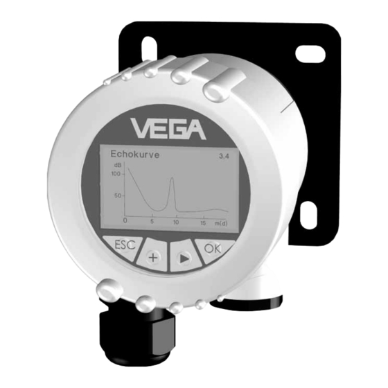
The components are available in different versions. Housing cover with indicating and ad- justment module PLICSCOM located below Mounting plate housing with electronics Fig. 1: Example of VEGADIS 61 with plastic housing and mounting plate for wall mounting VEGADIS 61... -
Page 9: Principle Of Operation
Level sensors VEGAFLEX 61, 62 and 65. Fig. 2: Connection of VEGADIS 61 to the sensor VEGADIS 61 is connected to the sensor via a four- Power supply wire, screened standard cable with a length of max. 25 m. An extra power supply is not required. -
Page 10: Storage And Transport
Dispose of the packing material via specialised recycling companies. Packing material carton/paper Storage and transport tem- Storage and transport temperature:-40 … perature rel. humidity: 20 … 85 % See Supplement, Technical data, Ambient conditions VEGADIS 61... -
Page 11: Mounting
Mounting 4 Mounting Select installation position VEGADIS 61 functions in any installation position. It is mounted either on a mounting plate or rail 35 x 7.5 acc. to DIN EN 50 022. The housing can be rotated 330° without using any tools. - Page 12 Fig. 4: Measures against moisture ingress Rain and condensed water can thus drain off, espe- cially in outdoor installations, in rooms where humid- ity is expected (e.g. caused by cleaning processes) or on cooled or heated vessels. VEGADIS 61...
-
Page 13: Connecting To The Sensor
VEGADIS 61. Select connection cable VEGADIS 61 is connected with standard four-wire cable to the sensor. An outer diameter of 5 ... 9 mm ensures the seal effect of the cable entry. -
Page 14: Connection Steps
4 Dismantle the connection cable approx. 10 cm, remove approx. 1 cm insulation from core wires 5 Push the cable through the cable entry into VEGADIS 61 6 Raise the opening lug of the terminals with a screwdriver 7 Insert the core ends into the open terminals ac-... - Page 15 12 Tighten the compression nut of the cable entry firmly, the seal ring must completely encircle the cable 13 Press PLICSCOM lightly onto the electronics and turn it to the right until it snaps in 14 Screw on the housing cover. The electrical connection is finished. VEGADIS 61...
-
Page 16: Wiring Plans
Earth terminal Fig. 7: Top view of the combined electronics and connection compart- ment Wiring plan VEGADIS 61 VEGABAR/ VEGAFLEX Terminal 5 –> Terminal 5 Terminal 6 –> Terminal 6 Terminal 7 –> Terminal 7 Terminal 8 –> Terminal 8... -
Page 17: Set-Up With The Indicating And Adjustment Module Plicscom
6.2 Set-up procedure The set-up and adjustment of the sensors must be carried out according to the operating instructions of the sensor and the indicating and adjustment module PLICSCOM. VEGADIS 61... -
Page 18: Maintenance And Failure Rectification
7.2 Modify the instrument PLICSCOM mounting or PLICSCOM can be mounted on or dismounted from dismounting VEGADIS 61 at any time. The power supply must not be interrupted. For dismounting, please proceed as follows: 1 Remove housing cover 2 Turn PLICSCOM slightly to the left and remove Fig. -
Page 19: Repair The Instrument
Maintenance and failure rectification 7.3 Repair the instrument If it is necessary to repair VEGADIS 61, please send the instrument to the following address: VEGA Grieshaber KG Repair Department Am Hohenstein 113 77761 Schiltach Germany VEGADIS 61... -
Page 20: Dismounting
"Connecting to the sensor" and carry out the steps in reverse order. 8.2 Disposal VEGADIS 61 consists of materials which can be recy- cled by specialised recycling companies. We have purposely designed the electronic modules to be easily separable. Mark the instrument as scrap and dispose of it according to government regulations. -
Page 21: Supplement Technical Data
0.35 kg Ambient conditions Ambient temperature -20 … +70°C Storage and transport temperature -40 … +85°C Adjustment module PLICSCOM Supply and data transfer with VEGADIS 61 via sliding contacts (I²C-Bus) Display LC-Display in Full-Dot-Matrix Adjustment elements IP 20 Materials – housing –... - Page 22 Supplement Electrical protective measures Protection IP 66/IP 67 Protection class Overvoltage category Approvals ATEX II 1G, 2G EEx ia IIC T6 VEGADIS 61...
-
Page 23: Dimensions
Supplement Dimensions VEGADIS 61 ca. 69,5 ø 77 M20x1 M20x1,5 VEGADIS 61... - Page 24 VEGA Grieshaber KG Am Hohenstein 113 77761 Schiltach Germany Phone (07836) 50-0 (07836) 50-201 E-Mail info@de.vega.com www.vega.com ISO 9001 All statements concerning scope of delivery, application, use and operating conditions of the sensors and process- ing systems correspond to the latest information at the time of printing.
Need help?
Do you have a question about the VEGADIS 61 and is the answer not in the manual?
Questions and answers