Vega VEGAFLEX 83 Operating Instructions Manual
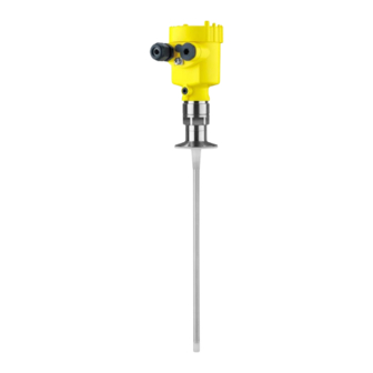
Tdr sensor for continuous level and interface measurement of liquids
Hide thumbs
Also See for VEGAFLEX 83:
- Operating instructions manual (100 pages) ,
- Operating instruction (92 pages) ,
- Quick setup manual (20 pages)

Related Manuals for Vega VEGAFLEX 83


Summary of Contents for Vega VEGAFLEX 83
- Page 1 Operating Instructions TDR sensor for continuous level and interface measurement of liquids VEGAFLEX 83 Modbus and Levelmaster protocol PFA coated rod and cable probe Document ID: 51518...
-
Page 2: Table Of Contents
Parameter adjustment with PACTware ................51 Set instrument address ....................53 Set up with the quick setup ..................... 53 Save parameter adjustment data..................55 Diagnosis, asset management and service ................ 56 Maintenance ........................56 VEGAFLEX 83 • Modbus and Levelmaster protocol... - Page 3 11.8 Industrial property rights ....................87 11.9 Trademark ........................87 Safety instructions for Ex areas: Take note of the Ex specific safety instructions for Ex applications. These instructions are attached as documents to each instrument with Ex approval and are part of the operating instructions. Editing status: 2023-05-23 VEGAFLEX 83 • Modbus and Levelmaster protocol...
-
Page 4: About This Document
Symbols used Document ID This symbol on the front page of this instruction refers to the Docu- ment ID. By entering the Document ID on www.vega.com you will reach the document download. Information, note, tip: This symbol indicates helpful additional infor- mation and tips for successful work. -
Page 5: For Your Safety
During work on and with the device, the required personal protective equipment must always be worn. Appropriate use VEGAFLEX 83 is a sensor for continuous level measurement. You can find detailed information about the area of application in chapter " Product description". Operational reliability is ensured only if the instrument is properly used according to the specifications in the operating instructions manual as well as possible supplementary instructions. -
Page 6: Namur Recommendations
That is why we have introduced an environment management system with the goal of continuously improving company environmental pro- tection. The environment management system is certified according to DIN EN ISO 14001. Please help us fulfil this obligation by observing the environmental instructions in this manual: • Chapter " Packaging, transport and storage" • Chapter " Disposal" VEGAFLEX 83 • Modbus and Levelmaster protocol... -
Page 7: Product Description
Scope of this operating This operating instructions manual applies to the following instrument instructions versions: • Hardware from 1.0.0 • Software from 1.3.0 • Only for instrument versions without SIL qualification Type label The type label contains the most important data for identification and use of the instrument: VEGAFLEX 83 • Modbus and Levelmaster protocol... - Page 8 Alternatively, you can access the data via your smartphone: • Download the VEGA Tools app from the " Apple App Store" or the " Google Play Store" • Scan the QR-code on the type label of the device or •...
-
Page 9: Principle Of Operation
3 Product description Principle of operation Application area The VEGAFLEX 83 is a level sensor with coated cable or rod probe for continuous level or interface measurement, particularly suitable for applications in the chemical industry. Functional principle - High frequency microwave pulses are guided along a steel cable or level measurement a rod. - Page 10 Example: upper medium dielectric constant 2, lower medium at least dielectric constant 12. Gas phase (L3) • Air or gas mixture • Gas phase - dependent on the application, gas phase does not always exist (d2 = 0) VEGAFLEX 83 • Modbus and Levelmaster protocol...
-
Page 11: Packaging, Transport And Storage
The integrated Bluetooth module (optional) enables wireless adjust- ment via standard adjustment devices. VEGACONNECT The interface adapter VEGACONNECT enables the connection of communication-capable instruments to the USB interface of a PC. VEGAFLEX 83 • Modbus and Levelmaster protocol... - Page 12 10 m (32.8 ft) to the sensor by using a connection cable. Centering If you mount the VEGAFLEX 83 in a bypass tube or standpipe, you have to avoid contact to the bypass tube by using a spacer at the probe end.
-
Page 13: Mounting
These are mainly: • Active measuring component • Process fitting • Process seal Process conditions in particular are: • Process pressure • Process temperature VEGAFLEX 83 • Modbus and Levelmaster protocol... -
Page 14: Mounting Instructions
The guided microwave principle requires a metallic surface on the process fitting. Therefore, in plastic vessels, etc., use an instru- ment version with flange (from DN 50) or place a metal sheet (ø > 200 mm/8 in) beneath the process fitting when screwing it in. Make sure that the plate has direct contact with the process fitting. When mounting rod or cable probes in vessels without metal walls, e.g. in plastic vessels, the measured value can be influenced by strong electromagnetic fields (emitted interference according to EN 61326: class A). In this case, use a probe with coaxial version. VEGAFLEX 83 • Modbus and Levelmaster protocol... - Page 15 In such cases, always carry out a false signal suppression after mounting. You can find further information under " Setup procedure". ≤ 150 mm ( 5.91") DN25 ... DN150 > DN150 ... DN200 ≤ 100 mm ( 3.94") Fig. 6: Mounting socket When welding the nozzle, make sure that the nozzle is flush with the vessel top. VEGAFLEX 83 • Modbus and Levelmaster protocol...
- Page 16 - measure- ment in these areas is not possible (blocking distance). The length of the cable can be used all the way to the end only when measuring VEGAFLEX 83 • Modbus and Levelmaster protocol...
- Page 17 Suitable retaining elements are also available from us. Size Article no. Type M16, " 32880 Detent edged ring Gross VS KD M20, " 32881 Detent edged ring Gross VS KD M24, " 32882 Retaining washer Schnorr VS, Schnorr S VEGAFLEX 83 • Modbus and Levelmaster protocol...
- Page 18 Sealing surface The flange screws of VEGAFLEX 83 must be tightened with a torque of approx. 60 Nm (44 lbf ft) so that the PTFE washer seals reliably. Note: We recommend, retightening the screws in regular intervals depend- ing on process pressure and temperature VEGAFLEX 83 • Modbus and Levelmaster protocol...
-
Page 19: Connecting To Power Supply And Bus System
In the case of instrument housings with self-sealing NPT threads, it is not possible to have the cable entries screwed in at the factory. The free openings for the cable glands are therefore covered with red dust protection caps as transport protection. VEGAFLEX 83 • Modbus and Levelmaster protocol... -
Page 20: Connecting
1 cm (0.4 in) of insulation from the ends of the individual wires 5. Insert the cable into the sensor through the cable entry Fig. 10: Connection steps 5 and 6 - Single chamber housing 6. Insert the wire ends into the terminals according to the wiring plan VEGAFLEX 83 • Modbus and Levelmaster protocol... -
Page 21: Wiring Plan, Single Chamber Housing
Make sure that the slid switch (5) with all sen- sors of the chain is set to "off". With the last sensor you have to set the slide switch (5) to position "on". Please also take note of the information in the annex " Basics Mod- bus". VEGAFLEX 83 • Modbus and Levelmaster protocol... - Page 22 1 2 = Power supply 3 4 = Modbus Data 5 6 = Power supply addr. 7 8 = Modbus Data 5 6 7 8 Fig. 12: Electronics compartment - Connection with stub Voltage supply Signal output Ground terminal in the housing VEGAFLEX 83 • Modbus and Levelmaster protocol...
-
Page 23: Set Instrument Address
Available hardware addresses: • Hardware address - Levelmaster: 000 … 030 • Hardware address - Modbus: 000 … 245 Set the instrument address with the three rotary switches on the electronics module. VEGAFLEX 83 • Modbus and Levelmaster protocol... -
Page 24: Switch-On Phase
• Status byte goes to fault value Then the actual measured value is output to the signal cable. The value takes into account settings that have already been carried out, e.g. default setting. VEGAFLEX 83 • Modbus and Levelmaster protocol... -
Page 25: Set Up The Sensor With The Display And Adjustment Module
The display and adjustment module is powered by the sensor, an ad- ditional connection is not necessary. Fig. 14: Installing the display and adjustment module in the electronics compart- ment of the single chamber housing Note: If you intend to retrofit the instrument with a display and adjustment module for continuous measured value indication, a higher lid with an inspection glass is required. VEGAFLEX 83 • Modbus and Levelmaster protocol... -
Page 26: Adjustment System
The pen oper- ates the four keys of the display and adjustment module right through the closed lid (with inspection window) of the sensor housing. VEGAFLEX 83 • Modbus and Levelmaster protocol... - Page 27 [OK] will not be saved. Switch-on phase After switching on, the VEGAFLEX 83 carries out a short self-test where the device software is checked. The output signal transmits a fault signal during the switch-on phase. The following information is displayed on the display and adjustment module during the startup procedure: •...
-
Page 28: Parameter Adjustment - Quick Setup
Info: Instrument name, hardware and software version, date of manu- facture, instrument features Note: For optimum setting of the measuring point, the individual submenu items in the main menu item " Setup" should be selected one after VEGAFLEX 83 • Modbus and Levelmaster protocol... - Page 29 Here you can assign a suitable measurement loop name. Push the " OK" key to start the editing. With the " +" key you change the sign and with the " ->" key you jump to the next position. VEGAFLEX 83 • Modbus and Levelmaster protocol...
- Page 30 You have the option of choosing the demonstration mode. This mode is only suitable for test and demonstration purposes. In this mode, the sensor ignores the parameters of the application and reacts immedi- ately to any change. VEGAFLEX 83 • Modbus and Levelmaster protocol...
- Page 31 If you want the dielectric constant to be determined by the instrument, you have to enter the measured or known distance to the interface. Note: The dielectric constant can only be reliably determined if two different media and a sufficiently large interface are present. VEGAFLEX 83 • Modbus and Levelmaster protocol...
- Page 32 The distance refers tot he sensor reference plane (seal surface of the process fitting). Max. adjustment interface This menu item is only available if you have selected interface meas- urement under the menu item " Application". VEGAFLEX 83 • Modbus and Levelmaster protocol...
- Page 33 We generally recommend carrying out a false signal suppression to achieve the best possible accuracy. This should be done with the lowest possible level so that all potential interfering reflections can be detected. Proceed as follows: Select first if the probe is covered or uncovered. VEGAFLEX 83 • Modbus and Levelmaster protocol...
- Page 34 Corresponding linearisation curves are preprogrammed for these vessels. They represent the correlation between the level percentage and vessel volume. The linearisation applies to the measured value indication and the output. By activating the appropriate curve, the volume percentage of VEGAFLEX 83 • Modbus and Levelmaster protocol...
- Page 35 Fig. 17: Vessel height and socket correction value D Vessel height +h Positive socket correction value -h Negative socket correction value Modbus variables In this menu item, all Modbus variables of the outputs were collected. VEGAFLEX 83 • Modbus and Levelmaster protocol...
- Page 36 The procedure is described in the following. The following submenu points are available: The submenu points are described below. Menu language This menu item enables the setting of the requested national lan- guage. VEGAFLEX 83 • Modbus and Levelmaster protocol...
- Page 37 The function depends on the strength of the operating voltage, see " Technical data". To maintain the function of the device, the lighting is temporarily switched off if the power supply is insufficient. In delivery status, the lighting is switched on. VEGAFLEX 83 • Modbus and Levelmaster protocol...
- Page 38 Setup - Application", the peak values of the interface measurement are displayed in addition to the peak values of the level measurement. In another window you can carry out a reset of the two peak values separately. VEGAFLEX 83 • Modbus and Levelmaster protocol...
- Page 39 In this menu item you can simulate measured values via the output. This allows the signal path to be tested, e.g. through downstream indicating instruments or the input card of the control system. Select the requested simulation variable and set the requested value. VEGAFLEX 83 • Modbus and Levelmaster protocol...
- Page 40 6.5.4 Additional adjustments Date/Time In this menu item, the internal clock of the sensor is set. VEGAFLEX 83 • Modbus and Levelmaster protocol...
- Page 41 Min. adjustment - Level Distance: Probe length - take dead band into account Accept adjustment of the level measurement? Max. adjustment - Interface 100 % Max. adjustment - Interface Distance: 0.000 m(d) - note blocking distances VEGAFLEX 83 • Modbus and Levelmaster protocol...
- Page 42 Device memory - Measured value memory - Stop with meas- Not active ured value Device memory - Measured value memory - Stop recording Not active when memory is full Menu - Additional adjustments Menu item Default value 0000 Date Actual date VEGAFLEX 83 • Modbus and Levelmaster protocol...
- Page 43 We recommend to save the instrument adjustments. In case of an electronics exchange the saved parameter adjustment data relieve this process. Scaling level Since scaling is very extensive, scaling of the level value was divided into two menu items. VEGAFLEX 83 • Modbus and Levelmaster protocol...
- Page 44 In this menu item, all settings of the instrument interfaces are col- Interface lected. Baudrate in this menu item you determine with which transmission speed the operates. The adjustable Baud rate is in the range of 1200 … 57600. VEGAFLEX 83 • Modbus and Levelmaster protocol...
- Page 45 Response delay in this menu item you determine with which time delay in response the sensor operates. Floating point format in this menu item you determine with which bit sequence the sensor operates. VEGAFLEX 83 • Modbus and Levelmaster protocol...
- Page 46 In this menu item you gain access to the protected area where you can enter special parameters. In exceptional cases, individual parameters can be modified in order to adapt the sensor to special requirements. Change the settings of the special parameters only after having con- tacted our service staff. VEGAFLEX 83 • Modbus and Levelmaster protocol...
-
Page 47: Save Parameter Adjustment Data
In the display and adjust- If the instrument is equipped with a display and adjustment module, ment module the parameter adjustment data can be saved therein. The procedure is described in menu item " Copy device settings". VEGAFLEX 83 • Modbus and Levelmaster protocol... -
Page 48: Set Up With Smartphone/Tablet/Pc/Notebook Via Bluetooth
PIN in the adjustment menu of the respective sensor, e.g. to " 1111". Use " OK" to switch to the input menu. Basic adjustment Display Diagnostics Service Info Deactivate permanently? VEGAFLEX 83 • Modbus and Levelmaster protocol... -
Page 49: Connecting
PC/Notebook Start PACTware and the VEGA project assistant. Select the device search via Bluetooth and start the search function. The device auto- matically searches for Bluetooth-capable devices in the vicinity. VEGAFLEX 83 • Modbus and Levelmaster protocol... -
Page 50: Sensor Parameter Adjustment
After successful authentication, the next con- nection functions without authentication. For authentication, enter in the next menu window the 4-digit sensor PIN. Sensor parameter adjustment The sensor parameterization is carried out via the adjustment app on the smartphone/tablet or the DTM on the PC/notebook. App view Fig. 19: Example of an app view - Setup sensor adjustment VEGAFLEX 83 • Modbus and Levelmaster protocol... -
Page 51: Setting Up Sensor And Modbus Interface With Pactware
For parameter adjustment of the sensor via a Windows PC, the con- Prerequisites figuration software PACTware and a suitable instrument driver (DTM) according to FDT standard are required. The up-to-date PACTware version as well as all available DTMs are compiled in a DTM Collec- VEGAFLEX 83 • Modbus and Levelmaster protocol... - Page 52 The standard version is available as a download under www.vega.com/downloads and " Software". The full version is avail- able on CD from the agency serving you. VEGAFLEX 83 • Modbus and Levelmaster protocol...
-
Page 53: Set Instrument Address
8 Setting up sensor and Modbus interface with PACTware Set instrument address The VEGAFLEX 83 requires an address for participating as a Slave in the Modbus communication. The addess setting is carried out via a PC with PACTware/DTM or Modbus RTU. The default settings for the address are: •... - Page 54 2 Extended adjustment Maintenance Quick setup With quick setup you can carry out the parameter adjustment of VEGAFLEX 83 for your application in just a few simple steps. The assistant-driven adjustment includes the basic settings for simple, reliable setup and commissioning. Information: If the function is inactive, then possibly no instrument is connected.
-
Page 55: Save Parameter Adjustment Data
8 Setting up sensor and Modbus interface with PACTware Save parameter adjustment data We recommend documenting or saving the parameterisation data via PACTware. That way the data are available for multiple use or service purposes. VEGAFLEX 83 • Modbus and Levelmaster protocol... -
Page 56: Diagnosis, Asset Management And Service
Up to 500 events are automatically stored with a time stamp in the sensor (non-deletable). Each entry contains date/time, event type, event description and value. Event types are for example: • Modification of a parameter • Switch-on and switch-off times • Status messages (according to NE 107) • Error messages (according to NE 107) The data are read out via a PC with PACTware/DTM or the control system with EDD. VEGAFLEX 83 • Modbus and Levelmaster protocol... -
Page 57: Asset Management Function
This status message is always active. It cannot be deactivated by the user. Function check: The instrument is being worked on, the measured value is temporarily invalid (for example during simulation). This status message is inactive by default. VEGAFLEX 83 • Modbus and Levelmaster protocol... - Page 58 Duration up to approx. 3 minutes depending on the version and pa- rameter settings F113 Error in the internal instrument com- Disconnect operating voltage briefly munication Communication Send instrument for repair error VEGAFLEX 83 • Modbus and Levelmaster protocol...
- Page 59 State in CMD 48 S600 Temperature of the processing elec- Check ambient temperature Bit 8 of tronics in the non-specified section Byte 14 … 24 Impermissible Insulate electronics electronics tem- Use instrument with higher temper- perature ature range VEGAFLEX 83 • Modbus and Levelmaster protocol...
-
Page 60: Rectify Faults
Error when carrying out a reset strument settings False signal suppression faulty Tab. 10: Error codes and text messages, information on causes as well as corrective measures Rectify faults Reaction when malfunc- The operator of the system is responsible for taking suitable meas- tion occurs ures to rectify faults. VEGAFLEX 83 • Modbus and Levelmaster protocol... - Page 61 Measurement error with constant level Fault description Cause Rectification Measured value shows a Min./max. adjustment not correct Adapt min./max. adjustment too low or too high level Incorrect linearization curve Adapt linearization curve Running time error (small measurement Repeat setup error close to 100 %/serious error close to 0 %) time VEGAFLEX 83 • Modbus and Levelmaster protocol...
- Page 62 Remove contamination on the probe. Af- range during emptying ter having removed the source of the false signals, the false signal suppres- sion must be deleted. Carry out a new false signal suppression time VEGAFLEX 83 • Modbus and Levelmaster protocol...
-
Page 63: Exchanging The Electronics Module
24 hour service hotline Should these measures not be successful, please call in urgent cases the VEGA service hotline under the phone no. +49 1805 858550. The hotline is also available outside normal working hours, seven days a week around the clock. -
Page 64: Software Update
• Attach the completed form and, if need be, also a safety data sheet outside on the packaging • Ask the agency serving you to get the address for the return ship- ment. You can find the agency on our homepage. VEGAFLEX 83 • Modbus and Levelmaster protocol... -
Page 65: Dismount
If personal data is stored on the old device to be disposed of, delete it before disposal. If you have no way to dispose of the old instrument properly, please contact us concerning return and disposal. VEGAFLEX 83 • Modbus and Levelmaster protocol... -
Page 66: Supplement
±(1 mm + 0.05 % of the rod length) Ʋ Cable: ø 4 mm (0.157 in), PFA coated up to 32 m (105 ft) Aluminium, stainless steel precision casting and Ex d housing VEGAFLEX 83 • Modbus and Levelmaster protocol... - Page 67 Probe end does not touch the vessel bottom Sensor parameter adjustment No gating out of false signals carried out Typical deviation - Interface measure- ± 5 mm (0.197 in) ment With interface measurement = 2.0 VEGAFLEX 83 • Modbus and Levelmaster protocol...
- Page 68 Upper blocking distance (see following diagrams - grey section) Lower blocking distance (see following diagrams - grey section) Typical deviation - Total level interface See following diagrams measurement Typical deviation - Level measurement See following diagrams 3)4) Depending on the mounting conditions, deviations can occur which can be rectified by adapting the adjustment or changing the measured value offset in the DTM service mode. The blocking distances can be optimized via a false signal suppression. VEGAFLEX 83 • Modbus and Levelmaster protocol...
- Page 69 " ") (1.969 ") 0,1 m (3.937 ") Fig. 28: Deviation VEGAFLEX 83 in rod version (coated) in oil Blocking distance (no measurement possible in this area) Probe length Deviation (cable) from 6 m probe length = 0.5 % of the probe length VEGAFLEX 83 • Modbus and Levelmaster protocol...
- Page 70 Blocking distance (no measurement possible in this area) Probe length Non-repeatability ≤ ±1 mm Variables influencing measurement accuracy Temperature drift - Digital output ±3 mm/10 K relating to the max. measuring range or max. 10 mm (0.394 in) Additional deviation through electromag- < ±10 mm (< ±0.394 in) netic interference acc. to EN 61326 VEGAFLEX 83 • Modbus and Levelmaster protocol...
- Page 71 < 1 %. Process pressure Ʋ Clamp, flange version ≤ 2"/DN 50 -0.5 … +16 bar/-50 … +1600 kPa (-7.3 … +232 psig), depending on the process fitting Ʋ Clamp, flange version > 2"/DN 50 -0.2 … +16 bar/-20 … +1600 kPa (-2.9 … +232 psig), depending on the process fitting Time span after a sudden measuring distance change by max. 0.5 m in liquid applications, max 2 m with bulk solids applications, until the output signal has taken for the first time 90 % of the final value (IEC 61298-2). VEGAFLEX 83 • Modbus and Levelmaster protocol...
- Page 72 Material ca- Material seal Cable diameter ble gland insert 4.5 … 8.5 mm 5 … 9 mm 6 … 12 mm 7 … 12 mm 10 … 14 mm – ● ● – ● VEGAFLEX 83 • Modbus and Levelmaster protocol...
- Page 73 Type 6P IP66/IP68 (1 bar) Stainless steel (electro-pol- Single chamber IP66/IP68 (0.2 bar) Type 6P ished) Stainless steel (precision Single chamber IP66/IP68 (0.2 bar) Type 6P casting) IP66/IP68 (1 bar) Connection of the feeding power supply Networks of overvoltage category III unit VEGAFLEX 83 • Modbus and Levelmaster protocol...
-
Page 74: Device Communication Modbus
(4 bytes) according to IEEE 754 are transmitted with individually selectable order of the data bytes (byte transmission order). This " Byte transmission order" is determined in the parameter " Format Code". Hence the RTU knows the registers of the VEGAFLEX 83 which must be contacted for the variables and status information. -
Page 75: Modbus Register
SV Unit DWord Unit Code Secondary Variable in Byte Order CDAB TV Unit DWord Unit Code Third Variable in Byte Order CDAB QV Unit DWord Unit Code Quarternary Variable in Byte Order CDAB VEGAFLEX 83 • Modbus and Levelmaster protocol... - Page 76 Third Variable in Byte Order BACD (Middle Endian) 2208 DWord Quarternary Variable in Byte Order BACD (Middle Endian) Unit Codes for Register 104, 108, 112, 116 Unit Code Measurement Unit Degree Celsius Degree Fahrenheit US Gallon VEGAFLEX 83 • Modbus and Levelmaster protocol...
-
Page 77: Modbus Rtu Commands
1 Byte 0x04 Start Address 2 Bytes 0x0000 to 0xFFFF Number of Registers N*2 Bytes 1 to 127 (0x7D) Response: Function Code 1 Byte 0x04 Byte Count 2 Bytes Register Value N*2 Bytes Data VEGAFLEX 83 • Modbus and Levelmaster protocol... - Page 78 0x0001 to 0x007B Byte Count 1 Byte Register Value N*2 Bytes Data Response: Function Code 1 Byte 0x10 Start Address 2 Bytes 0x0000 to 0xFFFF Number of Registers 2 Bytes 0x01 to 0x7B VEGAFLEX 83 • Modbus and Levelmaster protocol...
-
Page 79: Levelmaster Commands
List of Object value 1 Byte Depending on the Object ID 11.5 Levelmaster commands The VEGAFLEX 83 is also suitable for connection to the following RTUs with Levelmaster protocol. The Levelmaster protocol is often called " Siemens" " Tank protocol". Protocol ABB Totalflow... - Page 80 If the temperature should be transmitted in the Levelmaster protocol, then TV must be set in the sensor to temperature. PV, SV and TV can be adjusted via the sensor DTM. Report Unit Number Parameter Length Code/Data Request: Report Unit Number 5 characters ASCII U**N? VEGAFLEX 83 • Modbus and Levelmaster protocol...
- Page 81 = milliseconds (50 up to 250), default = 127 ms Response: Set Receive to Transmit 6 characters ASCII UuuROK Delay Report Number of Floats Parameter Length Code/Data Request: Report Number of Floats 4 characters ASCII UuuF VEGAFLEX 83 • Modbus and Levelmaster protocol...
-
Page 82: Configuration Of Typical Modbus Hosts
Bristol ControlWave Micro - Register address for 1302 is address 1303 • ScadaPack - Register address for 1302 is address 31303 11.7 Dimensions The following dimensional drawings represent only an extract of all possible versions. Detailed VEGAFLEX 83 • Modbus and Levelmaster protocol... - Page 83 11 Supplement dimensional drawings can be downloaded at www.vega.com/downloads under " Drawings". Plastic housing ~ 69 mm (2.72") ø 77 mm (3.03") M20x1,5/ ½ NPT Fig. 32: Housing versions in protection IP66/IP67 (with integrated display and adjustment module the housing is 9 mm/0.35 in higher) Plastic single chamber Plastic double chamber Aluminium housing ~ 116 mm (4.57")
- Page 84 ø 79 mm (3.15") (3.11") M20x1,5 M20x1,5/ ½ NPT Fig. 36: Housing versions in protection IP66/IP68 (1 bar),(with integrated display and adjustment module the hous- ing is 9 mm/0.35 in higher) Stainless steel single chamber (electropolished) Stainless steel single chamber (precision casting) Stainless steel double chamber housing (precision casting) VEGAFLEX 83 • Modbus and Levelmaster protocol...
- Page 85 11 Supplement VEGAFLEX 83, cable version ø 4 mm (0.157 in), PFA coated ø 4 mm (0.16") ø 20 mm (0.79") Fig. 37: VEGAFLEX 83, cable version with gravity weight Sensor length, see chapter " Technical data" Cable version, ø 4 mm (0.157 in) with flange Cable version with Clamp Cable version with slotted nut VEGAFLEX 83 • Modbus and Levelmaster protocol...
- Page 86 11 Supplement VEGAFLEX 83, rod version ø 10 mm (0.394 in), PFA coated ø 10 mm (0.39") Fig. 38: VEGAFLEX 83, rod version Sensor length, see chapter " Technical data" Rod version, ø 10 mm (0.394 in) with flange Rod version with Clamp Rod version with slotted nut VEGAFLEX 83 • Modbus and Levelmaster protocol...
-
Page 87: Industrial Property Rights
Les lignes de produits VEGA sont globalement protégées par des droits de propriété intellec- tuelle. Pour plus d'informations, on pourra se référer au site www.vega.com. VEGA lineas de productos están protegidas por los derechos en el campo de la propiedad indus- trial. Para mayor información revise la pagina web www.vega.com. - Page 88 Read out info 47 Format measured value 1 46 Format measured value 2 46 Repair 64 Replacement parts Functional principle 9 – Spacer 12 Reset 41 Response delay 45, 46 Gas phase 31 VEGAFLEX 83 • Modbus and Levelmaster protocol...
- Page 89 Scaling measured value 43, 44 Sensor characteristics 47 Service hotline 63 Simulation 39 Software addressing 24, 29 Special parameters 46 Stop bits 45 Timeout 45 Type label 7 Type of medium 30 Units 30 VEGAFLEX 83 • Modbus and Levelmaster protocol...
- Page 90 Notes VEGAFLEX 83 • Modbus and Levelmaster protocol...
- Page 91 Notes VEGAFLEX 83 • Modbus and Levelmaster protocol...
- Page 92 Subject to change without prior notice © VEGA Grieshaber KG, Schiltach/Germany 2023 VEGA Grieshaber KG Am Hohenstein 113 Phone +49 7836 50-0 77761 Schiltach E-mail: info.de@vega.com...
Need help?
Do you have a question about the VEGAFLEX 83 and is the answer not in the manual?
Questions and answers