Vega VEGAFLEX 83 Operating Instructions Manual
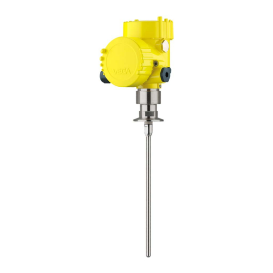
Tdr sensor for continuous level and
interface measurement of liquids.
four-wire modbus
converter version in second chamber
polished rod probe
Hide thumbs
Also See for VEGAFLEX 83:
- Operating instructions manual (96 pages) ,
- Operating instruction (92 pages) ,
- Quick setup manual (20 pages)
Table of Contents
Advertisement
Quick Links
Download this manual
See also:
Operating Instructions
Advertisement
Table of Contents

Related Manuals for Vega VEGAFLEX 83


Summary of Contents for Vega VEGAFLEX 83
-
Page 1: Operating Instructions
Operating Instructions TDR sensor for continuous level and interface measurement of liquids VEGAFLEX 83 Four-wire Modbus Converter version in second chamber Polished rod probe Document ID: 41843... -
Page 2: Table Of Contents
Set instrument address ....................53 Set up with the quick setup ..................... 54 Saving the parameter adjustment data ................55 Diagnostics and servicing Maintenance ........................56 Diagnosis memory ......................56 Status messages ......................57 Rectify faults ........................61 VEGAFLEX 83 • Four-wire Modbus... - Page 3 10.8 Industrial property rights ....................96 10.9 Trademark ........................96 Safety instructions for Ex areas Take note of the Ex specific safety instructions for Ex applications. These instructions are attached as documents to each instrument with Ex approval and are part of the operating instructions manual. Editing status: 2016-04-13 VEGAFLEX 83 • Four-wire Modbus...
-
Page 4: About This Document
Action This arrow indicates a single action. Sequence of actions Numbers set in front indicate successive steps in a procedure. Battery disposal This symbol indicates special information about the disposal of bat- teries and accumulators. VEGAFLEX 83 • Four-wire Modbus... -
Page 5: For Your Safety
During work on and with the device the required personal protective equipment must always be worn. Appropriate use VEGAFLEX 83 is a sensor for continuous level measurement. You can find detailed information about the area of application in chapter "Product description". Operational reliability is ensured only if the instrument is properly used according to the specifications in the operating instructions manual as well as possible supplementary instructions. -
Page 6: Namur Recommendations
That is why we have introduced an environment management system with the goal of continuously improving company environmental pro- tection. The environment management system is certified according to DIN EN ISO 14001. Please help us fulfil this obligation by observing the environmental instructions in this manual: • Chapter "Packaging, transport and storage" • Chapter "Disposal" VEGAFLEX 83 • Four-wire Modbus... -
Page 7: Product Description
Test certificate (PDF) - optional Go to www.vega.com "VEGA Tools" and "Instrument search". Enter the serial number. Alternatively, you can access the data via your smartphone: • Download the smartphone app "VEGA Tools" from the "Apple App Store" or the "Google Play Store" VEGAFLEX 83 • Four-wire Modbus... -
Page 8: Principle Of Operation
– If necessary, further certificates Principle of operation Application area The VEGAFLEX 83 is a level sensor with polished rod probe for continuous level or interface measurement, particularly suitable for applications in the food processing and pharmaceutical industry. VEGAFLEX 83 • Four-wire Modbus... - Page 9 Functional principle - in- High frequency microwave impulses are guided along a steel cable or terface measurement rod. Upon reaching the product surface, a part of the microwave im- pulses is reflected. The other part passes through the upper product and is reflected by the interface. The running times to the two product layers are processed by the instrument. VEGAFLEX 83 • Four-wire Modbus...
- Page 10 Example: upper medium dielectric constant 2, lower medium at least dielectric constant 12. Gas phase (L3) • Air or gas mixture • Gas phase - dependent on the application, gas phase does not always exist (d2 = 0) VEGAFLEX 83 • Four-wire Modbus...
-
Page 11: Packaging, Transport And Storage
The interface adapter VEGACONNECT enables the connection of communication-capable instruments to the USB interface of a PC. For parameter adjustment of these instruments, the adjustment software PACTware with VEGA-DTM is required. You can find further information in the operating instructions "Interface adapter VEGACONNECT" (Document-ID 32628). VEGAFLEX 83 • Four-wire Modbus... - Page 12 3 Product description The VEGADIS 81 is an external display and adjustment unit for VEGA VEGADIS 81 plics sensors. ® For sensors with double chamber housing the interface adapter "DISADAPT" is also required for VEGADIS 81. You can find further information in the operating instructions "VE- GADIS 81" (Document-ID 43814).
- Page 13 10 m (147 ft) to the sensor by using a connection cable. You can find additional information in the operating instructions manual "External housing" (Document-ID 46802). Centering If you mount the VEGAFLEX 83 in a bypass tube or standpipe, you have to avoid contact to the bypass tube by using a spacer at the probe end. You can find additional information in the operating instructions manual "Centering".
-
Page 14: Mounting
"Technical data" as well as on the type label. Mounting instructions Installation position Mount VEGAFLEX 83 in such a way that the distance to vessel instal- lations or to the vessel wall is at least 300 mm (12 in). In non-metallic VEGAFLEX 83 • Four-wire Modbus... - Page 15 The guided microwave principle requires a metallic surface on the process fitting. Therefore, in plastic vessels, etc., use an instru- ment version with flange (from DN 50) or place a metal sheet (ø > 200 mm/8 in) beneath the process fitting when screwing it in. Make sure that the plate has direct contact with the process fitting. When installing rod or cable probes in vessels without metal walls, e.g. in plastic vessels, the measured value can be influenced by strong electromagnetic fields (emitted interference according to EN 61326: class A). In this case, use a probe with coaxial version. VEGAFLEX 83 • Four-wire Modbus...
- Page 16 In such cases, always carry out a false signal suppression after instal- lation. You can find further information under "Setup procedure". DN25 ... DN150 ≤ 150 mm ( 5.91") > DN150 ... DN200 ≤ 100 mm ( 3.94") Fig. 7: Mounting socket When welding the socket, make sure that the socket is flush with the vessel top. VEGAFLEX 83 • Four-wire Modbus...
- Page 17 - measurement in these areas is not possible (dead band). The length of the cable can be used all the way to the end only when measuring conductive VEGAFLEX 83 • Four-wire Modbus...
- Page 18 For this, use an additional plastic sleeve (PTFE, PPS, PEEK etc.), to protect the probe against damages. Keep in mind that below the fastening, a measurement is not possible. Fig. 10: Fasten the probe Measuring probe Retaining sleeve 3 Plastic sleeve (PTFE, PPS, PEEK etc.) VEGAFLEX 83 • Four-wire Modbus...
- Page 19 Screw the enclosed lid with slotted nut onto the instrument side of the process fitting and tighten the nut with a torque of 20 Nm. Make sure that no liquid or contamination penetrates into the housing or the process side. After autoclaving, screw the lid off again and place the housing verti- cally on the side of the process fitting. Tighten the slotted nut with a torque of 20 Nm. VEGAFLEX 83 • Four-wire Modbus...
- Page 20 ø w ø w DIN DN25 DN32 DN40 / 1" 1 1/2" ø 50,5 DIN DN50 / 2" ø 64 DIN DN65 / 3" ø 91 Fig. 11: Autoclaved version 1 Groove nut 2 Process fitting 3 Cover with groove nut VEGAFLEX 83 • Four-wire Modbus...
-
Page 21: Connecting To Power Supply And Bus System
Max. torque for all housings, see chapter "Technical data". Cable screening and In systems with potential equalisation, connect the cable screen grounding directly to ground potential at the power supply unit, in the connection VEGAFLEX 83 • Four-wire Modbus... -
Page 22: Connection
3. Remove approx. 10 cm (4 in) of the cable mantle (signal output), strip approx. 1 cm (0.4 in) insulation from the ends of the indi- vidual wires 4. Insert the cable into the sensor through the cable entry VEGAFLEX 83 • Four-wire Modbus... - Page 23 The terminal blocks are pluggable and can be removed from the housing insert. To do this, lift the terminal block with a small screwdriv- er and pull it out. When inserting the terminal block again, you should hear it snap in. VEGAFLEX 83 • Four-wire Modbus...
-
Page 24: Wiring Plan
Information: The connection of an external display and adjustment unit is not pos- sible with this double chamber housing. Terminal compartment MODBUS power supply off on Fig. 15: Terminal compartment 1 USB interface 2 Slide switch for integrated termination resistor (120 Ω) Modbus signal Voltage supply VEGAFLEX 83 • Four-wire Modbus... -
Page 25: Double Chamber Housing With Disadapt
Fig. 17: View to the plug connector M12 x 1 Pin 1 Pin 2 Pin 3 Pin 4 Contact pin Colour connection ca- Terminal, electronics ble in the sensor module Pin 1 Brown Pin 2 White Pin 3 Blue Pin 4 Black VEGAFLEX 83 • Four-wire Modbus... -
Page 26: Supplementary Electronics
Voltage supply You can find detailed information on connection in the supplementary instructions "PLICSMOBILE GSM/GPRS radio module". Switch-on phase After VEGAFLEX 83 is connected to the bus system, the instrument carries out a self-test for approx. 30 seconds. The following steps are carried out: • Internal check of the electronics •... - Page 27 Status byte goes briefly to fault value As soon as a plausible measured value is found, it is outputted to the signal cable. The value corresponds to the actual level as well as the settings already carried out, e.g. factory settings. VEGAFLEX 83 • Four-wire Modbus...
-
Page 28: Set Up The Sensor With The Display And Adjustment Module
The display and adjustment module is powered by the sensor, an ad- ditional connection is not necessary. Fig. 20: Insertion of the display and adjustment module Note: If you intend to retrofit the instrument with a display and adjustment module for continuous measured value indication, a higher lid with an inspection glass is required. VEGAFLEX 83 • Four-wire Modbus... -
Page 29: Adjustment System
5 s, the display returns to the main menu. The menu language is then switched over to "English". Approx. 60 minutes after the last pressing of a key, an automatic reset to measured value indication is triggered. Any values not confirmed with [OK] will not be saved. VEGAFLEX 83 • Four-wire Modbus... -
Page 30: Parameter Adjustment - Quick Setup
6 Set up the sensor with the display and adjustment module After switching on, the VEGAFLEX 83 carries out a short self-test Switch-on phase where the device software is checked. The output signal transmits a fault signal during the switch-on phase. - Page 31 "->" key you jump to the next position. You can enter names with max. 19 characters. The character set comprises: • Capital letters from A … Z • Numbers from 0 … 9 • Special characters + - / _ blanks VEGAFLEX 83 • Four-wire Modbus...
- Page 32 Setup - Application - Me- In this menu item, you can define the type of medium (product). dium, dielectric constant This menu item is only available if you have selected level measure- ment under the menu item "Application". VEGAFLEX 83 • Four-wire Modbus...
- Page 33 Setup - Max. adjustment In this menu item you can enter the max. adjustment for the level. With Level interface measurement this is the maximum total level. Adjust the requested percentage value with [+] and store with [OK]. VEGAFLEX 83 • Four-wire Modbus...
- Page 34 You can accept the settings of the level measurement also for the interface measurement. If you select "Yes", the current setting will be displayed. If you have selected "No", you can enter the adjustment for the inter- face separately. Enter the requested percentage value. VEGAFLEX 83 • Four-wire Modbus...
- Page 35 By activating the appropriate curve, the volume per- centage of the vessel is displayed correctly. If the volume should not be displayed in percent but e.g. in l or kg, a scaling can be also set in the menu item "Display". VEGAFLEX 83 • Four-wire Modbus...
- Page 36 If the socket is lower than the up- per edge of the vessel, this value can also be negative. Fig. 22: Vessel height and socket correction value D Vessel height +h Positive socket correction value -h Negative socket correction value VEGAFLEX 83 • Four-wire Modbus...
- Page 37 Proceed as follows: Enter the actual distance from the sensor to the product surface. All interfering signals in this section are detected by the sensor and stored. VEGAFLEX 83 • Four-wire Modbus...
- Page 38 In the main menu point "Display", the individual submenu points should be selected subsequently and provided with the correct parameters to ensure the optimum adjustment of the display options. The procedure is described in the following. VEGAFLEX 83 • Four-wire Modbus...
- Page 39 The function depends on the strength of the supply voltage, see "Technical data". In delivery status, the lighting is switched on. Diagnostics - Device In this menu item, the device status is displayed. status VEGAFLEX 83 • Four-wire Modbus...
- Page 40 Diagnostics - Peak values Additional sensor. The values are displayed in the menu item "Peak values Ad- ditional". This menu item displays the peak values of the electronics tempera- ture as well as the dielectric constant. VEGAFLEX 83 • Four-wire Modbus...
- Page 41 Select the requested simulation variable and set the requested value. Caution: During simulation, the simulated value is outputted as 4 … 20 mA cur- rent value and digital HART signal. Push the [ESC] key to deactivate the simulation. VEGAFLEX 83 • Four-wire Modbus...
- Page 42 In this menu item, the internal clock of the sensor is adjusted. Date/Time Additional adjustments With a reset, certain parameter adjustments carried out by the user - Reset are reset. The following reset functions are available: VEGAFLEX 83 • Four-wire Modbus...
- Page 43 Min. adjustment - Interface Min. adjustment - Interface Distance: Probe length - take dead band into account Integration time - Level 0.0 s Integration time - Interface 0.0 s Linearization type Linear Linearization - Socket correction 0 mm Linearization - Vessel height Probe length VEGAFLEX 83 • Four-wire Modbus...
- Page 44 Menu item Default value Modified value Language Order-specific Displayed value 1 Filling height Level Displayed value 2 Electronics temperature Backlight Switched on Diagnostics Menu item Default value Modified value Status signals - Function control Switched on Status signals - Out of specification Switched off VEGAFLEX 83 • Four-wire Modbus...
- Page 45 From there, they can be written into one or more sen- sors or kept as backup for a possible electronics exchange. VEGAFLEX 83 • Four-wire Modbus...
- Page 46 You can accept the scaling of the level measurement also for the interface measurement. If you select "Yes", the current setting is displayed. If you have selected "No", you can enter the scaling for the interface separately. VEGAFLEX 83 • Four-wire Modbus...
- Page 47 (Multidrop operation). An address between 0 and 63 must be assigned to each sensor. If you select the function "Analogue current output" and also enter an address number, you can output a 4 … 20 mA signal in Multidrop mode. VEGAFLEX 83 • Four-wire Modbus...
-
Page 48: Saving The Parameter Adjustment Data
Saving the parameter adjustment data Backup on paper We recommended noting the adjusted data, e.g. in this operating instructions manual, and archiving them afterwards. They are thus available for multiple use or service purposes. VEGAFLEX 83 • Four-wire Modbus... - Page 49 If it is necessary to exchange a sensor, the display and adjustment module is inserted into the replacement instrument and the data are likewise written into the sensor via the menu item "Copy sensor data". VEGAFLEX 83 • Four-wire Modbus...
-
Page 50: Setting Up Sensor And Modbus Interface With Pactware
1 USB cable to the PC 2 Interface adapter VEGACONNECT Sensor To the Modbus electron- Connection of the PC to the Modbus electronics is carried out via a USB cable. Scope of the parameter adjustment: • Sensor electronics • Modbus electronics VEGAFLEX 83 • Four-wire Modbus... -
Page 51: Parameter Adjustment With Pactware
For parameter adjustment of the sensor via a Windows PC, the con- Prerequisites figuration software PACTware and a suitable instrument driver (DTM) according to FDT standard are required. The up-to-date PACTware version as well as all available DTMs are compiled in a DTM Collec- VEGAFLEX 83 • Four-wire Modbus... - Page 52 The standard version is available as a download under www.vega.com/downloads and "Software". The full version is avail- able on CD from the agency serving you. VEGAFLEX 83 • Four-wire Modbus...
-
Page 53: Set Instrument Address
7 Setting up sensor and Modbus interface with PACTware Set instrument address The VEGAFLEX 83 requires an address for participating as a Slave in the Modbus communication. The addess setting is carried out via a PC with PACTware/DTM or Modbus RTU. -
Page 54: Set Up With The Quick Setup
2 Extended adjustment Maintenance Quick setup With quick setup you can carry out the parameter adjustment of VEGAFLEX 83 for your application in just a few simple steps. The assistant-driven adjustment includes the basic settings for simple, reliable setup and commissioning. Information: If the function is inactive, then possibly no instrument is connected. -
Page 55: Saving The Parameter Adjustment Data
Click to the button "Quick setup", to start the assistant-driven adjust- Start quick setup ment for a simplified and reliable setup. Saving the parameter adjustment data We recommend documenting or saving the parameter adjustment data via PACTware. That way the data are available for multiple use or service purposes. VEGAFLEX 83 • Four-wire Modbus... -
Page 56: Diagnostics And Servicing
Echo curve of the setup: This is used as reference echo curve for the measurement conditions during setup. Changes in the measure- ment conditions during operation or buildup on the sensor can thus be recognized. The echo curve of the setup is stored via: • PC with PACTware/DTM VEGAFLEX 83 • Four-wire Modbus... -
Page 57: Status Messages
This status message is inactive by default. It can be activated by the user via PACTware/DTM or EDD. Out of specification: The measured value is unstable because the instrument specification is exceeded (e.g. electronics temperature). This status message is inactive by default. It can be activated by the user via PACTware/DTM or EDD. Maintenance: Due to external influences, the instrument function is limited. The measurement is affected, but the measured value is VEGAFLEX 83 • Four-wire Modbus... - Page 58 F041 – Cable probe broken or – Check probe and Bit 13 rod probe defective exchange, if neces- Probe loss sary F080 – General software error – Briefly separate oper- Bit 5 ating voltage General software error VEGAFLEX 83 • Four-wire Modbus...
- Page 59 – Check operating Bit 14 voltage voltage Imper- – Check connection missible cables operating voltage F267 – Sensor cannot start – Exchanging the elec- tronics No execut- – Send instrument for able sensor repair software VEGAFLEX 83 • Four-wire Modbus...
- Page 60 – With the reset to delivery – Repeat reset Bit 0 of Byte 14 … 24 status, the data could not be – Load XML file with sensor Error in the de- restored data into the sensor livery status VEGAFLEX 83 • Four-wire Modbus...
-
Page 61: Rectify Faults
Evaluation of fault messages, for example via the display and adjustment module • Checking the output signal • Treatment of measurement errors Further comprehensive diagnostics options are available with a PC with PACTware and the suitable DTM. In many cases, the reasons can be determined in this way and faults rectified. VEGAFLEX 83 • Four-wire Modbus... - Page 62 Wherever the sensor displays a constant value, the reason could also be the fault setting of the current output to "Hold value" • If the level indication is too low, the reason could be a line resist- ance that is too high VEGAFLEX 83 • Four-wire Modbus...
- Page 63 0 m distance due to false signals in the close – Check installation conditions range. The sensor goes into – If possible, switch off the func- overfill protection mode. The time tion "Overfill protection" max. level (0 m distance) as well as the status message "Overfill protection" are output- ted. VEGAFLEX 83 • Four-wire Modbus...
-
Page 64: Exchanging The Electronics Module
24 hour service hotline Should these measures not be successful, please call in urgent cases the VEGA service hotline under the phone no. +49 1805 858550. The hotline is also available outside normal working hours, seven days a week around the clock. -
Page 65: Exchanging The Rod
3. Push the enclosed new seal ring onto the thread. 4. Screw the new rod carefully by hand onto the thread on the pro- cess fitting. 5. Exert counterforce manually and tighten the rod on the flat sur- faces with a torque of 4.5 Nm (3.32 lbf ft). Fig. 38: Exchanging the measuring rod Seal ring VEGAFLEX 83 • Four-wire Modbus... -
Page 66: Exchanging The Seal
Use special tools in order to avoid damag- ing the surface. 1. Loosen the rod by applying a fork spanner to the flat surfaces (SW 10), provide counterforce manually on the process fitting 2. Screw out the loosened measuring rod by hand 3. Push the enclosed new seal ring (9.25 x 1.78) onto the thread of the measuring rod. VEGAFLEX 83 • Four-wire Modbus... - Page 67 8 Diagnostics and servicing Fig. 39: Exchanging the measuring rod Sealing ring (9.25 x 1.78) 4. Loosen process fitting with a suitable wrench. 5. Unscrew the process fitting manually from the sensor. 6. Remove the old seal out of the process fitting. 7. Insert the attached new seal ring (15.54 x 2.62) into the process fitting. VEGAFLEX 83 • Four-wire Modbus...
-
Page 68: Software Update
4.5 Nm (3.32 lbf ft). Information: Please maintain the specified torque so that the max. tensile strength of the connection remains. Software update The following components are required to update the instrument software: • Instrument • Voltage supply • Interface adapter VEGACONNECT • PC with PACTware • Current instrument software as file VEGAFLEX 83 • Four-wire Modbus... -
Page 69: How To Proceed If A Repair Is Necessary
Clean the instrument and pack it damage-proof • Attach the completed form and, if need be, also a safety data sheet outside on the packaging • Please contact the agency serving you to get the address for the return shipment. You can find the agency on our home page www.vega.com. VEGAFLEX 83 • Four-wire Modbus... -
Page 70: Dismount
Pass the instrument directly on to a spe- cialised recycling company and do not use the municipal collecting points. These may be used only for privately used products according to the WEEE directive. VEGAFLEX 83 • Four-wire Modbus... -
Page 71: Supplement
Ʋ Rod: ø 8 mm (0.315 in) - polished up to 4 m (13.12 ft) - also possible for segmented rods Ʋ Trimming accuracy - rod ±1 mm + 0.05 % of the rod length All wetted parts VEGAFLEX 83 • Four-wire Modbus... - Page 72 ø 1 m (3.281 ft), centric installation, process fitting flush with the vessel ceiling Ʋ Medium Water/Oil (dielectric constant ~2.0) Ʋ Installation Probe end does not touch the vessel bottom Sensor parameter adjustment No gating out of false signals carried out With interface measurement = 2.0 VEGAFLEX 83 • Four-wire Modbus...
- Page 73 Lower dead band (see following diagrams - grey section) Typical deviation - Interface measure- ± 5 mm (0.197 in) ment Typical deviation - Total level interface See following diagrams measurement Typical deviation - Level measurement See following diagrams 3)4) Depending on the installation conditions, deviations can occur which can be rectified by adapting the adjust- ment or changing the measured value offset in the DTM service mode The dead bands can be optimized via a false signal suppression. VEGAFLEX 83 • Four-wire Modbus...
- Page 74 Temperature drift - Digital output ±3 mm/10 K relating to the max. measuring range or max. 10 mm (0.394 in) Additional deviation through electromag- < ±10 mm (< ±0.394 in) netic interference acc. to EN 61326 VEGAFLEX 83 • Four-wire Modbus...
-
Page 75: Ambient Conditions
Process temperature (Clamp or flange temperature) Ʋ FFKM (Kalrez 6621) -20 … +150 °C (-4 … +302 °F) Time span after a sudden measuring distance change by max. 0.5 m in liquid applications, max 2 m with bulk solids applications, until the output signal has taken for the first time 90 % of the final value (IEC 61298-2). VEGAFLEX 83 • Four-wire Modbus... - Page 76 Ʋ Massive wire, stranded wire 0.2 … 2.5 mm² (AWG 24 … 14) Ʋ Stranded wire with end sleeve 0.2 … 1.5 mm² (AWG 24 … 16) Display and adjustment module Display element Display with backlight VEGAFLEX 83 • Four-wire Modbus...
- Page 77 IP 66/IP 68 (0.2 bar), NEMA Type 6P housing - investment casting, stain- less steel housing - electro-polished Protection rating (IEC 61010-1) Approvals Instruments with approvals can have different technical specifications depending on the version. The prerequisites for maintaining the protection rating are a suitable cable as well as correct mounting. VEGAFLEX 83 • Four-wire Modbus...
-
Page 78: Basics Modbus
Fig. 45: Bus architecture Modbus Connection resistor Bus participant Voltage supply Protocol description The VEGAFLEX 83 is suitable for connection to the following RTUs with Modbus RTU or ASCII protocol. Protocol ABB Totalflow Modbus RTU, ASCII Bristol ControlWaveMicro Modbus RTU, ASCII VEGAFLEX 83 • Four-wire Modbus... -
Page 79: Modbus Register
(4 bytes) according to IEEE 754 are transmitted with individually selectable order of the data bytes (byte transmission order). This "Byte transmission order" is determined in the parameter "Format Code". Hence the RTU knows the registers of the VEGAFLEX 83 which must be contacted for the variables and status information. - Page 80 See Register 100 1414 Secondary Variable in Byte Order CDAB Status 1424 DWord See Register 100 1426 Third Variable in Byte Order CDAB Status 1436 DWord See Register 100 1438 Quarternary Variable in Byte Order CDAB VEGAFLEX 83 • Four-wire Modbus...
- Page 81 Unit Codes for Register 104, 108, 112, 116 Unit Code Measurement Unit Degree Celsius Degree Fahrenheit US Gallon Liters Imperial Gallons Cubic Meters Feet Meters Barrels Inches Centimeters Millimeters Cubic Yards Cubic Feet Cubic Inches VEGAFLEX 83 • Four-wire Modbus...
-
Page 82: Modbus Rtu Commands
FC6 Write Single Register With this function code an individual holding register can be written. Request: Parameter Length Code/Data Function Code 1 Byte 0x06 Start Address 2 Bytes 0x0000 to 0xFFFF Number of Registers 2 Bytes Data VEGAFLEX 83 • Four-wire Modbus... - Page 83 Request: Parameter Length Code/Data Function Code 1 Byte 0x10 Start Address 2 Bytes 0x0000 to 0xFFFF Register Value 2 Bytes 0x0001 to 0x007B Byte Number 1 Byte Register Value N*2 Bytes Data VEGAFLEX 83 • Four-wire Modbus...
- Page 84 0x01 to 0x04 Confirmity Level 1 Byte 0x01, 0x02, 0x03, 0x81, 0x82, 0x83 More follows 1 Byte 00/FF Next Object ID 1 Byte Object ID number Number of Objects 1 Byte List of Object ID 1 Byte VEGAFLEX 83 • Four-wire Modbus...
-
Page 85: Levelmaster Commands
List of Object value 1 Byte Depending on the Object ID 10.5 Levelmaster commands The VEGAFLEX 83 is also suitable for connection to the following RTUs with Levelmaster protocol. The Levelmaster protocol is often called "Siemens" "Tank protocol". Protocol ABB Totalflow Levelmaster... - Page 86 6 characters ASCII UuuNnn Response: Parameter Length Code/Data Assign Unit Number 6 characters ASCII UuuNOK uu = new Address Set number of Floats Request: Parameter Length Code/Data Set number of Floats 5 characters ASCII UuuFn VEGAFLEX 83 • Four-wire Modbus...
- Page 87 Parameter Length Code/Data Set Receive to Transmit Delay 4 characters ASCII UuuF Response: Parameter Length Code/Data Set Receive to Transmit 5 characters ASCII UuuFn Delay n = number of measurement values (0, 1 or 2) VEGAFLEX 83 • Four-wire Modbus...
-
Page 88: Configuration Of Typical Modbus Hosts
Error While Storing Data in EEPROM FR-Error Erorr in Frame (too short, too long, wrong data) LV-Error Value out of limits 10.6 Configuration of typical Modbus hosts Fisher ROC 809 Wiring plan (Rx/Tx -) (Rx/Tx +) +30 Vdc Fig. 46: Connection of VEGAFLEX 83 to RTU Fisher ROC 809 VEGAFLEX 83 RTU Fisher ROC 809 Voltage supply VEGAFLEX 83 • Four-wire Modbus... - Page 89 Input Register Base Number The basic number of the input registers is always added to the input register address of VEGAFLEX Address 1303 must hence be entered as register address for 1302 for RTU ABB Total Flow. VEGAFLEX 83 • Four-wire Modbus...
- Page 90 The basic number of the input registers is always added to the input register address of VEGAFLEX For that reason, address 1300 must be entered as register address for 1300 for the RTU Thermo Electron Autopilot. VEGAFLEX 83 • Four-wire Modbus...
- Page 91 Input Register Base Number The basic number of the input registers is always added to the input register address of VEGAFLEX Address 1303 must hence be entered as register address for 1302 for RTU Bristol ControlWave Micro. VEGAFLEX 83 • Four-wire Modbus...
-
Page 92: Dimensions
Address 31303 must hence be entered as register address for 1302 for RTU ScadaPack. 10.7 Dimensions The following dimensional drawings represent only an extract of all possible versions. Detailed dimensional drawings can be downloaded at www.vega.com/downloads under "Drawings". VEGAFLEX 83 • Four-wire Modbus... - Page 93 (3.31") ø 79 mm (3.31") (3.11") M16x1,5 M16x1,5 M20x1,5/ M20x1,5/ ½ NPT ½ NPT Fig. 51: Dimensions of housing - with integrated display and adjustment module the housing is 9 mm/0.35 inches higher Plastic housing Aluminium/Stainless steel housing VEGAFLEX 83, rod version ø 8 mm (0.315 in), polished ø 8 mm (0.32") Fig. 52: VEGAFLEX 83, rod version ø 8 mm (0.315 in), polished Sensor length, see chapter "Technical data" VEGAFLEX 83 • Four-wire Modbus...
- Page 94 10 Supplement VEGAFLEX 83, rod version ø 8 mm (0.315 in), polished - autoclaved version ø 54 mm (2.13") ø w ø w DIN DN25 DN32 DN40 / 1" 1 1/2" ø 50,5 DIN DN50 / 2" ø 64 DIN DN65 / 3"...
- Page 95 10 Supplement Extension components - rod extension ø 8 mm (0.315 in), polished SW 10 ø8 mm (0.31") Fig. 54: Extension rods with ø 8 mm (0.315 in) 1 Version with threaded fitting 2 Version with flange connection A Basic extension rod with ø 8 mm (0.315 in) B Extension rod with ø 8 mm (0.315 in) C End rod with ø 8 mm (0.315 in) Length (order length) VEGAFLEX 83 • Four-wire Modbus...
-
Page 96: Industrial Property Rights
Les lignes de produits VEGA sont globalement protégées par des droits de propriété intellec- tuelle. Pour plus d'informations, on pourra se référer au site www.vega.com. VEGA lineas de productos están protegidas por los derechos en el campo de la propiedad indus- trial. Para mayor información revise la pagina web www.vega.com. - Page 97 False signal suppression 37 – Rod components 13 Fault rectification 61 Functional principle 9 – Spacer 13 Reset 42 Gas phase 33 Scaling measured value 46, 47 Sensor characteristics 48 HART address 47 Sensor status 39 Service hotline 64 VEGAFLEX 83 • Four-wire Modbus...
- Page 98 INDEX Simulation 41 Special parameters 48 Type label 7 Type of medium 32 Units 32 VEGAFLEX 83 • Four-wire Modbus...
- Page 99 Notes VEGAFLEX 83 • Four-wire Modbus...
- Page 100 Subject to change without prior notice © VEGA Grieshaber KG, Schiltach/Germany 2016 VEGA Grieshaber KG Phone +49 7836 50-0 Am Hohenstein 113...
Need help?
Do you have a question about the VEGAFLEX 83 and is the answer not in the manual?
Questions and answers