McCrometer Dura Mag Quick Start Installation Manual
Battery powered electromagnetic flow meter
Hide thumbs
Also See for Dura Mag:
- Installation, operation and maintenance manual (27 pages) ,
- Quick start installation manual (6 pages) ,
- Instructions (4 pages)
Table of Contents
Advertisement
Quick Links
WARNING!
!
Incorrect installation or removal of meters
can result in serious injury or death. Read
the instructions in this guide on the proper
procedures carefully.
•
Any person installing, inspecting, or maintaining
a McCrometer flowmeter should have a working
understanding of piping configurations and systems
under pressure.
•
Before adjusting or removing any meter, be certain
the system has depressurized completely.
•
Be careful when lifting meters. Meters can cause
serious injury if lifted incorrectly or dropped.
Electromagnetic Flow Meter
Quick Start Installation Guide
About This Quick Start Guide
This Quick Start Guide is a supplement to the Installation,
Operation and Maintenance manual supplied with this
meter. It is intended to be a quick reference for the basic
installation and reading of the Dura Mag.
It is designed to provide installation instructions when the
location of the sensor installation has been predetermined.
Refer to the meter manual (30122-53 Dura Mag IOM manual)
for information on these topis:
•
Preparation and planning for installation
•
Site location
•
Software configuration
•
Detailed information on external connections, external
power, outputs
For information on the data logger, refer to the manual
(30121-87 McLogger IOM), downloadable from www.
mccrometer.com).
About This Quick Start Guide. . . . . . . . . . . . . . . . .1
1.
Flow Meter Installation . . . . . . . . . . . . . . . .2
2.
Remote Mount Converter Installation . . . . . . .3
3.
Converter Wiring and Connection . . . . . . . . .4
4.
Grounding . . . . . . . . . . . . . . . . . . . . . . . .6
5.
Activating The Display . . . . . . . . . . . . . . . . .7
6.
Converter Boot. . . . . . . . . . . . . . . . . . . . . .7
7.
Converter Configuration . . . . . . . . . . . . . . .8
8.
Error Messages for Troubleshooting . . . . . . . .8
Page 1
Dura Mag
Battery Powered
30122-61 Rev. 1.4
30122-61 Rev. 1.4 | 04OCT2021
October 4, 2021
Advertisement
Table of Contents

Subscribe to Our Youtube Channel
Related Manuals for McCrometer Dura Mag


Summary of Contents for McCrometer Dura Mag
-
Page 1: Table Of Contents
Dura Mag. It is designed to provide installation instructions when the location of the sensor installation has been predetermined. Refer to the meter manual (30122-53 Dura Mag IOM manual) for information on these topis: •... -
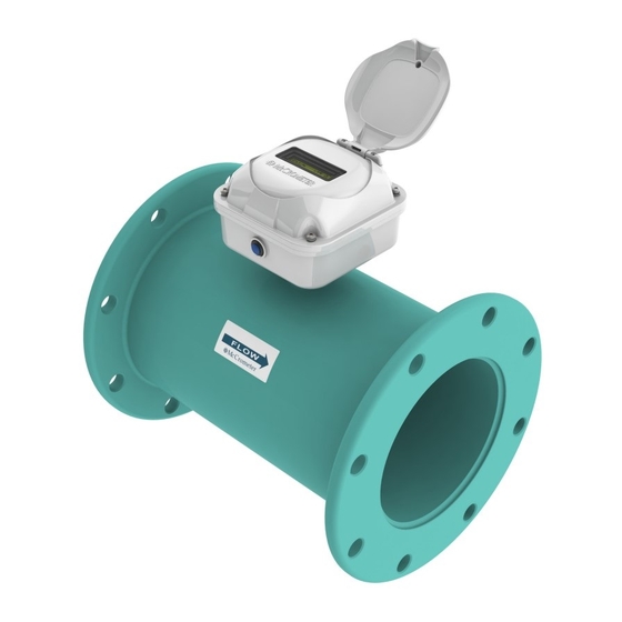
Page 2: Flow Meter Installation
Flanged Meter Installation Install the Dura Mag flow meter inline between two flanged end pipes. The flow meter may require grounding, depending on the environment they are being installed in. Refer to section 4 for a full description of grounding methods that are available. -
Page 3: Remote Mount Converter Installation
Connections to the sensor must be made with cable supplied by McCrometer specifically for that purpose. Do not substitute the supplied cable with other types of cable, even for short runs. For repairs or added lengths of cable, the entire cable between the sensor and the converter must be replaced. -
Page 4: Converter Wiring And Connection
Converter Wiring and Connection External Output Connectors The flow meter is configured at the factory for the optional outputs and requested by the customer at the time of order. The external cables attach through a permanent cable gland (standard) or through a screw locking-type waterproof connector (quick connect option). - Page 5 Green right. Green • Signals and associated wire colors in the McCrometer SmartOutput™ Black interface cable are identified together in the top row of the table above. Black •...
-
Page 6: Grounding
Grounding 1. Preferred method of grounding Dura Mag meters come standard with a set of grounding rings for use with the preferred method of grounding Dura Mag meters. This method can be used for all installations, but it is required for non-conductive or internally coated pipe. When pipes are non-conductive, such as PVC or internally coated pipe, you must substitute direct grounding with grounding rings. -
Page 7: Activating The Display
(POS) or negative (NEG), as shown at right. There is an optical sensor embedded in the display located under the McCrometer “swirl” logo at the lower left. If the display does not appear, a flashlight will provide sufficient light to bring it up. 12345... -
Page 8: Converter Configuration
Copyright © 2021 McCrometer, Inc. All printed material should not be changed or altered without permission of McCrometer. Any published pricing, technical data, and instructions are subject to change without notice. Contact your McCrometer representative for current pricing, technical data, and instructions.
Need help?
Do you have a question about the Dura Mag and is the answer not in the manual?
Questions and answers