Table of Contents
Advertisement
Quick Links
Advertisement
Chapters
Table of Contents

Related Manuals for R&S FSMR3000


Summary of Contents for R&S FSMR3000
- Page 1 ® R&S FSMR3000 Measuring Receiver User Manual (;Ý1@2) 1179011602 Version 02...
- Page 2 Rohde & Schwarz GmbH & Co. KG. Trade names are trademarks of their owners. ® 1179.0116.02 | Version 02 | R&S FSMR3000 Throughout this manual, products from Rohde & Schwarz are indicated without the ® symbol , e.g. R&S ® FSMR3000 is indicated as R&S FSMR3000.
-
Page 3: Table Of Contents
® Contents R&S FSMR3000 Contents 1 Safety and Regulatory Information............5 2 Documentation Overview..............9 3 Welcome to the R&S FSMR3............... 11 4 Getting Started..................12 5 Applications..................83 6 Measurements and Results..............92 7 Common Measurement Settings............107 8 Common Analysis and Display Functions........173 9 Data Management................ - Page 4 ® Contents R&S FSMR3000 User Manual 1179.0116.02 ─ 02...
-
Page 5: Safety And Regulatory Information
® Safety and Regulatory Information R&S FSMR3000 Safety Instructions 1 Safety and Regulatory Information The product documentation helps you use the product safely and efficiently. Follow the instructions provided here and in the following chapters. Intended use The product is intended for the development, production and verification of electronic components and devices in industrial, administrative, and laboratory environments. - Page 6 ® Safety and Regulatory Information R&S FSMR3000 Safety Instructions move or carry the product. Do not lift by the accessories mounted on the product. Accessories are not designed to carry the weight of the product. To move the product safely, you can use lifting or transporting equipment such as lift trucks and forklifts.
- Page 7 ® Safety and Regulatory Information R&S FSMR3000 Safety Instructions ● Only use intact cables and route them carefully so that they cannot be damaged. Check the power cables regularly to ensure that they are undamaged. Also ensure that nobody can trip over loose cables.
- Page 8 ® Safety and Regulatory Information R&S FSMR3000 Korea certification class B 1.2 Warning Messages in the Documentation A warning message points out a risk or danger that you need to be aware of. The sig- nal word indicates the severity of the safety hazard and how likely it will occur if you do not follow the safety precautions.
-
Page 9: Documentation Overview
® Documentation Overview R&S FSMR3000 Service Manual 2 Documentation Overview This section provides an overview of the R&S FSMR3 user documentation. Unless specified otherwise, you find the documents on the R&S FSMR3 product page at: www.rohde-schwarz.com/product/FSMR3000.html/ 2.1 Getting started manual Introduces the R&S FSMR3 and describes how to set up and start working with the... - Page 10 The brochure provides an overview of the instrument and deals with the specific char- acteristics. See www.rohde-schwarz.com/brochure-datasheet/FSMR3000/ 2.7 Release Notes and Open-Source Acknowledgment (OSA) The release notes list new features, improvements and known issues of the current firmware version, and describe the firmware installation.
-
Page 11: Welcome To The R&S Fsmr3
This user manual contains a description of the functionality that the instrument pro- vides, including remote control operation. The latest version is available for download at the product homepage (http://www.rohde-schwarz.com/product/FSMR3000.html). User Manual 1179.0116.02 ─ 02... -
Page 12: Getting Started
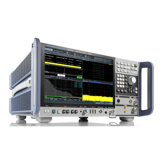
® Getting Started R&S FSMR3000 Preparing for Use 4 Getting Started 4.1 Key Features The R&S FSMR3 measuring receiver is a complete solution for calibration and perfor- mance checks of signal generators and fixed or adjustable attenuators. The R&S FSMR3 combines the functionality of multiple instruments such as a level calibra- tor, modulation analyzer and frequency counter in one. -
Page 13: Preparing For Use
® Getting Started R&S FSMR3000 Preparing for Use 4.2.1 Lifting and Carrying The carrying handles are designed to lift or carry the instrument. Do not apply exces- sive external force to the handles. "Lifting and carrying the product" on page 5. - Page 14 ® Getting Started R&S FSMR3000 Preparing for Use 4.2.4.1 Placing the Product on a Bench Top To place the product on a bench top 1. Place the product on a stable, flat and level surface. Ensure that the surface can support the weight of the product.
-
Page 15: Connecting The Ac Power
® Getting Started R&S FSMR3000 Preparing for Use To mount the R&S FSMR3 in a rack 1. Use an adapter kit to prepare the R&S FSMR3 for rack mounting. a) Order the rack adapter kit designed for the R&S FSMR3. For the order number, see the data sheet. -
Page 16: Switching The Instrument On And Off
® Getting Started R&S FSMR3000 Preparing for Use 4.2.6 Switching the Instrument On and Off Table 4-1: Overview of power states Status LED on Power key Position of main power switch gray Standby orange Ready green To switch on the R&S FSMR3 The R&S FSMR3 is off but connected to power. -
Page 17: Connecting To Lan
® Getting Started R&S FSMR3000 Preparing for Use 4.2.7 Connecting to LAN You can connect the instrument to a LAN for remote operation via a PC. Provided the network administrator has assigned you the appropriate rights and adap- ted the Windows firewall configuration, you can use the interface, for example: ●... -
Page 18: Connecting A Keyboard
® Getting Started R&S FSMR3000 Preparing for Use 4.2.8 Connecting a Keyboard The keyboard is detected automatically when it is connected. The default input lan- guage is English – US. However, you can also connect foreign language keyboards; currently the following languages are supported for the R&S FSMR3:... -
Page 19: Windows Operating System
® Getting Started R&S FSMR3000 Preparing for Use 4. Select the "Configure Monitor" tab in the "Display" dialog box. The standard Windows "Screen Resolution" dialog box is displayed. 5. Select the instrument for display: ● "Display 1": internal monitor only ●... - Page 20 ® Getting Started R&S FSMR3000 Preparing for Use You can install additional software on the instrument; however, additional software can impair instrument function. Thus, run only programs that Rohde & Schwarz has tested for compatibility with the instrument software. The following program packages have been tested: ●...
-
Page 21: Logging On
® Getting Started R&S FSMR3000 Preparing for Use The Windows taskbar also provides quick access to commonly used programs, for example Paint or WordPad. IECWIN, the auxiliary remote control tool provided free of charge and installed by Rohde & Schwarz, is also available from the taskbar or "Start"... - Page 22 ® Getting Started R&S FSMR3000 Preparing for Use Auto-login When shipped, the instrument automatically logs on the default "Instrument" user to Windows 10 using the default password. This function is active until an administrator explicitly deactivates it or changes the password.
-
Page 23: Checking The Supplied Options
® Getting Started R&S FSMR3000 Preparing for Use 4.2.12 Checking the Supplied Options The instrument can be equipped with both hardware and firmware options. To check whether the installed options correspond to the options indicated on the delivery note, proceed as follows. -
Page 24: Considerations For Test Setup
® Getting Started R&S FSMR3000 Instrument Tour 4.2.14 Considerations for Test Setup Cable selection and electromagnetic interference (EMI) Electromagnetic interference (EMI) can affect the measurement results. To suppress electromagnetic radiation during operation: ● Use high-quality shielded cables, for example, double-shielded RF and LAN cables. - Page 25 ® Getting Started R&S FSMR3000 Instrument Tour Figure 4-1: Front panel view of R&S FSMR3 1 = Touchscreen 2 = Function keys 3 = Navigation controls 4 = TRIGGER INPUT/OUTPUT 5 = RF INPUT 50 Ω 6 = POWER SENSOR connector...
- Page 26 ® Getting Started R&S FSMR3000 Instrument Tour 4.3.1.1 Power Key The power key is on the lower left corner of the front panel. It starts up and shuts down the instrument. See also "Connecting to power" on page 6. 4.3.1.2 The front panel provides three female USB connectors (USB-A) to connect devices like a keyboard or a mouse.
- Page 27 ® Getting Started R&S FSMR3000 Instrument Tour 4.3.1.4 Touchscreen All measurement results are displayed on the screen on the front panel. Additionally, the screen display provides status and setting information and allows you to switch between various measurement tasks. The screen is touch-sensitive, offering an alter- native means of user interaction for quick and easy handling of the instrument.
- Page 28 ® Getting Started R&S FSMR3000 Instrument Tour ● Changing the display ● Moving a marker ● Zooming into a diagram ● Selecting a new evaluation method ● Scrolling through a result list or table ● Saving or printing results and settings To imitate a right-click by mouse using the touchscreen, for example to open a context- sensitive menu for a specific item, press the screen for about 1 second.
- Page 29 ® Getting Started R&S FSMR3000 Instrument Tour Function key Assigned functions [Marker Function] Provides additional analysis functions of the measurement markers: Frequency counter (Sig Count) Fixed reference point for relative measurement markers (Ref Fixed) Noise marker (Noise Meas) Phase noise (Phase Noise)
- Page 30 ® Getting Started R&S FSMR3000 Instrument Tour Navigating in tables The easiest way to navigate within tables (both in result tables and configuration tables) is to scroll through the entries with your finger on the touchscreen. Rotary Knob The rotary knob has several functions: ●...
- Page 31 ® Getting Started R&S FSMR3000 Instrument Tour press [Undo] immediately afterwards, the previous status is retrieved, i.e. the zero span measurement and all settings. ● The [Redo] key repeats the previously reverted action, i.e. the most recent action is repeated.
- Page 32 ® Getting Started R&S FSMR3000 Instrument Tour Connect headphones equipped with a miniature jack plug to the AF Out female con- nector. Set the output voltage using the "Volume" control above the female connector. See also "Connecting headphones" on page 7.
- Page 33 ® Getting Started R&S FSMR3000 Instrument Tour Figure 4-3: Rear panel view of R&S FSMR3 1 = see Chapter 4.3.2.2, "Display Port and DVI", on page 34 2 = see Chapter 4.3.2.2, "Display Port and DVI", on page 34 3 = see Chapter 4.3.2.3,...
- Page 34 ® Getting Started R&S FSMR3000 Instrument Tour 1 = IF/VIDEO/DEMOD connector 2 = TRIGGER 3 INPUT/OUTPUT connector 3 = DIGITAL BASEBAND INPUT/OUTPUT connectors (option B17) 4 = SYNC TRIGGER OUTPUT/INPUT 5 = EXT GEN CONTROL interface 6 = AUX PORT...
-
Page 35: Lan
® Getting Started R&S FSMR3000 Instrument Tour 4.3.2.3 The R&S FSMR3 is equipped with a 1 GBit Ethernet IEEE 802.3u network interface with Auto-MDI(X) functionality. The assignment of the RJ-45 connector supports twis- ted-pair category 5 UTP/STP cables in a star configuration (UTP stands for unshielded twisted pair, and STP for shielded twisted pair). -
Page 36: Ref Input / Ref Output
® Getting Started R&S FSMR3000 Instrument Tour 4.3.2.8 REF Input / REF Output The REF Input connectors are used to provide an external reference signal to the R&S FSMR3. The REF Output connectors can be used to provide an external reference signal (or the optional OCXO reference signal) from the R&S FSMR3 to other devices that are... -
Page 37: Aux. Control
® Getting Started R&S FSMR3000 Instrument Tour 4.3.2.12 Aux. Control A 9-pole SUB-D male connector used as input for low-voltage TTL control signals (max. 5 V) from a controlling external device, such as an external generator. This con- nector is provided by the "Additional Interfaces" option R&S FSMR3-B5. - Page 38 ® Getting Started R&S FSMR3000 Trying Out the Instrument 4.4 Trying Out the Instrument This chapter introduces the most important functions and settings of the R&S FSMR3 step by step. The complete description of the functionality and its usage is given in the R&S FSMR3 User Manual.
- Page 39 ® Getting Started R&S FSMR3000 Trying Out the Instrument Figure 4-5: Calibration signal as RF input Instrument warmup time Note that the instrument requires an initial warmup time after switching it on. A mes- sage in the status bar ("Instrument warming up...") indicates that the operating temper- ature has not yet been reached.
- Page 40 ® Getting Started R&S FSMR3000 Trying Out the Instrument Figure 4-6: Calibration signal with optimized display settings 4.4.2 Displaying a Spectrogram In addition to the standard "level versus frequency" spectrum display, the R&S FSMR3 also provides a spectrogram display of the measured data. A spectrogram shows how the spectral density of a signal varies over time.
- Page 41 ® Getting Started R&S FSMR3000 Trying Out the Instrument Figure 4-7: Adding a Spectrogram to the display Drop the icon. 4. Close the SmartGrid mode by tapping the "Close" icon at the top right corner of the toolbar. You see the spectrogram compared to the standard spectrum display. Since the calibration signal does not change over time, the color of the frequency levels does not change over time, i.e.
- Page 42 ® Getting Started R&S FSMR3000 Trying Out the Instrument Figure 4-8: Spectrogram of the calibration signal 4.4.3 Activating Additional Measurement Channels The R&S FSMR3 features multiple measurement channels, i.e. you can define several measurement configurations in parallel and then switch between the channels auto- matically to perform the measurements sequentially.
- Page 43 ® Getting Started R&S FSMR3000 Trying Out the Instrument Figure 4-9: Adding a new measurement channel 3. Change the frequency range for this spectrum display: In the "Frequency" dialog box, set the center frequency to 500 MHz and the span to 1 GHz.
- Page 44 ® Getting Started R&S FSMR3000 Trying Out the Instrument As the calibration signal does not vary over time, the level versus time diagram dis- plays a straight line. Figure 4-11: Time domain display of the calibration signal 5. Create a new channel for I/Q analysis: a) Press the [Mode] key.
- Page 45 ® Getting Started R&S FSMR3000 Trying Out the Instrument e) Close the SmartGrid mode. The "IQ Analyzer" channel displays the real and imaginary signal parts in separate windows. To display the MultiView tab An overview of all active channels is provided in the "MultiView" tab. This tab is always displayed and cannot be closed.
- Page 46 ® Getting Started R&S FSMR3000 Trying Out the Instrument Figure 4-14: "MultiView" tab with active Sequencer Figure 4-14, the "Spectrum 2" measurement is currently active (indicated by the "channel active" icon in the tab label). 3. Stop the Sequencer by tapping the "Sequencer" softkey again.
- Page 47 ® Getting Started R&S FSMR3000 Trying Out the Instrument 6. Now you can move the marker by tapping and dragging it to a different position. The current position is indicated by a dotted blue line. Notice how the position and value change in the marker area of the diagram.
- Page 48 ® Getting Started R&S FSMR3000 Trying Out the Instrument 2. Press the "RUN SINGLE" key on the front panel to perform a single sweep for which we will determine the peaks. Tap the "SmartGrid" icon in the toolbar to activate SmartGrid mode.
- Page 49 ® Getting Started R&S FSMR3000 Trying Out the Instrument Tap the "Multiple Zoom" icon in the toolbar. The icon is highlighted orange to indicate that multiple zoom mode is active. 2. Tap the diagram near the first peak and drag your finger to the opposite corner of the zoom area.
- Page 50 ® Getting Started R&S FSMR3000 Trying Out the Instrument Figure 4-18: Zoomed peak with increased number of sweep points Note that the trace becomes much more precise. Tap the "Multiple Zoom" icon in the toolbar again and define a zoom area around markers M4, M5 and M6.
- Page 51 ® Getting Started R&S FSMR3000 Trying Out the Instrument Figure 4-20: Enlarged zoom window 4.4.8 Zooming into the Display Permanently The zoomed results from Chapter 4.4.7, "Zooming into the Display", on page 48 were only graphical changes to the display. Now we would like to change the measurement settings such that the zoomed result is maintained permanently.
- Page 52 ® Getting Started R&S FSMR3000 Trying Out the Instrument 3. Select the (graphical) zoom icon on the toolbar. Any subsequent touch gestures define the zoom area for the zoom display. 4. Place two fingers on the diagram, to the left and right of the marker, and stretch them apart.
- Page 53 ® Getting Started R&S FSMR3000 Trying Out the Instrument 6. Tap the "Measurement Zoom" icon on the toolbar for a second or so. A context menu with further options is displayed. 7. Select "Adapt Hardware to Zoom (selected diagram)". The span of the measurement is changed, and due to the automatic coupling of the span to the sweep time, RBW and VBW, those values are also changed.
- Page 54 ® Getting Started R&S FSMR3000 Trying Out the Instrument 4.4.9 Saving Settings To restore the results of our measurements later, we will store the instrument settings to a file. To save the instrument settings to a file Tap the "Save" icon in the toolbar.
- Page 55 ® Getting Started R&S FSMR3000 Trying Out the Instrument 4. Tap the "Save" button. The file MyMultiViewSetup.dfl is stored in the default directory C:/R_S/ instr/user. To load stored instrument settings You can restore the settings to the instrument at any time using the settings file.
- Page 56 ® Getting Started R&S FSMR3000 Operating the Instrument The screenshot is stored to MyMultiViewDisplay.png. Figure 4-22: Screenshot of the current display 4.5 Operating the Instrument This chapter provides an overview on how to work with the R&S FSMR3. Remote control In addition to working with the R&S FSMR3 interactively, located directly at the instru-...
- Page 57 ® Getting Started R&S FSMR3000 Operating the Instrument ● Touchscreen Gestures.................... 71 ● Displaying Results....................74 ● Getting Help......................81 4.5.1 Understanding the Display Information The following figure shows a measurement diagram in Spectrum mode. All different information areas are labeled. They are explained in more detail in the following sec- tions.
-
Page 58: Channel Bar
® Getting Started R&S FSMR3000 Operating the Instrument ● Channel Bar......................58 ● Window Title Bar..................... 61 ● Marker Information....................62 ● Frequency and Span Information in Diagram Footer..........63 ● Instrument and Status Information................63 ● Error Information..................... 64 4.5.1.1... - Page 59 ® Getting Started R&S FSMR3000 Operating the Instrument icon indicates that an error or warning is available for that measurement chan- nel. This is particularly useful if the MultiView tab is displayed. icon indicates the currently active channel during an automatic measurement sequence (Sequencer functionality).
- Page 60 ® Getting Started R&S FSMR3000 Operating the Instrument Common settings The channel bar above the diagram not only displays the channel-specific settings. It also displays information on instrument settings that affect the measurement results even though it is not immediately apparent from the display of the measured values.
-
Page 61: Window Title Bar
® Getting Started R&S FSMR3000 Operating the Instrument Note: Channel name restrictions. Channel names can have a maximum of 31 charac- ters, and must be compatible with the Windows conventions for file names. In particu- lar, they must not contain special characters such as ":", "*", "?". -
Page 62: Marker Information
® Getting Started R&S FSMR3000 Operating the Instrument MAX HOLD MIN HOLD AVERAGE (Lin/Log/Pwr) View VIEW (5) Smoothing factor Smth Smoothing factor, if enabled. Norm/NCor Correction data is not used. 4.5.1.3 Marker Information Marker information is provided either in the diagram grid or in a separate marker table, depending on the configuration. -
Page 63: Frequency And Span Information In Diagram Footer
® Getting Started R&S FSMR3000 Operating the Instrument MDepth AM modulation depth Third order intercept measurement 4.5.1.4 Frequency and Span Information in Diagram Footer The information in the diagram footer (beneath the diagram) depends on the current application, measurement, and result display. -
Page 64: Error Information
® Getting Started R&S FSMR3000 Operating the Instrument Error messages If errors or irregularities are detected, a keyword and an error message, if available, are displayed in the status bar. 4.5.1.6 Error Information If errors or irregularities are detected, a keyword and an error message, if available, are displayed in the status bar. - Page 65 ® Getting Started R&S FSMR3000 Operating the Instrument The measurement and instrument functions and settings can be accessed by selecting one of the following elements: ● System and function keys on the front panel of the instrument ● Softkeys on the touchscreen ●...
- Page 66 ® Getting Started R&S FSMR3000 Operating the Instrument Icon Description Measurement zoom: applies to the next display you select; Displays a dotted rectangle in the diagram that can be expanded to define the zoom area; the selected diagram is replaced by a new diagram with adapted measurement settings which dis- plays the selected extract of the trace.
- Page 67 ® Getting Started R&S FSMR3000 Operating the Instrument 4.5.2.2 Softkeys Softkeys are virtual keys provided by the software. Thus, more functions can be provi- ded than those that can be accessed directly via the function keys on the instrument. Softkeys are dynamic, i.e. depending on the selected function key, a different list of softkeys is displayed on the right side of the screen.
- Page 68 ® Getting Started R&S FSMR3000 Operating the Instrument Figure 4-24: Context menu for a result display with SCPI Recorder functions If SCPI Recorder functions are not available, for example for channel bar settings or in some applications, the context menu contains functions for the selected item. These functions correspond to the functions also provided for the item in softkey menus.
- Page 69 ® Getting Started R&S FSMR3000 Operating the Instrument The on-screen keyboard display can be switched on and off as desired using the "On- Screen Keyboard" function key beneath the screen. When you press this key, the display switches between the following options: ●...
- Page 70 ® Getting Started R&S FSMR3000 Operating the Instrument 1. Enter the parameter value using the keypad, or change the currently used parame- ter value by using the rotary knob (small steps) or the [UP] or [DOWN] keys (large steps). 2. After entering the numeric value via keypad, press the corresponding unit key.
- Page 71 ® Getting Started R&S FSMR3000 Operating the Instrument To correct an entry 1. Using the arrow keys, move the cursor to the right of the entry you want to delete. 2. Press the [BACKSPACE] key. The entry to the left of the cursor is deleted.
- Page 72 ® Getting Started R&S FSMR3000 Operating the Instrument Figure 4-26: Tapping Double-tapping Tap the screen twice, in quick succession. Double-tap a diagram or the window title bar to maximize a window in the display, or to restore the original size.
- Page 73 ® Getting Started R&S FSMR3000 Operating the Instrument Figure 4-28: Pinching Figure 4-29: Spreading Touch gestures in diagrams change measurement settings When you change the display using touch gestures, the corresponding measurement settings are adapted. This is different to selecting an area on the screen in zoom mode, where merely the resolution of the displayed trace points is changed temporarily (graphical zoom).
- Page 74 ® Getting Started R&S FSMR3000 Operating the Instrument Table 4-11: Correlation of mouse and touch actions Mouse operation Touch operation Click Double-click Double-tap Click and hold Touch and hold Right-click Touch, hold for 1 second and release Drag-&-drop (= click and hold, then drag and...
- Page 75 ® Getting Started R&S FSMR3000 Operating the Instrument Only one measurement can be performed at any time, namely the one in the currently active channel. However, in order to perform the configured measurements consecu- tively, a Sequencer function is provided.
- Page 76 ® Getting Started R&S FSMR3000 Operating the Instrument To close a measurement channel ► Select the "Close" icon on the tab of the measurement channel. The tab is closed, any running measurements are aborted, and all results for that channel are deleted.
- Page 77 ® Getting Started R&S FSMR3000 Operating the Instrument Background Information: The SmartGrid Principle SmartGrid display During any positioning action, the underlying SmartGrid is displayed. Different colors and frames indicate the possible new positions. The position in the SmartGrid where you drop the window determines its position on the screen.
- Page 78 ® Getting Started R&S FSMR3000 Operating the Instrument Figure 4-31: SmartGrid window positions 1 = Insert row above or below the existing row 2 = Create a new column in the existing row 3 = Replace a window in the existing row...
- Page 79 ® Getting Started R&S FSMR3000 Operating the Instrument 1. Activate SmartGrid mode. All evaluation methods available for the currently selected measurement are dis- played as icons in the evaluation bar. 2. Select the icon for the required evaluation method from the evaluation bar.
- Page 80 ® Getting Started R&S FSMR3000 Operating the Instrument Remote command: on page 478 / LAYout:REPLace[:WINDow] LAYout:WINDow<n>:REPLace on page 481 on page 477 LAYout:MOVE[:WINDow] 4.5.5.3 Changing the Size of Windows Each channel tab may contain several windows to evaluate the measurement results using different methods.
- Page 81 ® Getting Started R&S FSMR3000 Operating the Instrument To switch between a split and a maximized display without having to close and re-open windows, press the [SPLIT/MAXIMIZE] key on the front panel. In maximized display, the currently focused window is maximized. In split display, all active windows are dis- played.
- Page 82 ® Getting Started R&S FSMR3000 Operating the Instrument For standard Windows dialog boxes (e.g. File Properties, Print dialog etc.), no context- sensitive help is available. To display a help topic for a screen element not currently focused 1. Select the "Help pointer" icon on the toolbar.
-
Page 83: Applications
® Applications R&S FSMR3000 R&S MultiView 5 Applications The R&S FSMR3 is a dedicated Measuring Receiver whose main feature is the mea- suring receiver application. When equipped accordingly (with optional hardware or software), it is able to provide several additional applications for different analysis tasks (for example the spectrum application). -
Page 84: Am/Fm/Pm Modulation Analysis
® Applications R&S FSMR3000 Available Applications Remote command: on page 474 DISPlay:FORMat 5.2 Available Applications Depending on its outfit, the R&S FSMR3 provides one or more applications for specific measurement tasks. AM/FM/PM Modulation Analysis................... 84 Avionics.........................84 Analyzer........................84 Measuring Receiver...................... 85 Noise Figure........................85... -
Page 85: Available Applications
® Applications R&S FSMR3000 Available Applications Measuring Receiver The measuring receiver application provides measurement functions to analyze and demodulate the characteristics of a DUT. This application is used in the initial configuration. For details, refer to Chapter 6, "Measurements and Results",... -
Page 86: Spectrum Monitor
® Applications R&S FSMR3000 Selecting the Operating Mode and Applications Spectrum Monitor The spectrum monitor application provides measurement functions for basic I/Q data analysis. For details, refer to the user manual of the I/Q analyzer. Remote command: INST:SEL SMONitor, see... - Page 87 ® Applications R&S FSMR3000 Selecting the Operating Mode and Applications Switching between applications When you switch to a new application, a set of parameters is passed on from the cur- rent application to the new one: ● center frequency and frequency offset ●...
- Page 88 ® Applications R&S FSMR3000 Running a Sequence of Measurements Closing an application To close an application, simply close the corresponding tab by selecting the "x" next to the channel name. Remote command: on page 394 INSTrument:DELete 5.4 Running a Sequence of Measurements Only one measurement can be performed at any time, namely the one in the currently active channel.
- Page 89 ® Applications R&S FSMR3000 Running a Sequence of Measurements Example: Sequencer procedure Assume the following active channel definition: Tab name Application Sweep mode Sweep count Spectrum Spectrum Cont. Sweep Spectrum 2 Spectrum Single Sweep Spectrum 3 Spectrum Cont. Sweep IQ Analyzer...
- Page 90 ® Applications R&S FSMR3000 Running a Sequence of Measurements The "Single Sweep" and "Continuous Sweep" softkeys control the sweep mode for the currently selected channel only; the sweep mode only has an effect the next time the Sequencer activates that channel, and only for a channel-defined sequence. In this case, a channel in single sweep mode is swept only once by the Sequencer.
- Page 91 ® Applications R&S FSMR3000 Running a Sequence of Measurements The "Sequencer" menu is displayed. 3. Toggle the "Sequencer" softkey to "On". A continuous sequence is started immediately. 4. To change the Sequencer mode and start a new sequence immediately, select the corresponding mode softkey, or press the [Run Single] or [Run Cont] key.
-
Page 92: Measurements And Results
® Measurements and Results R&S FSMR3000 Selecting Measurements 6 Measurements and Results Access: "Overview" > "Select Measurement" Or: [MEAS] In the Measuring Receiver application, the R&S FSMR3 provides a variety of different measurement functions. ● Basic measurements - measure the RF power or tuned RF level your signal ●... - Page 93 ® Measurements and Results R&S FSMR3000 Selecting Measurements Tuned RF-Level......................93 Demodulation Measurements..................93 RF-Power........................94 Tuned RF-Level Provides functionality to perform Tuned RF-Level calibration and power measure- ments. For the configuration of TRFL measurements, see Chapter 7.7, "Tuned RF Level Set- tings",...
- Page 94 ® Measurements and Results R&S FSMR3000 Selecting Measurements For the configuration of demodulation measurements, see Chapter 7.6, "Demodula- tion", on page 156. Remote command: CONF:MEAS AM CONF:MEAS FM CONF:MEAS PM RF-Power Provides functionality to measure the absolute power and reference power of a signal using a power sensor.
-
Page 95: Am Time Domain
® Measurements and Results R&S FSMR3000 Result Displays For the configuration of RF-Power measurements, see Chapter 7.2.2, "Power Sen- sors", on page 110. Remote command: CONF:MEAS POWer 6.2 Result Displays Access: "Overview" > "Display Config" Or: [MEAS] > "Display Config"... -
Page 96: Fm Time Domain
® Measurements and Results R&S FSMR3000 Result Displays Remote command: LAY:ADD? '1',RIGH,'XTIM:AM:REL' (See on page 475) LAYout:ADD[:WINDow]? FM Time Domain Displays the frequency spectrum of the demodulated FM signal versus time. User Manual 1179.0116.02 ─ 02... -
Page 97: Pm Time Domain
® Measurements and Results R&S FSMR3000 Result Displays Remote command: LAY:ADD? '1',RIGH,'XTIM:FM' (See on page 475) LAYout:ADD[:WINDow]? PM Time Domain Displays the phase deviations of the demodulated PM signal (in rad or °) versus time. User Manual 1179.0116.02 ─ 02... -
Page 98: Am Spectrum
® Measurements and Results R&S FSMR3000 Result Displays Remote command: LAY:ADD? '1',RIGH,'XTIM:PM' (See on page 475) LAYout:ADD[:WINDow]? AM Spectrum Displays the modulation depth of the demodulated AM signal (in % or dB) versus AF span. The spectrum is calculated from the demodulated AM signal in the time domain via FFT. -
Page 99: Fm Spectrum
® Measurements and Results R&S FSMR3000 Result Displays Note: If a high pass or low pass AF filter is defined, the filter is indicated by a vertical red line in the spectrum display. Remote command: LAY:ADD? '1',RIGH,'XTIMe:AM:REL:AFSPectrum1' (see on page 475) -
Page 100: Pm Spectrum
® Measurements and Results R&S FSMR3000 Result Displays Note: If a high pass or low pass AF filter is defined, the filter is indicated by a vertical red line in the spectrum display. Remote command: LAY:ADD? '1',RIGH,'XTIMe:FM:AFSPectrum1' (see on page 475) -
Page 101: Rf Time Domain
® Measurements and Results R&S FSMR3000 Result Displays Note: If a high pass or low pass AF filter is defined, the filter is indicated by a vertical red line in the spectrum display. Remote command: LAY:ADD? '1',RIGH,'XTIMe:PM:AFSPectrum1' (see on page 475) -
Page 102: Rf Spectrum
® Measurements and Results R&S FSMR3000 Result Displays Remote command: LAY:ADD? '1',RIGH,'XTIM:AM' (see on page 475) LAYout:ADD[:WINDow]? RF Spectrum Displays the spectrum of the input signal. In contrast to the Spectrum application, the frequency values are determined using FFT from the recorded I/Q data set. -
Page 103: Result Summary
® Measurements and Results R&S FSMR3000 Result Displays Remote command: LAY:ADD? '1',RIGH,'XTIM:SPECTRUM' (see on page 475) LAYout:ADD[:WINDow]? Result Summary The result summary displays the results of the demodulation functions for all windows in a table. For each demodulation, the following information is provided:... -
Page 104: Signal Summary
® Measurements and Results R&S FSMR3000 Result Displays Table 6-1: Result summary description Label Description +Peak Positive peak (maximum) -Peak Negative peak (minimum) +/-Peak/2 Average of positive and negative peaks Root Mean Square value Root Mean Square value * √2... -
Page 105: Corr Status
® Measurements and Results R&S FSMR3000 Result Displays Remote command: LAY:ADD? '1',RIGH,XTIMe:RFPower:BARG, see LAYout:ADD[:WINDow]? on page 475 CORR Status Displays the condition of the following functions and device labels: ● Splitter ● Signal Track ● ● Cal Abs Power ●... - Page 106 ® Measurements and Results R&S FSMR3000 Result Displays Remote command: LAY:ADD? '1',RIGH, PEAK, see on page 475 LAYout:ADD[:WINDow]? Results: on page 513 CALCulate<n>:MARKer<m>:X User Manual 1179.0116.02 ─ 02...
-
Page 107: Common Measurement Settings
® Common Measurement Settings R&S FSMR3000 Configuration Overview 7 Common Measurement Settings Basic measurement settings that are common to many measurement tasks, regardless of the application or operating mode, are described here. If you are using an applica- tion other than the Measuring Receiver application, be sure to check the documenta- tion for that application. -
Page 108: Input And Frontend
® Common Measurement Settings R&S FSMR3000 Input and Frontend In particular, the "Overview" provides quick access to the following configuration dialog boxes (listed in the recommended order of processing): 1. Input Chapter 7.2, "Input and Frontend", on page 108. 2. Trigger Chapter 7.3, "Trigger... - Page 109 ® Common Measurement Settings R&S FSMR3000 Input and Frontend ● Input Source Settings....................109 ● Power Sensors...................... 110 ● Power Splitter......................119 ● Optional External Generator Control..............120 ● Amplitude Settings....................141 ● Frequency......................143 7.2.1 Input Source Settings 7.2.1.1 Radio Frequency Input Access: Overview >...
- Page 110 INPut<ip>:DPATh YIG-Preselector Enables or disables the YIG-preselector, if available on the R&S FSMR3000. Note: Note that the YIG-preselector is active only on frequencies greater than 8 GHz. Therefore, switching the YIG-preselector on or off has no effect if the frequency is below that value.
- Page 111 ® Common Measurement Settings R&S FSMR3000 Input and Frontend 7.2.2.1 Basics on Power Sensors For precise power measurement, up to 4 power sensors can be connected to the instrument via the power sensor interface (on the front panel) or the USB connectors.
- Page 112 ® Common Measurement Settings R&S FSMR3000 Input and Frontend Figure 7-2: Connecting a power sensor using the POWER SENSOR interface The R&S FSMR3 receives an external trigger signal when the defined trigger level is measured by the power sensor. Power measurement results are provided as usual.
- Page 113 ® Common Measurement Settings R&S FSMR3000 Input and Frontend Frequency Coupling....................114 Unit/Scale........................114 Meas Time/Average.....................114 Setting the Reference Level from the Measurement Meas -> Ref......115 Reference Value......................115 Use Ref Level Offset....................115 Sensor Level Offset..................... 115 Average Count (Number of Readings)................
- Page 114 ® Common Measurement Settings R&S FSMR3000 Input and Frontend Remote command: on page 411 [SENSe:]PMETer<p>[:STATe] on page 405 SYSTem:COMMunicate:RDEVice:PMETer<p>:DEFine SYSTem:COMMunicate:RDEVice:PMETer<p>:CONFigure:AUTO[:STATe] on page 404 on page 404 SYSTem:COMMunicate:RDEVice:PMETer<p>:COUNt? Zeroing Power Sensor Starts zeroing of the power sensor. Remote command: on page 406 CALibration:PMETer<p>:ZERO:AUTO ONCE...
- Page 115 ® Common Measurement Settings R&S FSMR3000 Input and Frontend Remote command: on page 409 [SENSe:]PMETer<p>:MTIMe on page 410 [SENSe:]PMETer<p>:MTIMe:AVERage[:STATe] Setting the Reference Level from the Measurement Meas -> Ref Sets the currently measured power as a reference value for the relative display. The...
- Page 116 If activated, the power sensor creates a trigger signal when a power higher than the defined "External Trigger Level" is measured. This trigger signal can be used as an external power trigger by the R&S FSMR3000. This setting is only available in conjunction with a compatible power sensor.
- Page 117 ® Common Measurement Settings R&S FSMR3000 Input and Frontend Power sensors can also be used to trigger a measurement at a specified power level, e.g. from a signal generator. This is described in "How to Configure a Power Sensor as an External (PSE) Trigger"...
- Page 118 ® Common Measurement Settings R&S FSMR3000 Input and Frontend 10. To use the power sensor as an external power trigger, select the "External Power Trigger" option and define the trigger settings. For details see "How to Configure a Power Sensor as an External (PSE) Trigger"...
- Page 119 ® Common Measurement Settings R&S FSMR3000 Input and Frontend 6. In the "Trigger And Gate" dialog box, select "Signal Source" = "PSE". The R&S FSMR3 is configured to trigger when the defined conditions for the power sensor occur. Power measurement results are provided as usual.
-
Page 120: External Generator Connections
® Common Measurement Settings R&S FSMR3000 Input and Frontend 7.2.4 Optional External Generator Control If the R&S FSMR3 optional External Generator Control is installed, you can operate various commercially available generators as an external generator with the R&S FSMR3. Thus, scalar network analysis with the R&S FSMR3 is possible. - Page 121 ® Common Measurement Settings R&S FSMR3000 Input and Frontend TTL synchronization In addition, TTL synchronization can be used with some Rohde & Schwarz generators connected via GPIB. The TTL interface is included in the AUX control connector of the External Generator Control option.
- Page 122 ® Common Measurement Settings R&S FSMR3000 Input and Frontend Signal analyzer Signal generator rear panel rear panel BNC Trigger BNC Blank Figure 7-5: TTL connection for an R&S SMA100B generator The external generator can be used to calibrate the data source by performing either transmission or reflection measurements.
- Page 123 ® Common Measurement Settings R&S FSMR3000 Input and Frontend Generated signal input In order to use the functions of the external generator, an appropriate generator must be connected and configured correctly. In particular, the generator output must be con- nected to the RF input of the R&S FSMR3.
- Page 124 ® Common Measurement Settings R&S FSMR3000 Input and Frontend Generator Model Driver file TTL sup- Generator type Model Driver file TTL sup- type port port 67 GHz SMA100B67 30 GHz SMR30B11 SMB100A 1 GHz SMB100A1 40 GHz SMR40 12 GHz...
-
Page 125: Generator Setup Files
® Common Measurement Settings R&S FSMR3000 Input and Frontend Generator Model Driver file TTL sup- Generator type Model Driver file TTL sup- type port port SMGL SMGL 2 GHz SMY02 SMGU SMGU SMHU SMHU SMIQ 2 GHz SMIQ02 2 GHz... - Page 126 ® Common Measurement Settings R&S FSMR3000 Input and Frontend Numerator Generator Analyzer Offset Deno ator Equation 7-1: Output frequency of the generator Where: = output frequency of the generator Generator = current frequency at the RF input of the R&S FSMR3...
-
Page 127: Errors
® Common Measurement Settings R&S FSMR3000 Input and Frontend ration. (Note that the frequency is defined as the unsigned value of the equation, thus a negative frequency is not possible.) Example: Example for reverse sweep = 100 MHz AnalyzerStart = 200 MHz... -
Page 128: Settings
® Common Measurement Settings R&S FSMR3000 Input and Frontend Message Description "Ext. Generator GPIB Handshake Error!" / Connection to the generator is not possible, e.g. due to a cable damage or loose connection or wrong address. "Ext. Generator TCPIP Handshake Error!" / "Ext. -
Page 129: Generators
® Common Measurement Settings R&S FSMR3000 Input and Frontend Generator Type......................129 Interface........................129 Handshake......................129 GPIB Address/TCPIP Address / Computer Name............129 Reference........................130 Edit Generator Setup File....................130 Frequency Min/ Frequency Max..................130 Level Min/ Level Max....................130 Generator Type Selects the generator type and thus defines the generator setup file to use. - Page 130 ® Common Measurement Settings R&S FSMR3000 Input and Frontend Remote command: on page 419 SYSTem:COMMunicate:GPIB:RDEVice:GENerator<gen>:ADDRess SYSTem:COMMunicate:TCPip:RDEVice:GENerator<gen>:ADDRess on page 420 Reference Selects the internal R&S FSMR3 or an external frequency reference to synchronize the R&S FSMR3 with the generator (default: internal).
- Page 131 ® Common Measurement Settings R&S FSMR3000 Input and Frontend Source State....................... 131 Source Power......................131 Source Offset......................131 Source Frequency Coupling..................131 (Manual) Source Frequency..................132 (Automatic) Source Frequency (Numerator/Denominator/Offset)....... 132 Result Frequency Start....................132 Result Frequency Stop....................132 Source State Activates or deactivates control of an external generator.
-
Page 132: Control
® Common Measurement Settings R&S FSMR3000 Input and Frontend (Manual) Source Frequency Defines the fixed frequency to be used by the generator. Remote command: on page 415 SOURce<si>:EXTernal<gen>:FREQuency (Automatic) Source Frequency (Numerator/Denominator/Offset) With automatic frequency coupling, a series of frequencies is defined (one for each sweep point), based on the current frequency at the RF input of the R&S FSMR3. - Page 133 ® Common Measurement Settings R&S FSMR3000 Input and Frontend ● How to Calibrate a Measurement Setup using an External Generator....133 ● How to Remove the Effects of a Particular Component from Measurement Results Using Calibration....................134 ● How to Compensate for Additional Gain or Attenuation after Calibration.....
- Page 134 ® Common Measurement Settings R&S FSMR3000 Input and Frontend 16. Select the "Source Calibration Type": "Transmission" to perform a calibration sweep and store a reference trace for the measurement setup. 17. Select "Source Calibration Normalize": "On". 18. Optionally, shift the reference line further down in the result display by descreasing the "Reference": "Position".
- Page 135 ® Common Measurement Settings R&S FSMR3000 Input and Frontend 5. Select the stored transducer in the list of available transducers and select the "Active" setting for it. 6. Perform any measurement with the setup that contains the calibrated component. The measurement results do not include the effects from the component.
- Page 136 ® Common Measurement Settings R&S FSMR3000 Input and Frontend Calibrating the measurement setup 1. Connect the signal generator's GPIB interface connector to the [Ext. Gen.Control GPIB] connector on the rear panel of the R&S FSMR3. 2. Connect the signal generator output to the [RF input] connector of the R&S FSMR3.
- Page 137 ® Common Measurement Settings R&S FSMR3000 Input and Frontend 13. Select "Source Calibration Normalize": "On" to set the measurement results for the current setup to 0, thus eliminating all effects from the generator, the analyzer and the connecting cables from subsequent measurements with the band elimination filter.
- Page 138 ® Common Measurement Settings R&S FSMR3000 Input and Frontend Figure 7-10: Band elimination filter results 3. Shift the reference line from the top of the diagram to the middle of the diagram by changing the position of the reference point 0.0 dB to 50 %.
- Page 139 ® Common Measurement Settings R&S FSMR3000 Input and Frontend Compensating the effects of additional attenuation after calibration After calibration, an additional attenuator is inserted between the DUT and the R&S FSMR3. This may be necessary, for example, to protect the analyzer's input con- nector.
- Page 140 ® Common Measurement Settings R&S FSMR3000 Input and Frontend Figure 7-13: Reference line with an offset of -3 dB and shifted to middle of diagram (50%) 3. After the reference trace has been shifted, you can zoom into the measured trace to determine the offsets to the reference line, which represent the effects of the band elimination filter in the measurement setup.
- Page 141 Since the hardware of the R&S FSMR3000 is adapted according to this value, it is rec- ommended that you set the reference level close above the expected maximum signal level.
- Page 142 ® Common Measurement Settings R&S FSMR3000 Input and Frontend Shifting the Display (Offset) ← Reference Level Defines an arithmetic level offset. This offset is added to the measured level. In some result displays, the scaling of the y-axis is changed accordingly.
-
Page 143: Trigger Settings
® Common Measurement Settings R&S FSMR3000 Trigger Settings Remote command: on page 433 INPut<ip>:GAIN:STATe on page 433 INPut<ip>:GAIN[:VALue] 7.2.6 Frequency Access: "Overview" > "Input/Frontend" > "Frequency" tab Center Frequency....................... 143 Center Frequency Stepsize..................143 Center Frequency Defines the center frequency of the signal in Hertz. - Page 144 ® Common Measurement Settings R&S FSMR3000 Trigger Settings 7.3.1 Trigger Source Provides functionality to set up a specific trigger source. Trigger Source......................144 └ Free Run....................... 144 └ Ext. Trigger 1/2..................... 144 └ Video......................145 └ Power...................... 145 └ Power Sensor....................145 Trigger Level.......................
- Page 145 ® Common Measurement Settings R&S FSMR3000 Trigger Settings For details, see the "Instrument Tour" chapter in the R&S FSMR3 Getting Started man- ual. "External Trigger 1" Trigger signal from the "Trigger Input / Output" connector. (front panel) "External Trigger 2"...
- Page 146 ® Common Measurement Settings R&S FSMR3000 Trigger Settings Trigger Level Defines the trigger level for the specified trigger source. For details on supported trigger levels, see the instrument data sheet. Remote command: on page 442 TRIGger[:SEQuence]:LEVel[:EXTernal<port>] Drop-Out Time Defines the time that the input signal must stay below the trigger level before triggering again.
- Page 147 R&S FSMR3000. Trigger input parameters are available in the "Trigger" dialog box. "Output" The R&S FSMR3000 sends a trigger signal to the output connector to be used by connected devices. Further trigger parameters are available for the connector. Remote command: on page 445 OUTPut<up>:TRIGger<tp>:DIRection...
-
Page 148: Data Acquisition
® Common Measurement Settings R&S FSMR3000 Data Acquisition Remote command: on page 446 OUTPut<up>:TRIGger<tp>:OTYPe Level ← Output Type ← Trigger 1/2 Defines whether a high (1) or low (0) constant signal is sent to the trigger output con- nector. The trigger pulse level is always opposite to the constant signal level defined here. For example, for "Level"... - Page 149 ® Common Measurement Settings R&S FSMR3000 Data Acquisition 7.4.1 Bandwidth Settings Access: "Overview" > "Data Acquisition" > "Bandwidth" tab The bandwidth settings define which parts of the input signal are acquired and then demodulated. Demodulation Bandwidth.................... 149 Demodulation Filter..................... 149 Measurement Time (AQT)...................149...
-
Page 150: Output
® Common Measurement Settings R&S FSMR3000 Output 7.4.2 Sweep Settings Access: "Overview" > "Data Acquisition" > "Sweep" tab The sweep settings define how often data from the input signal is acquired and then demodulated. Measurement Time (AQT)...................150 Sweep Points......................150 Sweep/Average Count.................... -
Page 151: If/Video Output
® Common Measurement Settings R&S FSMR3000 Output For details on connectors, refer to the R&S FSMR3 Getting Started manual, "Front / Rear Panel View" chapters. IF/Video Output......................151 IF Out Frequency......................152 Noise Source Control....................152 Trigger 1/2........................152 └... -
Page 152: If Out Frequency
R&S FSMR3000 and measure the total noise power. From this value you can determine the noise power of the R&S FSMR3000. Then when you measure the power level of the actual DUT, you can deduct the known noise level from the total power to obtain the power level of the DUT. -
Page 153: Output
® Common Measurement Settings R&S FSMR3000 Output "Output" The R&S FSMR3000 sends a trigger signal to the output connector to be used by connected devices. Further trigger parameters are available for the connector. Remote command: on page 445 OUTPut<up>:TRIGger<tp>:DIRection Output Type ← Trigger 1/2 Type of signal to be sent to the output "Device Trig-... - Page 154 Access: "Overview" ≥ "Output" > Demod Output The demodulated signal in time domain results can be output to the IF/VIDEO/DEMOD output connector on the R&S FSMR3000. Note that the audio frequency (AF) filter settings used for demodulation also apply to the online output.
- Page 155 Phones Output If enabled, the demodulated audio signal is output to the IF/VIDEO/DEMOD connector (on the rear panel of the R&S FSMR3000), as well as to headphones connected on the front panel ([Phones] connector), if available. CAUTION! Risk of hearing damage. Before putting on the headphones, make sure that the volume setting is not too high to protect your hearing.
-
Page 156: Demodulation
® Common Measurement Settings R&S FSMR3000 Demodulation 7.6 Demodulation Access: "Overview" > "Demod Settings" Or: "Meas Setup" > "Demod" ● Basic Demodulation Measurement Parameters (Demod)........156 ● Demodulation Spectrum..................158 ● Filter.........................161 ● Scaling........................164 ● Units........................167 ● Result Config......................168 7.6.1 Basic Demodulation Measurement Parameters (Demod) Access: "Overview"... - Page 157 ® Common Measurement Settings R&S FSMR3000 Demodulation Squelch Level Defines the level threshold below which the demodulated data is set to 0 if squelching is enabled. The squelch level is an absolute value. Remote command: on page 448 [SENSe:]ADEMod:SQUelch:LEVel AF Coupling...
- Page 158 ® Common Measurement Settings R&S FSMR3000 Demodulation Remote command: on page 451 [SENSe:]ADEMod<n>:ZOOM[:STATe] Start ← Time Domain Zoom Defines the start time for the time domain zoom area. For spectrum evaluations the start time is always 0. Remote command: on page 450 [SENSe:]ADEMod<n>:ZOOM:STARt...
- Page 159 ® Common Measurement Settings R&S FSMR3000 Demodulation Center........................159 Start........................159 Stop........................159 Span........................159 AF Full Span....................... 160 AF Center Defines the center frequency of the demodulated data to evaluate. Remote command: on page 451 [SENSe:]ADEMod:AF:CENTer AF Start Defines the start frequency of the demodulated data to evaluate.
- Page 160 ® Common Measurement Settings R&S FSMR3000 Demodulation AF Full Span Sets the span (around the center frequency) of the demodulated data to the maximum of DBW/2. Remote command: on page 452 [SENSe:]ADEMod:AF:SPAN:FULL 7.6.2.2 RF Evaluation Access: "Overview" > "Demod Settings" > "Spectrum"...
- Page 161 ® Common Measurement Settings R&S FSMR3000 Demodulation Remote command: on page 449 [SENSe:]FREQuency:SPAN Demodulation Bandwidth Defines the demodulation bandwidth of the measurement. The demodulation band- width determines the sample rate with which the input signal is captured and analyzed. Remote command:...
- Page 162 ® Common Measurement Settings R&S FSMR3000 Demodulation High Pass........................162 Pass........................163 Weighting........................163 Deemphasis........................ 164 Deactivating all AF Filters................... 164 High Pass Defines a high pass filter with the given limit to separate the DC component. The filters are indicated by the 3 dB cutoff frequency. The 50 Hz and 300 Hz filters are designed as 2nd-order Butterworth filter (12 dB/octave).
- Page 163 ® Common Measurement Settings R&S FSMR3000 Demodulation Low Pass Defines a low pass filter type. Relative and absolute low pass filter are available. ● Absolute low pass filters: Absolute filters are indicated by the 3 dB cutoff frequency. The 3 kHz, 15 kHz and 23 kHz filters are designed as 5th-order Butterworth filters (30 dB/octave).
- Page 164 ® Common Measurement Settings R&S FSMR3000 Demodulation on page 455 [SENSe:]FILTer<n>:CCIR:WEIGhted[:STATe] on page 454 [SENSe:]FILTer<n>:AWEighted[:STATe] Deemphasis Activates a deemphasis filter with the given time constant. Sometimes a modulated signal is extorted by a pre-emphasis filter before transmission, for example to eliminate frequencies that are more prone to interferences. In this case, the emphasis function must be reversed after demodulation.
-
Page 165: Dev Per Division/ Db Per Division
® Common Measurement Settings R&S FSMR3000 Demodulation 7.6.4.1 AF Evaluation Access: "Overview" > "Demod Settings" > "Scaling" Or: "Meas Setup" > "Demod" > "Scaling" tab These settings are only available for AF evaluations. Dev per Division/ dB per Division................165 Reference Value Position....................166... -
Page 166: Reference Value Position
® Common Measurement Settings R&S FSMR3000 Demodulation Reference Value Position Determines the position of the reference value for the modulation depth or the phase deviation or frequency deviation on the y-axis of the diagram. The position is entered as a percentage of the diagram height with 100 % correspond- ing to the upper diagram border. -
Page 167: Deviation
® Common Measurement Settings R&S FSMR3000 Demodulation If AC is selected, the frequency offset and phase offset are automatically corrected, i.e. the trace is always symmetric with respect to the zero line. Remote command: on page 447 [SENSe:]ADEMod<n>:AF:COUPling Deviation Switches between logarithmic and linear display of the modulation depth or the phase deviation or the frequency deviation. - Page 168 ® Common Measurement Settings R&S FSMR3000 Demodulation Remote command: on page 461 UNIT<n>:THD Relative Unit Defines the unit for relative demodulation results. Remote command: on page 463 CONFigure:ADEMod:RESults:UNIT 7.6.6 Result Config Access: "Overview" > "Demod Settings" > Result Config Or: "Meas Setup" > "Demod" > Result Config tab The demodulation results are displayed in the Result Summary table.
- Page 169 ® Common Measurement Settings R&S FSMR3000 Tuned RF Level Settings State Activates relative demodulation for the selected detector. If activated, the demodulated result is set in relation to the "Reference Value" on page 169. Remote command: on page 462 CONFigure:ADEMod:RESults:AM:DETector<det>:STATe on page 462 CONFigure:ADEMod:RESults:FM:DETector<det>:STATe...
- Page 170 ® Common Measurement Settings R&S FSMR3000 Tuned RF Level Settings Auto Recal........................170 Recal Average Factor....................170 Detector........................170 Clear Correction Values....................170 Relative Settings......................170 Auto Recal Enables or disables automatic recalibration. Remote command: on page 465 INPut<ip>:ATTenuation:RECal:AUTO[:STATe] Recal Average Factor Adjusts the number of averages automatically so that the accuracy of the recalibration is similar in both ranges.
- Page 171 ® Common Measurement Settings R&S FSMR3000 Tuned RF Level Settings Remote command: on page 465 [SENSe:]POWer:AC:REFerence:STATe on page 465 UNIT<n>:POWer:RATio on page 466 [SENSe:]POWer:AC:REFerence on page 466 [SENSe:]POWer:AC:REFerence:AUTO 7.7.2 Averaging The basic parameters define how averaging is applied in TRFL measurements.
- Page 172 ® Common Measurement Settings R&S FSMR3000 Tuned RF Level Settings 7.7.3 Corr Value Shows the defined correction values for the RF Input compared to the input from a R&S NRP power sensor. Corr Table........................172 Corr Table The correction values can be defined for multiple center frequencies.
-
Page 173: Common Analysis And Display Functions
® Common Analysis and Display Functions R&S FSMR3000 Result Display Configuration 8 Common Analysis and Display Functions Access: "Overview" > "Analysis" General methods and basic settings to display and analyze measurements, regardless of the operating mode, are described here. If you are performing a specific measure-... - Page 174 ® Common Analysis and Display Functions R&S FSMR3000 Result Display Configuration Diagram Displays a basic level vs. frequency or level vs. time diagram of the measured data to evaluate the results graphically. This is the default evaluation method. Which data is displayed in the diagram depends on the "Trace"...
- Page 175 ® Common Analysis and Display Functions R&S FSMR3000 Result Display Configuration Result Summary Result summaries provide the results of specific measurement functions in a table for numerical evaluation. The contents of the result summary vary depending on the selected measurement function. See the description of the individual measurement functions for details.
- Page 176 ® Common Analysis and Display Functions R&S FSMR3000 Result Display Configuration 8.1.2.1 Background Information: The SmartGrid Principle SmartGrid display During any positioning action, the underlying SmartGrid is displayed. Different colors and frames indicate the possible new positions. The position in the SmartGrid where you drop the window determines its position on the screen.
- Page 177 ® Common Analysis and Display Functions R&S FSMR3000 Result Display Configuration Figure 8-2: SmartGrid window positions 1 = Insert row above or below the existing row 2 = Create a new column in the existing row 3 = Replace a window in the existing row...
- Page 178 ® Common Analysis and Display Functions R&S FSMR3000 Result Display Configuration 8.1.2.3 How to Add a New Result Window Each type of evaluation is displayed in a separate window. Up to 16 individual windows can be displayed per channel (i.e. per tab).
- Page 179 ® Common Analysis and Display Functions R&S FSMR3000 Result Display Configuration 3. Move the window until a suitable area is indicated in blue. 4. Drop the window in the target area. The windows are rearranged to the selected layout, and "Delete" and "Move" icons are displayed in each window.
- Page 180 ® Common Analysis and Display Functions R&S FSMR3000 Result Display Configuration Lables Each line is identified by one of the following abbreviations in the diagrams: ● H1: "Horizontal Line 1" ● H2: "Horizontal Line 2" ● V1: "Vertical Line 1"...
- Page 181 ® Common Analysis and Display Functions R&S FSMR3000 Result Display Configuration Defining Display Lines 1. Display lines are configured in the "Lines Config" dialog box. To display this dialog box, press the [Lines] key and then "Lines Config". 2. Select the "Display Lines" tab.
- Page 182 ® Common Analysis and Display Functions R&S FSMR3000 Result Display Configuration Validity Only limit lines that fulfill the following conditions can be activated: ● Each limit line must consist of a minimum of 2 and a maximum of 200 data points.
- Page 183 ® Common Analysis and Display Functions R&S FSMR3000 Result Display Configuration Offsets and Shifting A configured limit line can easily be moved vertically or horizontally. Two different methods to do so are available: ● An offset moves the entire line in the diagram without editing the configured values or positions of the individual data points.
- Page 184 ® Common Analysis and Display Functions R&S FSMR3000 Result Display Configuration Figure 8-4: Margin violation for limit check Figure 8-5: Limit violation for limit check User Manual 1179.0116.02 ─ 02...
- Page 185 ® Common Analysis and Display Functions R&S FSMR3000 Result Display Configuration Storing and Recalling Limit Lines Limit lines can be stored with the configuration settings so they can be recalled for other measurements at a later time. Note, however, that any changes made to the limit lines after storing the configuration file cannot be restored and will be overwritten by the stored values when the configuration file is recalled.
- Page 186 ® Common Analysis and Display Functions R&S FSMR3000 Result Display Configuration Unit The unit in which the y-values of the data points of the limit line are defined. Compatibility Indicates whether the limit line definition is compatible with the current measurement settings.
- Page 187 ® Common Analysis and Display Functions R&S FSMR3000 Result Display Configuration Copy Line Copy the selected limit line configuration to create a new line. Remote command: on page 554 CALCulate<n>:LIMit<li>:COPY Delete Line Delete the selected limit line configuration. Remote command: on page 555 CALCulate<n>:LIMit<li>:DELete...
- Page 188 ® Common Analysis and Display Functions R&S FSMR3000 Result Display Configuration Remote command: on page 545 CALCulate<n>:LIMit<li>:CONTrol[:DATA] on page 548 CALCulate<n>:LIMit<li>:LOWer[:DATA] on page 551 CALCulate<n>:LIMit<li>:UPPer[:DATA] Insert Value Inserts a data point in the limit line above the selected one in the "Edit Limit Line" dia- log box.
- Page 189 ® Common Analysis and Display Functions R&S FSMR3000 Result Display Configuration Remote command: on page 556 MMEMory:STORe<n>:LIMit File Explorer ← Export Opens the Microsoft Windows File Explorer. Remote command: not supported How to Define Limit Lines Access: "Overview" > "Analysis" > "Lines" > "Limit Lines"...
- Page 190 ® Common Analysis and Display Functions R&S FSMR3000 Result Display Configuration How to edit existing limit lines Existing limit line configurations can be edited. 1. In the "Line Config" dialog box, select the limit line. 2. Select the "Edit" button.
- Page 191 ® Common Analysis and Display Functions R&S FSMR3000 Result Display Configuration ● Absolute or relative limits ● Upper or lower limit line 5. Define the data points: minimum 2, maximum 200: a) Select "Insert Value". b) Define the x-value ("Position") and y-value ("Value") of the first data point.
- Page 192 ® Common Analysis and Display Functions R&S FSMR3000 Result Display Configuration How to export a limit line Limit line configurations can be stored to an ASCII file for evaluation in other programs or to be imported later for other measurements.
- Page 193 ® Common Analysis and Display Functions R&S FSMR3000 Result Display Configuration on page 192). This reference describes in detail the format of the export/import files for limit lines. Note that the bold data is mandatory, all other data is optional.
- Page 194 ® Common Analysis and Display Functions R&S FSMR3000 Zoomed Displays 8.2 Zoomed Displays You can zoom into the diagram to visualize the measurement results in greater detail. Using the touchscreen or a mouse pointer you can easily define the area to be enlarged.
- Page 195 ® Common Analysis and Display Functions R&S FSMR3000 Zoomed Displays Figure 8-6: Single zoom Figure 8-7: Multiple zoom 8.2.2 Zoom Functions Access: "Zoom" icons in toolbar Single Zoom........................ 196 Multi-Zoom........................196 Measurement Zoom....................196 └ Level Lock.....................197 └ X-Lock......................197 User Manual 1179.0116.02 ─ 02...
- Page 196 ® Common Analysis and Display Functions R&S FSMR3000 Zoomed Displays └ Y-Lock......................197 └ Adapt Measurement to Zoom (selected diagram).........197 Restore Original Display..................... 197 Single Zoom A single zoom replaces the current diagram by a new diagram which displays an enlarged extract of the trace.
- Page 197 ® Common Analysis and Display Functions R&S FSMR3000 Zoomed Displays The measurement zoom function provides further options in a context-sensitive menu, which is displayed when you tap the icon for a second or so (or right-click it). These options concern the behavior of the firmware for subsequent touch gestures on the screen.
- Page 198 ® Common Analysis and Display Functions R&S FSMR3000 Zoomed Displays ● "To zoom into multiple positions in the diagram" on page 199 ● "To maintain a zoomed display permanently" on page 199 For information on how to zoom into a diagram using touch gestures and change the display permanently, see Chapter 4.5.4, "Touchscreen...
- Page 199 ® Common Analysis and Display Functions R&S FSMR3000 Zoomed Displays To zoom into multiple positions in the diagram Click on the "Multi-Zoom" icon in the toolbar. Multiple zoom mode is activated. 2. Select the first area in the diagram to be enlarged as described in "To zoom into...
- Page 200 ® Common Analysis and Display Functions R&S FSMR3000 Marker Usage 3. Select "Adapt Measurement to Zoom (selected diagram)". The measurement settings are adapted as required to obtain the zoomed result display. To perform a measurement zoom Performing a measurement zoom automatically adapts the measurement settings to reflect a graphically zoomed display.
- Page 201 ® Common Analysis and Display Functions R&S FSMR3000 Marker Usage ● ● Alternatively, change the position of the selected marker using the rotary knob. By default, the marker is moved from one pixel to the next. If you need to position the marker more precisely, change the step size to move from one sweep point to the next (General Marker Setting).
- Page 202 ® Common Analysis and Display Functions R&S FSMR3000 Marker Usage ● Marker Types......................202 ● Activating Markers....................202 ● Marker Results...................... 202 8.3.1.1 Marker Types All markers can be used either as normal markers or delta markers. A normal marker indicates the absolute signal value at the defined position in the diagram. A delta marker indicates the value of the marker relative to the specified reference marker (by default marker 1).
- Page 203 ® Common Analysis and Display Functions R&S FSMR3000 Marker Usage The following information is displayed there: ● The marker type (M for normal, D for delta, or special function name) ● The marker number (1 to 16) ● The assigned trace number in square brackets [ ] ●...
- Page 204 ® Common Analysis and Display Functions R&S FSMR3000 Marker Usage The markers are distributed among 3 tabs for a better overview. By default, the first marker is defined as a normal marker, whereas all others are defined as delta markers with reference to the first marker.
- Page 205 ® Common Analysis and Display Functions R&S FSMR3000 Marker Usage Remote command: on page 513 CALCulate<n>:MARKer<m>:X on page 511 CALCulate<n>:DELTamarker<m>:X Marker Type Toggles the marker type. The type for marker 1 is always "Normal", the type for delta marker 1 is always "Delta".
- Page 206 ® Common Analysis and Display Functions R&S FSMR3000 Marker Usage Select Marker The "Select Marker" function opens a dialog box to select and activate or deactivate one or more markers quickly. Remote command: on page 512 CALCulate<n>:MARKer<m>[:STATe] on page 510 CALCulate<n>:DELTamarker<m>[:STATe]...
- Page 207 ® Common Analysis and Display Functions R&S FSMR3000 Marker Usage Marker Table Display....................207 Marker Stepsize......................207 Marker Table Display Defines how the marker information is displayed. "On" Displays the marker information in a table in a separate area beneath the diagram.
- Page 208 ® Common Analysis and Display Functions R&S FSMR3000 Marker Usage Or: [MKR FUNC] > "Marker Peak List" A common measurement task is to determine peak values, i.e. maximum or minimum signal levels. The R&S FSMR3 provides various peak search functions and applica- tions: ●...
- Page 209 ® Common Analysis and Display Functions R&S FSMR3000 Marker Usage Figure 8-8: Trace example The following table lists the peaks as indicated by the marker numbers in the diagram above, as well as the minimum decrease in amplitude to either side of the peak: Marker # Min.
- Page 210 ® Common Analysis and Display Functions R&S FSMR3000 Marker Usage measurement result, keeps the delta frequency value. Therefore the phase noise mea- surement leads to reliable results in a certain offset although the source is drifting. Using a peak as a fixed reference marker Some results are analyzed in relation to a peak value, for example a carrier frequency level.
- Page 211 ® Common Analysis and Display Functions R&S FSMR3000 Marker Usage For each listed peak the frequency/time ("X-value") and level ("Y-Value") values are given. Remote command: on page 538 CALCulate<n>:MARKer<m>:FUNCtion:FPEaks:STATe Sort Mode Defines whether the peak list is sorted according to the x-values or y-values. In either case the values are sorted in ascending order.
- Page 212 ® Common Analysis and Display Functions R&S FSMR3000 Marker Usage 8.3.4.1 How to Analyze a Signal Point in Detail When you need to analyze a characteristic point in the signal in more detail, the follow- ing procedure can be helpful: 1.
- Page 213 ® Common Analysis and Display Functions R&S FSMR3000 Marker Usage How to Assign a Fixed Reference Marker to Delta Markers 1. In the "Marker" dialog box, select the horizontal "Markers" tab. 2. For the active delta marker that is to refer to the fixed reference marker, select "FXD"...
- Page 214 ® Common Analysis and Display Functions R&S FSMR3000 Trace Configuration 6. Define how long you want to hear the output signal when the marker value is reached by entering the duration in the "Marker Stop Time" field. Alternatively, the audio signal can be output continuously, regardless of the marker value;...
- Page 215 ® Common Analysis and Display Functions R&S FSMR3000 Trace Configuration Mapping Samples to measurement Points with the Trace Detector A trace displays the values measured at the measurement points. The number of sam- ples taken during a measurement can be much larger than the number of measure- ment points that are displayed in the measurement trace.
- Page 216 ® Common Analysis and Display Functions R&S FSMR3000 Trace Configuration Measurement point n Meas. point n+1 video video Video signal signal Signal SAMPLE s1 s2 s3 s4 s5 s6 s1 s2 s3 s4 s5 s6 MAX PEAK AUTO PEAK MIN PEAK You can define the trace detector to be used for the individual traces manually, or the R&S FSMR3 can select the appropriate detector automatically.
- Page 217 ® Common Analysis and Display Functions R&S FSMR3000 Trace Configuration X-Value of the Measurement Point As described in "Mapping Samples to measurement Points with the Trace Detector" on page 215, the number of samples taken during a measurement can be much larger than the number of measurement points that are displayed in the measurement trace.
- Page 218 ® Common Analysis and Display Functions R&S FSMR3000 Trace Configuration Example: Assume the following measurement parameters: ● Start frequency: 1.000 GHz ● Stop frequency: 6.000 GHz ● => Span: 5 GHz ● measurement points: 1000 ● =>bin: 5 MHz (span/<measurement points>) The first trace point is displayed at (<f...
- Page 219 ® Common Analysis and Display Functions R&S FSMR3000 Trace Configuration Trace Mode Description Min Hold The minimum value is determined from several measurements and displayed. The R&S FSMR3 saves the measurement result in the trace memory only if the new value is lower than the previous one.
- Page 220 ® Common Analysis and Display Functions R&S FSMR3000 Trace Configuration ● sweep count = 1 The currently measured trace is displayed and stored in the trace memory. No averaging is performed. ● sweep count > 1 For both "Single" measurement mode and "Continuous" measurement mode, averaging takes place over the selected number of measurements.
-
Page 221: Trace 1/Trace 2/Trace 3/Trace 4/Trace 5/Trace 6
® Common Analysis and Display Functions R&S FSMR3000 Trace Configuration Trace 1/Trace 2/Trace 3/Trace 4/Trace 5/Trace 6............221 Trace Mode......................... 221 Detector........................222 Hold..........................222 Average Mode......................222 Predefined Trace Settings - Quick Config..............223 Trace 1/Trace 2/Trace 3/Trace 4/Trace 5/Trace 6 Selects the corresponding trace for configuration. The currently selected trace is high- lighted. -
Page 222: Detector
® Common Analysis and Display Functions R&S FSMR3000 Trace Configuration Remote command: on page 486 DISPlay[:WINDow<n>]:TRACe<t>:MODE Detector Defines the trace detector to be used for trace analysis. "Auto" Selects the optimum detector for the selected trace and filter mode. This is the default setting. -
Page 223: Predefined Trace Settings - Quick Config
® Common Analysis and Display Functions R&S FSMR3000 Trace Configuration Predefined Trace Settings - Quick Config Commonly required trace settings have been predefined and can be applied very quickly by selecting the appropriate button. Function Trace Settings Preset All Traces... -
Page 224: General Spectrogram Settings
® Common Analysis and Display Functions R&S FSMR3000 Trace Configuration How to Copy Traces 1. A trace copy function is provided in a separate tab of the "Traces" dialog box. To display this tab do one of the following: ●... -
Page 225: Select Frame
® Common Analysis and Display Functions R&S FSMR3000 Trace Configuration Remote command: on page 491 CALCulate<n>:SPECtrogram:LAYout Select Frame Selects a specific frame, loads the corresponding trace from the memory, and displays it in the Spectrum window. Note that activating a marker or changing the position of the active marker automati- cally selects the frame that belongs to that marker. -
Page 226: Color Map Settings
® Common Analysis and Display Functions R&S FSMR3000 Trace Configuration Single Sweep / Run Single While the measurement is running, the "Single Sweep" softkey and the [RUN SINGLE] key are highlighted. The running measurement can be aborted by selecting the high- lighted softkey or key again. - Page 227 ® Common Analysis and Display Functions R&S FSMR3000 Trace Configuration = Color map: shows the current color distribution = Preview pane: shows a preview of the spectrogram with any changes that you make to the color scheme = Color curve pane: graphical representation of all settings available to customize the color scheme...
- Page 228 ® Common Analysis and Display Functions R&S FSMR3000 Trace Configuration 8.4.2.2 How to Display and Configure a Spectrogram The following tasks are described here: ● "To display a spectrogram" on page 228 ● "To remove the spectrogram display" on page 228 ●...
- Page 229 ® Common Analysis and Display Functions R&S FSMR3000 Trace Configuration 4. Enter the frame number for which the marker is to be set, for example 0 for the cur- rent frame, or -2 for the second to last frame. Note that the frame number is always...
- Page 230 ® Common Analysis and Display Functions R&S FSMR3000 Trace Configuration Editing the value range of the color map The distribution of the measured values is displayed as a histogram in the "Color Map- ping" dialog box. To cover the entire measurement value range, make sure the first and last bar of the histogram are included.
- Page 231 ® Common Analysis and Display Functions R&S FSMR3000 Trace Configuration Editing the shape of the color curve The color curve is a tool to shift the focus of the color distribution on the color map. By default, the color curve is linear, i.e. the colors on the color map are distributed evenly.
- Page 232 ® Common Analysis and Display Functions R&S FSMR3000 Importing and Exporting Measurement Results for Evaluation 8.5 Importing and Exporting Measurement Results for Evaluation The R&S FSMR3 provides various evaluation methods for the results of the performed measurements. However, you may want to evaluate the data with further, external applications.
-
Page 233: Export All Traces And All Table Results
® Common Analysis and Display Functions R&S FSMR3000 Importing and Exporting Measurement Results for Evaluation Export all Traces and all Table Results............... 233 Include Instrument & Measurement Settings.............. 233 Trace to Export......................233 Decimal Separator...................... 234 Export Trace to ASCII File...................234 └... -
Page 234: Decimal Separator
® Common Analysis and Display Functions R&S FSMR3000 Importing and Exporting Measurement Results for Evaluation Decimal Separator Defines the decimal separator for floating-point numerals for the data export/import files. Evaluation programs require different separators in different languages. Remote command: on page 561... -
Page 235: File └ Decimal └ File Explorer
® Common Analysis and Display Functions R&S FSMR3000 Importing and Exporting Measurement Results for Evaluation In secure user mode, settings that are stored on the instrument are stored to volatile memory, which is restricted to 256 MB. Thus, a "memory limit reached" error can occur although the hard disk indicates that storage space is still available. - Page 236 ® Common Analysis and Display Functions R&S FSMR3000 Importing and Exporting Measurement Results for Evaluation 5. In the file selection dialog box, select the storage location and file name for the export file. 6. If necessary, change the decimal separator to be used for the ASCII export file.
-
Page 237: Data Management
® Data Management R&S FSMR3000 Restoring the Default Instrument Configuration (Preset) 9 Data Management The R&S FSMR3 allows you to store and load instrument settings, as well as import and export measurement data for analysis later. Finally, you can store or print the mea- surement results displayed on the screen. - Page 238 ® Data Management R&S FSMR3000 Protecting Data Using the Secure User Mode To restore the default configuration for a single channel The default measurement settings can also be reset for an individual channel only, rather than resetting the entire instrument.
- Page 239 ® Data Management R&S FSMR3000 Protecting Data Using the Secure User Mode Limited storage space The volatile memory used to store data in secure user mode is restricted to 256 MB. Thus, a "Memory full" error can occur although the hard disk indicates that storage space is still available.
- Page 240 ® Data Management R&S FSMR3000 Storing and Recalling Instrument Settings and Measurement Data Switching users when using the auto-login function In the "Start" menu, select the arrow next to the "Shut down" button and then "Log off". The "Login" dialog box is displayed, in which you can enter the different user account name and password.
- Page 241 ® Data Management R&S FSMR3000 Storing and Recalling Instrument Settings and Measurement Data Saving instrument settings in secure user mode Be sure to store instrument settings that you require beyond the current session before SecureUser Mode is enabled; see Chapter 9.2, "Protecting Data Using the Secure User Mode",...
- Page 242 ® Data Management R&S FSMR3000 Storing and Recalling Instrument Settings and Measurement Data Saving instrument settings in secure user mode Settings that are saved via Quick Save in secure user mode are stored to the SDRAM, and are only available during the current session. As soon as the power is switched off on the R&S FSMR3, the data is cleared (see...
- Page 243 ® Data Management R&S FSMR3000 Storing and Recalling Instrument Settings and Measurement Data QuickSave 1 / ... / QuickSave 10 Selects one of the save sets to store the current settings in or to be recalled. At the time of storage, the "QuickSave 1 / ... / QuickSave 10" placeholder is replaced by a label indicating the storage date and time and the storage type.
- Page 244 ® Data Management R&S FSMR3000 Storing and Recalling Instrument Settings and Measurement Data Note: After you use the "Recall" function, the history of previous actions is deleted, i.e. any actions performed previously cannot be undone or redone using the [UNDO/ REDO] keys.
- Page 245 ® Data Management R&S FSMR3000 Storing and Recalling Instrument Settings and Measurement Data Saving instrument settings in secure user mode In secure user mode all data is stored to the SDRAM, and is only available during the current session. As soon as the power is switched off on the R&S FSMR3, the data is cleared (see Chapter 9.2, "Protecting Data Using the Secure User...
- Page 246 ® Data Management R&S FSMR3000 Storing and Recalling Instrument Settings and Measurement Data Selecting Storage Location - Drive/ Path/ Files............246 File Name........................246 Comment........................247 File Explorer........................ 247 File Type........................247 Items:.......................... 247 Save File........................247 Recall in New Channel / Recall in Current Channel............248...
- Page 247 ® Data Management R&S FSMR3000 Storing and Recalling Instrument Settings and Measurement Data File names must be compatible with the Windows conventions for file names. In partic- ular, they must not contain special characters such as ":", "*", "?". For details on the filename and location, see Chapter 9.3.2.2, "Storage Location and...
- Page 248 ® Data Management R&S FSMR3000 Storing and Recalling Instrument Settings and Measurement Data Recall in New Channel / Recall in Current Channel Restores the instrument settings as saved in the selected settings file. If the settings file contains settings for a specific "Channel" only, select "Recall in New Channel" to activate a new channel with the stored settings.
- Page 249 ® Data Management R&S FSMR3000 Storing and Recalling Instrument Settings and Measurement Data Startup Recall Activates or deactivates the startup recall function. If activated, the settings stored in the selected file are loaded each time the instrument is started or preset. If deactivated, the default settings are loaded.
- Page 250 ® Data Management R&S FSMR3000 Storing and Recalling Instrument Settings and Measurement Data The selected settings are stored to the file C:\R_S\INSTR\QuickSave\QuickSaveX.dfl. Note: If you make any changes to the settings after storing the configuration file, remember to save the settings again. Otherwise those settings cannot be restored and will be overwritten by the stored values when the configuration file is recalled.
- Page 251 ® Data Management R&S FSMR3000 Import/export functions 5. If a "Channel" was saved, select whether the settings will replace the settings in the current "Channel", or whether a new channel with the saved settings will be opened. 6. Select "Recall".
- Page 252 ® Data Management R&S FSMR3000 Creating Screenshots of Current Measurement Results and Settings These functions are only available if no measurement is running. In particular, if a continuous measurement is running, the import/export functions are not available. Export..........................252 └ Trace Export Configuration................
- Page 253 ® Data Management R&S FSMR3000 Creating Screenshots of Current Measurement Results and Settings ● Print and Screenshot Settings................253 ● How to Store or Print Screenshots of the Display..........264 ● Example for Storing Multiple Measurement Results to a PDF File....... 266 9.5.1 Print and Screenshot Settings...
- Page 254 ® Data Management R&S FSMR3000 Creating Screenshots of Current Measurement Results and Settings Print Screenshot......................254 Print Multiple Windows....................255 Comment........................255 Print Logo........................255 Print Page Count......................255 Select Device 1/2......................255 Print Dialog........................256 Print Date and Time....................256 Print Screenshot Selects all measurement results displayed on the screen for the current channel (or "MultiView"): diagrams, traces, markers, marker lists, limit lines, etc., including the...
- Page 255 ® Data Management R&S FSMR3000 Creating Screenshots of Current Measurement Results and Settings Remote command: on page 576 HCOPy:CONTent Print Multiple Windows Includes only the selected windows in the printout. All currently active windows for the current channel (or "MultiView") are available for selection. How many windows are printed on a single page of the printout is user-definable (see "Windows Per Page"...
- Page 256 ® Data Management R&S FSMR3000 Creating Screenshots of Current Measurement Results and Settings Two different printout devices can be configured, for example one for printing and one for storage to a file. When you execute the "Print immediately" function, the selected printing device and its settings determine the behavior of the R&S FSMR3.
- Page 257 ® Data Management R&S FSMR3000 Creating Screenshots of Current Measurement Results and Settings Zoom In / Zoom Out....................257 Page........................258 Zoom 1:1........................258 Page Up / Page Down....................258 Print..........................258 Zoom In / Zoom Out Zooms into (enlarges) or zooms out of (decreases) the preview display. Note that the zoom functions affect only the preview, not the printout itself.
- Page 258 ® Data Management R&S FSMR3000 Creating Screenshots of Current Measurement Results and Settings Fit Page Adapts the preview display zoom factor so that one complete page is visible as large as possible in the available display space. Note that the zoom functions affect only the preview, not the printout itself.
- Page 259 ® Data Management R&S FSMR3000 Creating Screenshots of Current Measurement Results and Settings Printer settings are (printing) device-specific. That means you can configure two differ- ent printing devices (for example, a printer and a file) and switch between configura- tions easily simply by selecting the appropriate device before printing.
- Page 260 ® Data Management R&S FSMR3000 Creating Screenshots of Current Measurement Results and Settings Two different printout devices can be configured, for example one for printing and one for storage to a file. When you execute the "Print immediately" function, the selected printing device and its settings determine the behavior of the R&S FSMR3.
- Page 261 ® Data Management R&S FSMR3000 Creating Screenshots of Current Measurement Results and Settings Print to file If a printer is selected as the Destination, use this option to store the data in a .prn file using the selected printer driver.
- Page 262 ® Data Management R&S FSMR3000 Creating Screenshots of Current Measurement Results and Settings Page settings are (printing) device-specific. That means you can configure two differ- ent printing devices (for example, a printer and a file) and switch between configura- tions easily simply by selecting the appropriate device before printing.
- Page 263 ® Data Management R&S FSMR3000 Creating Screenshots of Current Measurement Results and Settings Remote command: on page 581 HCOPy:PAGE:MARGin<1|2>:BOTTom on page 582 HCOPy:PAGE:MARGin<1|2>:LEFT on page 582 HCOPy:PAGE:MARGin<1|2>:RIGHt on page 582 HCOPy:PAGE:MARGin<1|2>:TOP on page 583 HCOPy:PAGE:MARGin<1|2>:UNIT 9.5.1.5 Print Color Settings Access: "Print" > "Print Config" > "Color" tab The settings provided here are identical to those in the "Print Colors"...
- Page 264 ® Data Management R&S FSMR3000 Creating Screenshots of Current Measurement Results and Settings 9.5.2 How to Store or Print Screenshots of the Display The measurement results displayed on the screen can be printed or stored to a file very easily.
- Page 265 ® Data Management R&S FSMR3000 Creating Screenshots of Current Measurement Results and Settings c) Check the "Print Preview" to make sure all relevant elements of the display are visible. 7. In the "Color" tab, define the colors to be used for the printout.
- Page 266 ® Data Management R&S FSMR3000 Creating Screenshots of Current Measurement Results and Settings 6. Select the file format from the selection list. 7. By default, you define the filename individually for each print operation. To avoid having the "File Selection" dialog box being displayed for each print operation, select "Suppress File Name Dialog".
- Page 267 ® Data Management R&S FSMR3000 Creating Screenshots of Current Measurement Results and Settings 3. Select the "Printer" tool in the toolbar. The "Print Settings" dialog box is displayed. 4. Select "Device 1" to configure the settings for this printing device.
- Page 268 ® Data Management R&S FSMR3000 Creating Screenshots of Current Measurement Results and Settings b) Use the zoom functions to make sure all relevant parts of the result display are visible. 18. Select "Print" to execute the print function. The selected data elements are stored to the file as configured.
-
Page 269: General Instrument Setup
® General Instrument Setup R&S FSMR3000 Alignment 10 General Instrument Setup Access: [SETUP] Some basic instrument settings can be configured independently of the selected oper- ating mode or application. Usually, you will configure most of these settings initially when you set up the instrument according to your personal preferences or require- ments and then only adapt individual settings to special circumstances when neces- sary. - Page 270 ® General Instrument Setup R&S FSMR3000 Alignment If you start a self-alignment remotely and then select the "Local" softkey while the alignment is still running, the instrument only returns to the manual operation state after the alignment is completed. During self-alignment, do not connect a signal to the RF input connector. Running a self-alignment with a signal connected to the RF input can lead to false measurement results.
- Page 271 ® General Instrument Setup R&S FSMR3000 Alignment ● If the position of the instrument has been changed and you cannot look straight on the screen ● If another person operates the instrument 10.1.2 Alignment Settings Access: [Setup] > "Alignment" Both the instrument and the touchscreen can be aligned when necessary (see Chap- ter 10.1.1, "Basics on...
- Page 272 ® General Instrument Setup R&S FSMR3000 Alignment Self-alignment results in secure user mode Be sure to store self-alignment results before SecureUser Mode is enabled; see Chap- ter 9.2, "Protecting Data Using the Secure User Mode", on page 238. In secure user mode, the results are not stored permanently. Thus, if the currently stored self-alignment results are not suitable, you must perform a self-alignment each time you switch on the R&S FSMR3.
- Page 273 ® General Instrument Setup R&S FSMR3000 Alignment Remote command: on page 388, see also on page 597 *CAL? CALibration[:ALL]? Abort Self Alignment As long as the self-alignment data is being collected, the procedure can be canceled using the "Abort Self Alignment" button.
- Page 274 ® General Instrument Setup R&S FSMR3000 Alignment To measure with the accuracy specified in the data sheet, always perform a self- alignment when the instrument calls for it. Starting Touch Screen Alignment Starts the touchscreen alignment. Tap the 4 markers on the screen as you are asked to do. The touchscreen is aligned according to the executed pointing operations.
- Page 275 ® General Instrument Setup R&S FSMR3000 Display Settings 3. Select "Start Self Alignment". 4. To abort the self-alignment process, select "Abort Self Alignment". Once the system correction values have been calculated successfully, a message is displayed. To display the alignment results again later ►...
- Page 276 ® General Instrument Setup R&S FSMR3000 Display Settings Deactivating and Activating the Touchscreen............. 276 Display Update Rate....................276 Set Date and Time...................... 276 Date and Time Format....................277 Deactivating and Activating the Touchscreen The touchscreen function can be deactivated, e.g. when the instrument is being used for demonstration purposes and tapping the screen must not provoke an action.
- Page 277 ® General Instrument Setup R&S FSMR3000 Display Settings Select the "Set Date and Time" button in the "Display" dialog box, or select the date and time display in the status bar to open the Windows dialog box. Remote command: on page 603...
- Page 278 ® General Instrument Setup R&S FSMR3000 Display Settings Status Bar The status bar beneath the diagram indicates the global instrument settings, the instru- ment status and any irregularities during measurement or display. Remote command: on page 601 DISPlay:SBAR[:STATe] Softkey Bar Softkeys are virtual keys provided by the software.
- Page 279 ® General Instrument Setup R&S FSMR3000 Display Settings To activate or deactivate the front panel temporarily, press the [F6] key on the external keyboard (if available) or the remote computer. For more information, see Chapter 10.2.3, "How to Work with the Soft Front Panels",...
- Page 280 ® General Instrument Setup R&S FSMR3000 Display Settings Note: You can also activate the mini front panel using the key combination [ALT + m] (be aware of the keyboard language defined in the operating system!). That is useful when you are working from a remote PC and the front panel function is not active.
- Page 281 ® General Instrument Setup R&S FSMR3000 Display Settings Theme......................... 281 Screen Colors......................281 Print Colors......................... 282 Showing Print Colors on Display.................282 Modifying User-Defined Color Assignments............... 282 └ Selecting the Object..................283 └ Predefined Colors..................283 └ Preview......................283 Defining User-specific Colors..................284 Restoring the User Settings to Default Colors............
- Page 282 ® General Instrument Setup R&S FSMR3000 Display Settings If "User Defined Colors" is selected, a user-defined color set can be defined (see "Defining User-specific Colors" on page 284). Remote command: on page 604 DISPlay:CMAP<it>:DEFault<ci> Print Colors Defines the color settings used for printout.
- Page 283 ® General Instrument Setup R&S FSMR3000 Display Settings Selecting the Object ← Modifying User-Defined Color Assignments Selects the object for which the color is to be defined. Colors can be defined for the following objects: ● Background ● Grid ●...
- Page 284 ® General Instrument Setup R&S FSMR3000 Display Settings Defining User-specific Colors In addition to the colors in the predefined color set you can configure a user-specific color to be used for the selected object. When you select "Userdefined Colors...", the set of predefined colors is replaced by a color palette and color configuration settings.
- Page 285 ® General Instrument Setup R&S FSMR3000 Display Settings 10.2.1.4 External Monitor Settings Access: [Setup] > "Display" > "Configure Monitor" You can connect an external monitor (or projector) to the "DVI" or "display port" con- nector on the instrument's rear panel.
- Page 286 ® General Instrument Setup R&S FSMR3000 Display Settings 10.2.1.5 Touch(screen) Settings Access: [Setup] > "Display" > "Touch" These options concern the behavior of the firmware for touch gestures on the screen. Note that these settings remain unchanged after a channel preset.
- Page 287 ® General Instrument Setup R&S FSMR3000 Display Settings 3. In the "Screen Colors" area, do one of the following: ● Select a predefined set of colors for screen display. ● Select "User Defined Colors" to configure the color set yourself.
- Page 288 ® General Instrument Setup R&S FSMR3000 Reference Frequency Settings To simulate the use of the rotary knob, use the additional keys displayed between the keypad and the arrow keys: Icon Function Turn left Enter Turn right Mini front panel The mini front panel provides only the keys on the touchscreen, to operate the R&S FSMR3 via an external monitor or remote desktop.
- Page 289 ® General Instrument Setup R&S FSMR3000 Reference Frequency Settings Reference Frequency Input..................289 └ Behavior in case of missing external reference..........290 └ Tuning Range....................291 └ Frequency..................... 291 └ Loop Bandwidth.................... 291 Reference Frequency Output..................291 Resetting the Default Values..................291 Reference Frequency Input The R&S FSMR3 can use the internal reference source or an external reference...
- Page 290 ® General Instrument Setup R&S FSMR3000 Reference Frequency Settings The default setting is the internal reference. When an external reference is used, EXT REF is displayed in the status bar. The following reference inputs are available: Table 10-1: Available Reference Frequency Input...
- Page 291 ® General Instrument Setup R&S FSMR3000 Reference Frequency Settings Tuning Range ← Reference Frequency Input The tuning range is only available for the variable external reference frequency. It determines how far the frequency may deviate from the defined level in parts per mil- lion (10 "+/- 0.5 ppm"...
-
Page 292: Hardware Information
® General Instrument Setup R&S FSMR3000 System Configuration Settings When you switch the input source, the previously defined settings are restored. You can restore the default values for all input sources using the "Preset Channel" function. 10.4 System Configuration Settings Access: [Setup] >... -
Page 293: System Configuration Settings
® General Instrument Setup R&S FSMR3000 System Configuration Settings 10.4.2 Information on Versions and Options Access: [Setup] > "System Configuration" > "Versions + Options" Information on the firmware version and options installed on your instrument is provi- ded. The unique Rohde & Schwarz device ID is also indicated here, as it is required for license and option administration. -
Page 294: System Messages
® General Instrument Setup R&S FSMR3000 System Configuration Settings Remote commands: on page 622 SYSTem:FORMat:IDENt on page 619 DIAGnostic:SERVice:BIOSinfo? on page 620 DIAGnostic:SERVice:VERSinfo? Open Source Acknowledgment: Open Displays a PDF file containing information on open source code used by the R&S FSMR3 firmware. -
Page 295: Firmware Updates
® General Instrument Setup R&S FSMR3000 System Configuration Settings If the number of error messages exceeds the capacity of the error buffer, "Message Buffer Overflow" is displayed. To clear the message buffer use the "Clear All Mes- sages" button. The following information is available:... - Page 296 ® General Instrument Setup R&S FSMR3000 System Configuration Settings sentative or check the Rohde&Schwarz website for availability of firmware updates. A firmware update package includes at least a setup file and release notes. Before updating the firmware on your instrument, read the release notes delivered with the firmware version.
-
Page 297: General Configuration Settings
® General Instrument Setup R&S FSMR3000 System Configuration Settings 4. Select the "System Config" softkey. 5. Select the "Firmware Update" tab. 6. In the file selection dialog box select the FSMR3000Setup*.exe file. "File Explorer": Instead of using the file manager of the R&S FSMR3 firmware, you can also use the Microsoft Windows File Explorer to manage files. - Page 298 ® General Instrument Setup R&S FSMR3000 System Configuration Settings MREC Measuring Receiver application Remote command: on page 648 SYSTem:PRESet:COMPatible Out-of-range value behavior By default, if you enter a value that is outside the valid range in an input field for a set- ting, a warning is displayed and the value is not accepted.
-
Page 299: Signal Generator Settings
® General Instrument Setup R&S FSMR3000 System Configuration Settings To save the new password, select "Save". The password dialog for the next user is dis- played, until you have been prompted to change the password all user accounts. If you cancel the dialog without changing the password, the password dialog for the next user is displayed, until you have been prompted to change the password all user accounts. - Page 300 ® General Instrument Setup R&S FSMR3000 System Configuration Settings IP Address or Computer name of Signal Generator The IP address or computer name of the signal generator connected to the R&S FSMR3 via LAN. By default, the IP address is expected. To enter the computer name, toggle the "123"/"ABC"...
- Page 301 ® General Instrument Setup R&S FSMR3000 Service Functions The signal generator can be operated directly from the R&S FSMR3 display. 10.5 Service Functions Access: [Setup] > "Service" When unexpected problems arise with the R&S FSMR3 some service functions may help you solve them.
- Page 302 Creates an *.xml file with information on installed hardware, software, image and FPGA versions. The *.xml file is stored under C:\Program Files (x86)\Rohde-Schwarz\FSMR3000\<version>\ devicedata\xml\ on the instrument. It is also included in the service ZIP file (see "Create R&S Support Information"...
- Page 303 ® General Instrument Setup R&S FSMR3000 Service Functions 10.5.2 Self-test Settings and Results Access: [Setup] > "Service" > "Selftest" If the R&S FSMR3 fails you can perform a self-test of the instrument to identify any defective modules. Once the self-test is started, all modules are checked consecutively and the test result is displayed.
- Page 304 ® General Instrument Setup R&S FSMR3000 Service Functions NONE..........................304 Calibration Frequency RF................... 304 └ Spectrum.......................304 └ Frequency..................... 304 Calibration Frequency MW..................305 NONE Uses the current RF signal at the input, i.e. no calibration signal (default). Remote command: on page 599...
- Page 305 ® General Instrument Setup R&S FSMR3000 Service Functions Calibration Frequency MW Uses the microwave calibration signal as the RF input (for frequencies higher than 8 GHz). This function is used to calibrate the YIG-filter on the microwave converter. The microwave calibration signal is pulsed.
- Page 306 ® General Instrument Setup R&S FSMR3000 Service Functions Clear Results.......................306 Save Results....................... 306 Result List........................306 Service Function Selects the service function by its numeric code or textual name. The selection list includes all functions previously selected (since the last "Clear His- tory"...
- Page 307 ® General Instrument Setup R&S FSMR3000 Synchronizing Measurement Channel Configuration 10.5.5 Hardware Diagnostics In case problems occur with the instrument hardware, some diagnostic tools provide information that may support troubleshooting. The hardware diagnostics tools are available in the "Hardware Diagnostics" tab of the "Service"...
- Page 308 ® General Instrument Setup R&S FSMR3000 Synchronizing Measurement Channel Configuration ● General Parameter Coupling................308 ● User-Defined Parameter Coupling................ 310 ● How to Synchronize Parameters................314 ● Example for a User-Defined Parameter Coupling..........315 10.6.1 General Parameter Coupling Access: [SETUP] > "Parameter Coupling" > "General"...
- Page 309 ® General Instrument Setup R&S FSMR3000 Synchronizing Measurement Channel Configuration "Start / Stop Frequency" Synchronizes the start and stop frequencies for measurements in the frequency domain Note: The start and stop frequencies can automatically change when you change another frequency parameter (such as center frequency or span).
- Page 310 ® General Instrument Setup R&S FSMR3000 Synchronizing Measurement Channel Configuration "AC DC Coupling" Synchronizes the Input Coupling Remote command: on page 627 INSTrument:COUPle:ACDC "Impedance" Synchronizes the impedance for RF input Remote command: on page 630 INSTrument:COUPle:IMPedance Selecting all or no coupling mechanisms Select all items available in the general coupling manager using the "Enable All Items"...
- Page 311 ® General Instrument Setup R&S FSMR3000 Synchronizing Measurement Channel Configuration Any existing user-defined couplings are displayed in the dialog box. Index..........................311 Edit coupling definition....................311 Parameter 1 / Parameter 2..................311 State..........................311 Direction........................312 Delete coupling definition.................... 312 Info..........................312 Delete All........................312...
- Page 312 ® General Instrument Setup R&S FSMR3000 Synchronizing Measurement Channel Configuration Remote command: on page 640 INSTrument:COUPle:USER<uc>:STATe Direction Determines which parameter controls the other. "<-" Parameter 2 controls parameter 1. If parameter 2 is changed, param- eter 1 is adapted. If parameter 1 is changed, parameter 2 remains unchanged.
- Page 313 ® General Instrument Setup R&S FSMR3000 Synchronizing Measurement Channel Configuration Remote command: on page 637 INSTrument:COUPle:USER<uc>:NEW? Category ← Add New User Coupling Selects the category of parameters to be displayed in the Coupling Element 1 / Cou- pling Element 2 selection list.
- Page 314 ® General Instrument Setup R&S FSMR3000 Synchronizing Measurement Channel Configuration Remote command: on page 635 INSTrument:COUPle:USER<uc>:ELEMent:LIST? Couple Selected Parameters ← Add New User Coupling Closes the dialog box and adds the new user-defined coupling definition to the list. 10.6.3 How to Synchronize Parameters Access: [SETUP] >...
- Page 315 ® General Instrument Setup R&S FSMR3000 Synchronizing Measurement Channel Configuration b) Select the parameter to which the first parameter is coupled from the "Coupling Element 2" list. c) For AM/FM/PM Analog Demod channels and frequency markers only, select the individual windows (in the frequency domain) from the second AM/FM/PM Analog Demod channel to couple.
- Page 316 ® General Instrument Setup R&S FSMR3000 Synchronizing Measurement Channel Configuration Synchronizing all Spectrum channels The following example demonstrates how to synchronize the center frequency in all Spectrum application channels, while the VSA and AM/FM/PM Analog Demod applica- tions remain independent.
- Page 317 ® General Instrument Setup R&S FSMR3000 Synchronizing Measurement Channel Configuration Synchronizing markers in AM/FM/PM Analog Demod windows Now you have two AM/FM/PM Analog Demod channels. AnaDemod1 has an FM Spectrum and an FM Time Domain window. AnaDemod2 has an RF Spectrum and an RF Time Domain window.
-
Page 318: Network Operation And Remote Control
Using the Windows Remote Desktop application in a LAN network ● Connecting a PC via the GPIB interface Basic information on operating the R&S FSMR3000 via remote control is provided here. This information applies to all applications and operating modes on the R&S FSMR3000. - Page 319 ® Network Operation and Remote Control R&S FSMR3000 Remote Control Interfaces and Protocols Table 11-1: Remote control interfaces and protocols Interface Remarks Protocols, VISA address string ● Local Area HiSLIP High-Speed LAN Instrument Protocol (IVI-6.1) A LAN connector is located on the...
- Page 320 ® Network Operation and Remote Control R&S FSMR3000 Remote Control Interfaces and Protocols ● TCPIP designates the network protocol used ● host address is the IP address or host name of the device ● LAN device name defines the protocol and the instance number of a subinstru- ment;...
- Page 321 ® Network Operation and Remote Control R&S FSMR3000 Remote Control Interfaces and Protocols If you do not want other users in the LAN to be able to access and operate the R&S FSMR3 you can deactivate this function. Chapter 11.7.6, "How to Deactivate the Web Browser Interface",...
- Page 322 ® Network Operation and Remote Control R&S FSMR3000 Remote Control Interfaces and Protocols ● "Instrument Control" – "Web Control" provides remote access to the instrument via VNC (no installa- tion required). Manual instrument controls are available via the front panel sim- ulation.
- Page 323 ® Network Operation and Remote Control R&S FSMR3000 Status Reporting System 11.2 Status Reporting System The status reporting system stores all information on the current operating state of the instrument, and on errors which have occurred. This information is stored in the status registers and in the error queue.
- Page 324 ® Network Operation and Remote Control R&S FSMR3000 Status Reporting System not used not used not used not used not used & logic AND of all bits logic OR one register for each channel Range completed Multi-Standard Capture Finish HCOPy in progress...
- Page 325 ® Network Operation and Remote Control R&S FSMR3000 Status Reporting System ● Status byte (STB) and service request enable register (SRE)......325 ● IST flag and parallel poll enable register (PPE)............ 326 ● Event status register (ESR) and event status enable register (ESE)....326...
- Page 326 ® Network Operation and Remote Control R&S FSMR3000 Status Reporting System Bit No. Meaning ESB bit Sum bit of the event status register. It is set if one of the bits in the event status register is set and enabled in the event status enable register. Setting of this bit indicates a serious error which can be specified in greater detail by polling the event status register.
- Page 327 STATus:OPERation Register The STATus:OPERation register contains information on current activities of the R&S FSMR3000. It also contains information on activities that have been executed since the last read out. Table 11-5: Meaning of the bits used in the STATus:OPERation register Bit No.
- Page 328 ® Network Operation and Remote Control R&S FSMR3000 Status Reporting System Bit No. Meaning 11-14 Not used This bit is always 0. 11.2.2.5 STATus:QUEStionable Register The STATus:QUEStionable register contains information on instrument states that do not meet the specifications. You can read out the register with STAT:QUES:COND or STAT:QUES:EVEN.
- Page 329 ® Network Operation and Remote Control R&S FSMR3000 Status Reporting System Bit No. Meaning "LIMit" (device-specific) This bit is set if a limit value is violated in any of the active channels in any window. STATus:QUEStionable:LIMit Register provides more information on the error type.
- Page 330 This bit is always 0. 11.2.2.8 STATus:QUEStionable:EXTended:INFO Register The STATus:QUEStionable:EXTended:INFO register contains information on the type of messages that occur during operation of the R&S FSMR3000. A separate INFO register exists for each active channel. You can read out the register with STATus:QUEStionable:EXTended:INFO: or STATus:QUEStionable:EXTended:INFO[:EVENt]?.
- Page 331 ® Network Operation and Remote Control R&S FSMR3000 Status Reporting System Table 11-9: Meaning of the bits used in the STATus:QUEStionable:EXTended:INFO register Bit No. Meaning MESSage This bit is set if event or state has occurred that may lead to an error during further operation.
- Page 332 ® Network Operation and Remote Control R&S FSMR3000 Status Reporting System 11.2.2.10 STATus:QUEStionable:LIMit Register The STATus:QUEStionable:LIMit register contains information about the results of a limit check when you are working with limit lines. A separate LIMit register exists for each active channel and for each window.
- Page 333 This bit is always 0. 11.2.2.12 STATus:QUEStionable:POWer Register The STATus:QUEStionable:POWer register contains information about possible overload situations that may occur during operation of the R&S FSMR3000. A separate power register exists for each active channel. You can read out the register with STATus:QUEStionable:POWer:CONDition?
- Page 334 Available for the Spectrum application. The STATus:QUEStionable:TIMe register contains information about possible time errors that may occur during operation of the R&S FSMR3000. A separate time regis- ter exists for each active channel. Table 11-15: Meaning of the bits used in the STATus:QUEStionable:TIMe register Bit No.
- Page 335 ® Network Operation and Remote Control R&S FSMR3000 GPIB Languages Table 11-16: Resetting the status reporting system Event Switching on supply DCL, *RST or STA- *CLS voltage SYS- Tus:PRE- Tem:PRE Power-On-Status- (Device Clear Clear, Selected Device Effect Clear) Clear STB, ESR...
- Page 336 ® Network Operation and Remote Control R&S FSMR3000 GPIB Languages Supported languages Language Comment SCPI 71100C Compatible to 8566A/B 71200C Compatible to 8566A/B 71209A Compatible to 8566A/B 8560E 8561E 8562E 8563E 8564E 8565E 8566A Command sets A and B are available. Command sets A and B differ in the rules regarding the command structure.
- Page 337 ® Network Operation and Remote Control R&S FSMR3000 The IECWIN tool Table 11-17: Instrument settings for emulation of 8566A/B, 8568A/B, 8594E; FSEA, FSEB, FSEM; FSEK instruments Model # of Trace Start Freq. Stop Freq. Ref Level Input Coupling Points 8566A/B...
- Page 338 Starting IECWIN IECWIN is available from the Windows "Start" menu on the R&S FSMR3, or by execut- ing the following file: C:\Program Files (x86)\Rohde-Schwarz\FSMR3000\<version>\ iecwin32.exe You can also copy the program to any Windows PC or laptop. Simply copy the iecwin32.exe, iecwin.chm and rsib32.dll files from the location above to the...
- Page 339 ® Network Operation and Remote Control R&S FSMR3000 Automating Tasks with Remote Command Scripts In manual recording mode, you can record an individual SCPI command using the "Add SCPI Command to Recording" function, see "How to record SCPI commands manually"...
- Page 340 ® Network Operation and Remote Control R&S FSMR3000 Automating Tasks with Remote Command Scripts Figure 11-3: Possible result query commands for an ACLR measurement Show SCPI command This menu item is displayed if you selected a setting or function. A dialog box displays the SCPI command required to perform the setting or function, or to query the trace or marker results.
- Page 341 ® Network Operation and Remote Control R&S FSMR3000 Automating Tasks with Remote Command Scripts 11.5.2 The SCPI Recorder Access: Toolbar The SCPI Recorder displays a list of the currently recorded commands and provides functions to create and export a script of SCPI commands. Some additional settings for recording are provided on a separate tab in the dialog box.
- Page 342 In this case, no SCPI command found is entered in the list instead of a command when you record settings automatically. ● The R&S FSMR3000 automatically clears the SCPI command list after booting. List of recorded commands / script editor The currently recorded commands are displayed in a basic editor directly in the SCPI Recorder dialog box.
- Page 343 ® Network Operation and Remote Control R&S FSMR3000 Automating Tasks with Remote Command Scripts Before storing the file, you can display a "Preview" of the file in the selected format. Currently, the following file formats are supported: "C#" A commonly used general programming language for various applica- tions (*.cs)
- Page 344 ® Network Operation and Remote Control R&S FSMR3000 Automating Tasks with Remote Command Scripts Settings Some additional settings are available to configure the exported SCPI command files. Add Synchronization Commands ← Settings If enabled, additional commands are included in the script to synchronize the recorded commands when necessary.
- Page 345 ® Network Operation and Remote Control R&S FSMR3000 Automating Tasks with Remote Command Scripts If multiple commands are possible, for example to query different measurement results, all possible commands are displayed. 4. To display the SCPI command dialog box for a query command, select the query command you are interested in from the list.
- Page 346 ® Network Operation and Remote Control R&S FSMR3000 Automating Tasks with Remote Command Scripts 9. Save the recorded command list to a file for later use. a) Select "Save As". b) Define a file name for the script file. How to record SCPI commands manually 1.
- Page 347 ® Network Operation and Remote Control R&S FSMR3000 Automating Tasks with Remote Command Scripts a) Define the setting or navigate to the function you want to record. b) Select "Copy SCPI Command to ClipBoard". c) Tap and hold or right-click the position in the SCPI command list at which you want to insert the new command.
- Page 348 PC or use a network printer. Network settings can only be edited in the firmware if a LAN cable is connected to the R&S FSMR3000. Risk of network problems All parameters can be edited here; however, beware that changing the computer name has major effects in a network.
- Page 349 ® Network Operation and Remote Control R&S FSMR3000 Network and Remote Control Settings Network settings in secure user mode Be sure to store all network settings before SecureUser Mode is enabled; see Chap- ter 9.2, "Protecting Data Using the Secure User Mode",...
- Page 350 ® Network Operation and Remote Control R&S FSMR3000 Network and Remote Control Settings The serial number can be found on the rear panel of the instrument. It is the third part of the device ID printed on the bar code sticker: IP Address Defines the IP address.
- Page 351 ® Network Operation and Remote Control R&S FSMR3000 Network and Remote Control Settings GPIB Address......................351 Identification String......................351 Reset to Factory String....................351 Remote Display Update....................352 GPIB Terminator......................352 *IDN Format........................ 352 Logging........................352 Display Remote Errors....................353 GPIB Address Defines the GPIB address. Values from 0 to 30 are allowed. The default address is 20.
- Page 352 ® Network Operation and Remote Control R&S FSMR3000 Network and Remote Control Settings Remote Display Update Defines whether the display of the R&S FSMR3 is updated when changing from man- ual operation to remote control. Turning off the display update function improves performance during remote control.
- Page 353 ® Network Operation and Remote Control R&S FSMR3000 Network and Remote Control Settings Display Remote Errors Activates and deactivates the display of errors that occur during remote operation of the R&S FSMR3. If activated, the R&S FSMR3 displays a message box at the bottom of the screen that contains the type of error and the command that caused the error.
- Page 354 ® Network Operation and Remote Control R&S FSMR3000 Network and Remote Control Settings Coupling........................354 Revision String......................355 Resetting the Factory Revision................... 355 Language Defines the system language used to control the instrument. For details on the available GPIB languages, see Chapter 12.11.2, "Reference: GPIB...
- Page 355 ® Network Operation and Remote Control R&S FSMR3000 Network and Remote Control Settings Revision String Defines the response to the REV? query for the revision number. (HP emulation only, see "Language" on page 354). Max. 36 characters are allowed. Remote command:...
- Page 356 ® Network Operation and Remote Control R&S FSMR3000 Network and Remote Control Settings Current LAN Configuration..................356 Password......................356 Reset........................356 Current LAN Configuration Displays the current LAN information from the R&S FSMR3 (read-only). "Computer Name of the R&S FSMR3 as defined in the operating system (see name"...
- Page 357 ® Network Operation and Remote Control R&S FSMR3000 Network and Remote Control Settings Parameter Value ICMP Ping Enabled Password for "LAN" configuration LxiWebIfc The LAN settings are configured in the "Network" tab of the "Network + Remote" dialog box or using the instrument's "LAN" web browser interface.
- Page 358 ® Network Operation and Remote Control R&S FSMR3000 Network and Remote Control Settings 11.6.5.1 Basic Settings Access: [SETUP] > "Network + Remote" > "HUMS" tab The "HUMS" tab of the "Network + Remote" dialog provides basic R&S HUMS configu- ration functions.
- Page 359 ® Network Operation and Remote Control R&S FSMR3000 Network and Remote Control Settings Delete HUMS History Deletes complete HUMS data which includes the device history, device tags, SCPI connections, utilization history, utilization (table values). Remote command: on page 612 DIAGnostic:HUMS:DELete:ALL 11.6.5.2...
- Page 360 ® Network Operation and Remote Control R&S FSMR3000 Network and Remote Control Settings "v3" Select SNMP version v3. Unlocks the settings available for SNMP v3. "v2c + v3" Select both SNMP versions v2c and v3. Unlocks the settings for both SNMP v2c and v3.
- Page 361 ® Network Operation and Remote Control R&S FSMR3000 Network and Remote Control Settings Delete a single user: SYSTem:COMMunicate:SNMP:USM:USER:DELete on page 616 Delete all users: SYSTem:COMMunicate:SNMP:USM:USER:DELete:ALL on page 616 User Name ← SNMPv3 Configuration Defines the name of the user who should have specific user rights.
- Page 362 ® Network Operation and Remote Control R&S FSMR3000 Network and Remote Control Settings SNMP Location "SNMP Location" defines the SNMP location information. This information complies with the server's physical location and is used for identification of the SNMP server. By default, this input field is empty.
- Page 363 ® Network Operation and Remote Control R&S FSMR3000 Network and Remote Control Settings Value Defines the actual value of the device tag or key. Example: ● "Key" = Location ● "Value" = Building 1 Remote command: on page 612 DIAGnostic:HUMS:TAGS:ALL? Delete All Deletes all defined device tags.
- Page 364 ® Network Operation and Remote Control R&S FSMR3000 Network and Remote Control Settings The most recent error message during remote operation can be displayed on the screen, see "Display Remote Errors" on page 353. If the number of error messages exceeds the capacity of the error buffer, the oldest error message is removed before the newest one is inserted.
- Page 365 ® Network Operation and Remote Control R&S FSMR3000 How to Set Up a Network and Remote Control ● The main softkey menu of the current mode is displayed. ● The measurement diagrams, traces and display fields are displayed again. ●...
- Page 366 ® Network Operation and Remote Control R&S FSMR3000 How to Set Up a Network and Remote Control Windows Firewall Settings A firewall protects an instrument by preventing unauthorized users from gaining access to it through a network. Rohde & Schwarz highly recommends the use of the firewall on your instrument.
- Page 367 ® Network Operation and Remote Control R&S FSMR3000 How to Set Up a Network and Remote Control By default, the instrument is configured to use dynamic TCP/IP configuration and obtain all address information automatically. This means that it is safe to establish a physical connection to the LAN without any previous instrument configuration.
- Page 368 ® Network Operation and Remote Control R&S FSMR3000 How to Set Up a Network and Remote Control If you have entered an invalid IP address or subnet mask, the message "out of range" is displayed in the status line. If the settings are correct, the configuration is saved, and you are prompted to restart the instrument.
- Page 369 ® Network Operation and Remote Control R&S FSMR3000 How to Set Up a Network and Remote Control 11.7.1.3 How to Change the Instrument Name In a LAN that uses a DNS server (Domain Name System server), each PC or instru- ment connected in the LAN can be accessed via an unambiguous computer name instead of the IP address.
- Page 370 ® Network Operation and Remote Control R&S FSMR3000 How to Set Up a Network and Remote Control The instrument home page displays device information, including the VISA resource string, in read-only format. ► Press the "Device Indicator" button on the "Instrument Home Page" to activate or deactivate the "LAN"...
- Page 371 ® Network Operation and Remote Control R&S FSMR3000 How to Set Up a Network and Remote Control The "TCP/IP Mode" configuration field controls how the IP address for the instrument gets assigned (see also Chapter 11.7.1.2, "How to Assign the IP Address",...
- Page 372 ® Network Operation and Remote Control R&S FSMR3000 How to Set Up a Network and Remote Control Setting the GPIB address 1. On the R&S FSMR3, press the [SETUP] key. 2. Press the "Network + Remote" softkey. 3. In the "Network + Remote" dialog box, select the "GPIB" tab.
- Page 373 ® Network Operation and Remote Control R&S FSMR3000 How to Set Up a Network and Remote Control The network administrator is responsible for creating new users in the network. Select the "Windows" icon in the toolbar to access the operating system.
- Page 374 ® Network Operation and Remote Control R&S FSMR3000 How to Set Up a Network and Remote Control 3. In the line "DefaultPassword"="894129", replace the default password (894129) by the new password for automatic login. 4. Save the changes to the file.
- Page 375 ® Network Operation and Remote Control R&S FSMR3000 How to Set Up a Network and Remote Control The auto-login function is reactivated. It will be applied the next time the instrument is switched on. 11.7.4 How to Share Directories (only with Microsoft Networks) Sharing directories makes data available for other users.
- Page 376 ® Network Operation and Remote Control R&S FSMR3000 How to Set Up a Network and Remote Control 2. In the navigation pane, select "Instrument Control" > "File Upload" or "File Down- load". The most commonly used folders on the instrument are displayed, for example those that contain user data, as well as the top-most My Computer folder, from which you can access all other folders on the instrument.
- Page 377 ® Network Operation and Remote Control R&S FSMR3000 How to Set Up a Network and Remote Control 2. In the "Start" menu, select "Control Panel". 3. Select "System and Security" > "Administrative Tools". 4. From the list on the right, select "Services".
- Page 378 ® Network Operation and Remote Control R&S FSMR3000 How to Set Up a Network and Remote Control section provides basic instructions on setting up the Remote Desktop for the R&S FSMR3. 11.7.7.1 How to Configure the R&S FSMR3 for Remote Operation via Remote Desktop 1.
- Page 379 ® Network Operation and Remote Control R&S FSMR3000 How to Set Up a Network and Remote Control a) Select the "Select Users" button. b) Select the users or create new user accounts as described in Chapter 11.7.3.1, "How to Create Users",...
- Page 380 ® Network Operation and Remote Control R&S FSMR3000 How to Set Up a Network and Remote Control 4. Open the "Experience" tab. The settings on this tab are used to select and optimize the connection speed. 5. In the list, select the appropriate connection (for example: LAN (10 Mbps or higher)).
- Page 381 ® Network Operation and Remote Control R&S FSMR3000 How to Set Up a Network and Remote Control Windows will then map drives of the controller to the corresponding network drives. 9. To use printers connected to the controller while accessing them from the R&S FSMR3, activate the "Printers"...
- Page 382 ® Network Operation and Remote Control R&S FSMR3000 How to Set Up a Network and Remote Control ● If activated, a bar showing the network address of the R&S FSMR3 will appear at the top edge of the screen. You can use this bar to reduce, minimize or close the window.
- Page 383 ® Network Operation and Remote Control R&S FSMR3000 How to Set Up a Network and Remote Control The firmware restarts and then automatically opens the "Soft Front Panel", i.e. the user interface on which all front panel controls and the rotary knob are mapped to buttons.
- Page 384 ® Network Operation and Remote Control R&S FSMR3000 How to Set Up a Network and Remote Control Restoring the connection to the R&S FSMR3 Follow the instructions above for setting up a connection to the R&S FSMR3. If the connection is terminated and then restored, the R&S FSMR3 remains in the same state.
- Page 385 ® Network Operation and Remote Control R&S FSMR3000 How to Set Up a Network and Remote Control Switching to manual mode is only possible via remote control then. This function is only available for the GPIB interface. 5. To enable the keys of the R&S FSMR3 again, switch the instrument to local mode (GTL - Go to Local), i.e.
-
Page 386: Remote Commands
® Remote Commands R&S FSMR3000 Conventions Used in SCPI Command Descriptions 12 Remote Commands The commands required to perform measurements in the Spectrum application in a remote environment are described here. It is assumed that the R&S FSMR3 has already been set up for remote operation in a network as described in Chapter 11.7, "How to Set Up a Network and Remote... - Page 387 ® Remote Commands R&S FSMR3000 Common commands Commands that are taken from the SCPI standard are indicated as SCPI con- firmed. All commands used by the R&S FSMR3 follow the SCPI syntax rules. ● Asynchronous commands A command which does not automatically finish executing before the next com- mand starts executing (overlapping command) is indicated as an Asynchronous command.
- Page 388 ® Remote Commands R&S FSMR3000 Common commands ...........................389 *OPT? ..........................390 *PCB ..........................390 *PRE ..........................390 *PSC ..........................390 *RST ..........................391 *SRE ...........................391 *STB? ..........................391 *TRG ........................... 391 *TST? ..........................392 *WAI *CAL? Calibration query Initiates a calibration of the instrument and then queries the calibration status. Respon- ses >...
- Page 389 ® Remote Commands R&S FSMR3000 Common commands Return values: <Contents> Range: 0 to 255 Usage: Query only *IDN? Identification Returns the instrument identification. Return values: <ID> "Rohde&Schwarz,<device type>,<part number>/<serial num- ber>,<firmware version>" Example: Rohde&Schwarz,FSMR3026,1312.8000K26/100005,1.30 Usage: Query only Manual operation: "*IDN Format"...
- Page 390 ® Remote Commands R&S FSMR3000 Common commands Note that B3 (Audio demodulator), K9 (Power Meter) and K14 (Spectrograms) are displayed for compatibility reasons only; in fact they are standard functionality of the R&S FSMR3 base unit and do not require additional ordering.
- Page 391 ® Remote Commands R&S FSMR3000 Common commands The command is equivalent to SYSTem:PRESet. Usage: Setting only *SRE <Contents> Service request enable Sets the service request enable register to the indicated value. This command deter- mines under which conditions a service request is triggered.
- Page 392 ® Remote Commands R&S FSMR3000 Selecting the Operating Mode and Application No errors occurred. Usage: Query only *WAI Wait to continue Prevents servicing of the subsequent commands until all preceding commands have been executed and all signals have settled (see also command synchronization and *OPC).
- Page 393 ® Remote Commands R&S FSMR3000 Selecting the Operating Mode and Application INSTrument:CREate:DUPLicate This command duplicates the currently selected channel, i.e creates a new channel of the same type and with the identical measurement settings. The name of the new channel is the same as the copied channel, extended by a consecutive number (e.g.
- Page 394 ® Remote Commands R&S FSMR3000 Selecting the Operating Mode and Application <ChannelName2> String containing the name of the new channel. Note: If the specified name for a new channel already exists, the default name, extended by a sequential number, is used for the new channel (see on page 394).
- Page 395 ® Remote Commands R&S FSMR3000 Selecting the Operating Mode and Application Manual operation: "Changing the Channel Name" on page 60 "Selecting an application" on page 87 Table 12-2: Available channel types and default channel names Application <ChannelType> Parameter Default Channel Name*)
- Page 396 ® Remote Commands R&S FSMR3000 Selecting the Operating Mode and Application ● on page 393 INSTrument:CREate[:NEW] ● Chapter 12.4.3, "Programming Example: Performing a Sequence of Measure- ments", on page 398 Parameters: <ChannelType> Channel type of the new channel. For a list of available channel types see INSTrument:LIST? on page 394.
- Page 397 ® Remote Commands R&S FSMR3000 Selecting the Operating Mode and Application INITiate:SEQuencer:IMMediate This command starts a new sequence of measurements by the Sequencer. Its effect is similar to the command used for a single INITiate<n>[:IMMediate] measurement. Before this command can be executed, the Sequencer must be activated (see on page 397).
- Page 398 ® Remote Commands R&S FSMR3000 Selecting the Operating Mode and Application A detailed programming example is provided in Chapter 12.4.3, "Programming Exam- ple: Performing a Sequence of Measurements", on page 398. Parameters: <State> ON | OFF | 0 | 1...
- Page 399 ® Remote Commands R&S FSMR3000 Selecting the Operating Mode and Application SENSe:SWEep:MODE ESPectrum //Load Sem standard file for W-CDMA SENSe:ESPectrum:PRESet:STANdard 'WCDMA\3GPP\DL\3GPP_DL.xml' //Set sweep count in Spectrum channel SENS:SWEEP:COUNT 5 //----------Creating a second measurement channel ---------------- //Create second IQ channel INSTrument:CREate:NEW IQ,'IQ 2'...
- Page 400 ® Remote Commands R&S FSMR3000 Configuring the Measurement SENS:SWE:TIME 300us //Switch to single Sequencer mode INITiate:SEQuencer:MODE SINGle //Sweep all channels once, taking the sweep count in each channel into account INITiate:SEQuencer:IMMediate;*OPC? //Set marker to maximum in IQ1 and query result...
- Page 401 This command resets the attenuator and reconnects the RF input with the input mixer for the R&S FSMR3000 after an overload condition occurred and the protection mech- anism intervened. The error status bit (bit 3 in the STAT:QUES:POW status register) and the INPUT OVLD message in the status bar are cleared.
- Page 402 INPut<ip>:FILTer:HPASs[:STATe] <State> Activates an additional internal high-pass filter for RF input signals from 1 GHz to 3 GHz. This filter is used to remove the harmonics of the R&S FSMR3000 in order to measure the harmonics for a DUT, for example.
- Page 403 ® Remote Commands R&S FSMR3000 Configuring the Measurement Suffix: <ip> 1 | 2 irrelevant Parameters: <State> ON | OFF | 0 | 1 OFF | 0 Switches the function off ON | 1 Switches the function on *RST: Example: INP:FILT:HPAS ON Turns on the filter.
- Page 404 ® Remote Commands R&S FSMR3000 Configuring the Measurement Parameters: <Source> Radio Frequency ("RF INPUT" connector) *RST: Manual operation: "Radio Frequency State" on page 109 12.5.1.2 Working with Power Sensors The following commands describe how to work with power sensors. These commands require the use of a Rohde & Schwarz power sensor. For a list of supported sensors, see the data sheet.
- Page 405 ® Remote Commands R&S FSMR3000 Configuring the Measurement Manual operation: "Select" on page 113 SYSTem:COMMunicate:RDEVice:PMETer<p>:DEFine <Placeholder>, <Type>, <Interface>, <SerialNo> This command assigns the power sensor with the specified serial number to the selected power sensor index (configuration). The query returns the power sensor type and serial number of the sensor assigned to the specified index.
- Page 406 ® Remote Commands R&S FSMR3000 Configuring the Measurement ..................411 [SENSe:]PMETer<p>:SOFFset ..................411 [SENSe:]PMETer<p>[:STATe] ................411 [SENSe:]PMETer<p>:UPDate[:STATe] ..................412 UNIT<n>:PMETer<p>:POWer ................412 UNIT<n>:PMETer<p>:POWer:RATio CALibration:PMETer<p>:ZERO:AUTO ONCE This command zeroes the power sensor. Note that you have to disconnect the signals from the power sensor input before you start to zero the power sensor.
- Page 407 ® Remote Commands R&S FSMR3000 Configuring the Measurement Example: CALC:PMET2:REL:AUTO ONCE Takes the current measurement value as reference value for rel- ative measurements for power sensor 2. Usage: Event Manual operation: "Setting the Reference Level from the Measurement Meas - >...
- Page 408 ® Remote Commands R&S FSMR3000 Configuring the Measurement Suffix: <p> Power sensor index Parameters: <State> ON | OFF | 0 | 1 OFF | 0 Switches the function off ON | 1 Switches the function on Example: PMET2:DCYC:STAT ON Manual operation: "Duty Cycle"...
- Page 409 ® Remote Commands R&S FSMR3000 Configuring the Measurement [SENSe:]PMETer<p>:FREQuency:LINK <Coupling> This command selects the frequency coupling for power sensor measurements. Suffix: <p> Power sensor index Parameters: <Coupling> CENTer Couples the frequency to the center frequency of the analyzer MARKer1 Couples the frequency to the position of marker 1...
- Page 410 ® Remote Commands R&S FSMR3000 Configuring the Measurement Parameters: <NumberReadings> An average count of 0 or 1 performs one power reading. Range: 0 to 256 Increment: binary steps (1, 2, 4, 8, ...) Example: PMET2:MTIM:AVER ON Activates manual averaging. PMET2:MTIM:AVER:COUN 8 Sets the number of readings to 8.
- Page 411 ® Remote Commands R&S FSMR3000 Configuring the Measurement [SENSe:]PMETer<p>:SOFFset <SensorOffset> Takes the specified offset into account for the measured power. Only available if is disabled. [SENSe:]PMETer<p>:ROFFset[:STATe] Suffix: <p> Power sensor index Parameters: <SensorOffset> Default unit: DB Example: PMET2:TRIG:SOFF 0.001 Manual operation: "Sensor Level Offset"...
- Page 412 ® Remote Commands R&S FSMR3000 Configuring the Measurement Manual operation: "Continuous Value Update" on page 113 UNIT<n>:PMETer<p>:POWer <Unit> This command selects the unit for absolute power sensor measurements. Suffix: <n> irrelevant <p> Power sensor index Parameters: <Unit> DBM | WATT | W | DB | PCT...
- Page 413 ® Remote Commands R&S FSMR3000 Configuring the Measurement Parameters: <Time> Range: 0 s to 1 s Increment: 100 ns *RST: 100 µs Default unit: S Example: PMET2:TRIG:DTIMe 0.001 [SENSe:]PMETer<p>:TRIGger:HOLDoff <Holdoff> This command defines the trigger holdoff for external power triggers.
- Page 414 ® Remote Commands R&S FSMR3000 Configuring the Measurement Suffix: <p> Power sensor index Parameters: <Level> -20 to +20 dBm Range: -20 dBm to 20 dBm *RST: -10 dBm Default unit: DBM Example: PMET2:TRIG:LEV -10 dBm Sets the level of the trigger Manual operation: "External Trigger Level"...
- Page 415 ® Remote Commands R&S FSMR3000 Configuring the Measurement 12.5.1.3 External Generator Control For each measurement channel one external generator can be configured. To switch between different configurations define multiple measurement channels. ● Measurement Configuration..................415 ● Interface Configuration..................418 ● Source Calibration....................420 ●...
- Page 416 ® Remote Commands R&S FSMR3000 Configuring the Measurement ON | 1 Default setting: a series of frequencies is defined (one for each sweep point), based on the current frequency at the RF input of the R&S FSMR3; the RF frequency range covers the currently defined span of the R&S FSMR3 (unless limited by the range of...
- Page 417 ® Remote Commands R&S FSMR3000 Configuring the Measurement Numerator Generator Analyzer Offset Deno ator Suffix: <si> irrelevant <gen> Parameters: <Value> <numeric value> *RST: Example: //Define multiplication factor of 4/3; the transmit frequency of the generator is 4/3 times the analyzer frequency...
- Page 418 ® Remote Commands R&S FSMR3000 Configuring the Measurement Suffix: <si> irrelevant <gen> Parameters: <Level> <numeric value> *RST: -20 dBm Default unit: DBM Example: //Define generator output level SOUR:EXT:POW -30dBm Manual operation: "Source Power" on page 131 SOURce<si>:EXTernal<gen>[:STATe] <State> This command activates or deactivates the connected external generator.
- Page 419 ® Remote Commands R&S FSMR3000 Configuring the Measurement ............419 SOURce<si>:EXTernal<gen>:ROSCillator[:SOURce] ........419 SYSTem:COMMunicate:GPIB:RDEVice:GENerator<gen>:ADDRess ..........419 SYSTem:COMMunicate:RDEVice:GENerator<gen>:INTerface ..........420 SYSTem:COMMunicate:RDEVice:GENerator<gen>:TYPE ......... 420 SYSTem:COMMunicate:TCPip:RDEVice:GENerator<gen>:ADDRess SOURce<si>:EXTernal<gen>:ROSCillator[:SOURce] <Source> This command controls selection of the reference oscillator for the external generator. If the external reference oscillator is selected, the reference signal must be connected to the rear panel of the instrument.
- Page 420 ® Remote Commands R&S FSMR3000 Configuring the Measurement Suffix: <gen> Parameters: <Type> GPIB TCPip Example: SYST:COMM:RDEV:GEN:INT TCP Manual operation: "Interface" on page 129 SYSTem:COMMunicate:RDEVice:GENerator<gen>:TYPE <Type> This command selects the type of external generator. For a list of the available generator types see "Overview of Supported Generators"...
- Page 421 ® Remote Commands R&S FSMR3000 Configuring the Measurement Remote commands exclusive to source calibration: ................ 421 [SENSe:]CORRection:COLLect[:ACQuire] ..................421 [SENSe:]CORRection:METHod ..................422 [SENSe:]CORRection:RECall ..................422 [SENSe:]CORRection[:STATe] ..............422 [SENSe:]CORRection:TRANsducer:GENerate [SENSe:]CORRection:COLLect[:ACQuire] <MeasType> This command initiates a reference measurement (calibration). The reference mea- surement is the basis for the measurement normalization. The result depends on whether a reflection measurement or transmission measurement is performed (see on page 421).
- Page 422 1001 points. The trace data is converted to a transducer with unit dB and stored in a file with the specified name and the suffix .trd under C:\Program Files (x86)\Rohde-Schwarz\FSMR3000\<version>\trd. The frequency points are allocated in equidistant steps between start and stop frequency.
- Page 423 ® Remote Commands R&S FSMR3000 Configuring the Measurement Programming Example for External Generator Control The following example demonstrates how to work with an external generator in a remote environment. It assumes a signal generator of the type SMW06 is connected to the R&S FSMR3, including TTL synchronization, as described in the R&S FSMR3 User Manual.
- Page 424 ® Remote Commands R&S FSMR3000 Configuring the Measurement // generator span: 499.995 KHz SOUR:EXT:FREQ:FACT:NUM 1 SOUR:EXT:FREQ:FACT:DEN 2 SOUR:EXT:FREQ:OFFS 100KHZ //--------------Performing the calibration measurement ----------- //Perform a transmission measurement with direct connection between the generator //and the analyzer and wait till the end SENS:CORR:METH TRAN SENS:CORR:COLL:ACQ THR;...
- Page 425 ® Remote Commands R&S FSMR3000 Configuring the Measurement Example: SENS:CORR:PLOS:INP 1e6,4.6,2e6,4.85 [SENSe:]CORRection:PLOSs:INPut:STATe <state> Enables the usage of a power splitter. Parameters: <State> ON | OFF | 1 | 0 Example: SENS:CORR:PLOS:INP:STAT ON Manual operation: "Use Power Splitter" on page 119 [SENSe:]CORRection:PLOSs:INPut:SPATh <value>...
- Page 426 FSMR3000 Configuring the Measurement DIAGnostic:SERVice:NSOurce <State> This command turns the 28 V supply of the BNC connector labeled [noise source control] on the R&S FSMR3000 on and off. Parameters: <State> ON | OFF | 0 | 1 OFF | 0...
- Page 427 ® Remote Commands R&S FSMR3000 Configuring the Measurement OUTPut<up>:ADEMod[:ONLine][:STATe] <State> This command enables or disables online demodulation output to the IF/VIDEO/ DEMOD output connector on the rear panel of the R&S FSMR3. Suffix: <up> Parameters: <State> ON | OFF | 0 | 1...
- Page 428 ® Remote Commands R&S FSMR3000 Configuring the Measurement Parameters: <Frequency> numeric value Range: 10 Hz to DemodBW/10 (= 300 kHz for active demodulation output) *RST: 100 Hz Default unit: HZ Example: OUTP:ADEM:ONL:AF:CFR 100Hz Manual operation: "AC Cutoff Frequency" on page 155 OUTPut<up>:ADEMod[:ONLine]:PHONes <State>...
- Page 429 ® Remote Commands R&S FSMR3000 Configuring the Measurement Parameters: <Frequency> The allowed range and f is specified in the data sheet. *RST: fmax/2 Default unit: Hz Example: FREQ:CENT 100 MHz FREQ:CENT:STEP 10 MHz FREQ:CENT UP Sets the center frequency to 110 MHz.
- Page 430 ® Remote Commands R&S FSMR3000 Configuring the Measurement [SENSe:]FREQuency:CENTer:STEP:LINK:FACTor <Factor> Parameters: <Factor> 1 to 100 PCT *RST: Default unit: PCT Example: //Couple frequency step size to span and define a step size fac- FREQ:CENT:STEP:LINK SPAN FREQ:CENT:STEP:LINK:FACT 20PCT [SENSe:]FREQuency:CW:AFC <state> Executes an automatic signal search and activates a function to track a drifting signal.
- Page 431 ® Remote Commands R&S FSMR3000 Configuring the Measurement Suffix: <n> Window <m> Marker Example: CALC:MARK2:FUNC:REF Sets the reference level to the level of marker 2. DISPlay[:WINDow<n>]:TRACe<t>:Y[:SCALe]:RLEVel <ReferenceLevel> This command defines the reference level (for all traces in all windows). Suffix: <n>...
- Page 432 ® Remote Commands R&S FSMR3000 Configuring the Measurement If you set the attenuation manually, it is no longer coupled to the reference level, but the reference level is coupled to the attenuation. Thus, if the current reference level is not compatible with an attenuation that has been set manually, the command also adjusts the reference level.
- Page 433 ® Remote Commands R&S FSMR3000 Configuring the Measurement ON | 1 Switches the function on *RST: Example: INP:EATT:AUTO OFF 12.5.4.3 Configuring a Preamplifier ....................433 INPut<ip>:GAIN:STATe ....................433 INPut<ip>:GAIN[:VALue] INPut<ip>:GAIN:STATe <State> This command turns the internal preamplifier on and off. It requires the optional pream- plifier hardware.
- Page 434 ® Remote Commands R&S FSMR3000 Configuring the Measurement All other values are rounded to the nearest of these two. FSMR3050: 30 dB Default unit: DB Example: INP:GAIN:STAT ON INP:GAIN:VAL 30 Switches on 30 dB preamplification. Manual operation: "Preamplifier" on page 142 12.5.4.4...
- Page 435 ® Remote Commands R&S FSMR3000 Configuring the Measurement <t> irrelevant Parameters: <Mode> ABSolute absolute scaling of the y-axis RELative relative scaling of the y-axis *RST: ABSolute Example: DISP:TRAC:Y:MODE REL DISPlay[:WINDow<n>]:TRACe<t>:Y[:SCALe]:PDIVision <Value> This remote command determines the grid spacing on the Y-axis for all diagrams, where possible.
- Page 436 ® Remote Commands R&S FSMR3000 Configuring the Measurement Suffix: <n> Window <w> subwindow <t> Trace Parameters: <ScalingType> LOGarithmic Logarithmic scaling. LINear Linear scaling in %. Linear scaling in the specified unit. PERCent Linear scaling in %. *RST: LOGarithmic Example: DISP:TRAC:Y:SPAC LIN Selects linear scaling in %.
- Page 437 ® Remote Commands R&S FSMR3000 Configuring the Measurement OFF | 0 Switches FM demodulation mode off ON | 1 Switches FM demodulation mode on *RST: Example: ADEM ON [SENSe:]ADEMod:MTIMe <Time> This command defines the measurement time for Analog Modulation Analysis.
- Page 438 ® Remote Commands R&S FSMR3000 Configuring the Measurement <TriggerSlope> POSitive | NEGative Used slope of the trigger signal. The value indicated here will be ignored for <trigger source> = IMMediate. *RST: POSitive <OffsetSamples> Number of samples to be used as an offset to the trigger signal.
- Page 439 ® Remote Commands R&S FSMR3000 Configuring the Measurement [SENSe:]ADEMod:SRATe [SENSe:]BANDwidth:DEMod <Bandwidth> [SENSe:]BWIDth:DEMod <Bandwidth> This command sets the bandwidth for Analog Modulation Analysis. Depending on the selected demodulation bandwidth, the instrument selects the required sample rate. This command is identical to SENS:ADEM:BAND:DEM.
- Page 440 ® Remote Commands R&S FSMR3000 Configuring the Measurement In single measurement mode, the application stops the measurement and calculates the average after the average count has been reached. Example: SWE:COUN 64 Sets the number of measurements to 64. INIT:CONT OFF Switches to single measurement mode.
- Page 441 ® Remote Commands R&S FSMR3000 Configuring the Measurement *OPC should be used after requesting data. This will hold off any subsequent changes to the selected trigger source, until after the sweep is completed and the data is returned. ● Configuring the Triggering Conditions..............441...
- Page 442 ® Remote Commands R&S FSMR3000 Configuring the Measurement Note that this command can be used for any trigger source, not just IF Power (despite the legacy keyword). Parameters: <Period> Range: 0 s to 10 s *RST: Default unit: S Example: TRIG:SOUR EXT Sets an external trigger source.
- Page 443 ® Remote Commands R&S FSMR3000 Configuring the Measurement TRIGger[:SEQuence]:LEVel:IFPower <TriggerLevel> This command defines the power level at the third intermediate frequency that must be exceeded to cause a trigger event. Note that any RF attenuation or preamplification is considered when the trigger level is analyzed.
- Page 444 145 "Power Sensor" on page 145 12.5.6.2 Configuring the Trigger Output The following commands are required to send the trigger signal to one of the variable "TRIGGER INPUT/OUTPUT" connectors on the R&S FSMR3000. User Manual 1179.0116.02 ─ 02...
- Page 445 ® Remote Commands R&S FSMR3000 Configuring the Measurement ................445 OUTPut<up>:TRIGger<tp>:DIRection ..................445 OUTPut<up>:TRIGger<tp>:LEVel ..................446 OUTPut<up>:TRIGger<tp>:OTYPe ..............446 OUTPut<up>:TRIGger<tp>:PULSe:IMMediate ..............446 OUTPut<up>:TRIGger<tp>:PULSe:LENGth OUTPut<up>:TRIGger<tp>:DIRection <Direction> This command selects the trigger direction for trigger ports that serve as an input as well as an output.
- Page 446 ® Remote Commands R&S FSMR3000 Configuring the Measurement OUTPut<up>:TRIGger<tp>:OTYPe <OutputType> This command selects the type of signal generated at the trigger output. Suffix: <up> 1..n <tp> Selects the trigger port to which the output is sent. 2 = trigger port 2 (rear panel) Parameters: <OutputType>...
- Page 447 ® Remote Commands R&S FSMR3000 Configuring the Measurement 12.5.7 Configuring Demodulation The following remote commands are required to configure the demodulation parame- ters in a remote environment. ● Basic Demodulation Settings................447 ● Time Domain Zoom Settings.................449 ● Configuring the Demodulation Spectrum..............
- Page 448 ® Remote Commands R&S FSMR3000 Configuring the Measurement Parameters: <Time> 0 s to measurement time *RST: Default unit: S Example: ADEM:PM:RPO 500us Sets the position where the phase to 0 rad setting to 500 µs. [SENSe:]ADEMod:SQUelch[:STATe] <State> This command activates the squelch function, i.e. if the signal falls below a defined...
- Page 449 ® Remote Commands R&S FSMR3000 Configuring the Measurement Suffix: <n> 1..n Parameters: <Evaluation> PHAS The phase is wrapped. The phase is not wrapped. *RST: Example: LAY:ADD? '1',BEL,'XTIM:PM' Activates PM time domain display. Result: window '2' INP:COUP DC Selects DC coupling.
- Page 450 ® Remote Commands R&S FSMR3000 Configuring the Measurement Parameters: <Length> *RST: sweep time Default unit: S Length of the zoom area in seconds. Example: ADEM:ZOOM:LENG 2s Zoom mode is set to manual and the zoom length to 2 seconds. Manual operation: "Length"...
- Page 451 ® Remote Commands R&S FSMR3000 Configuring the Measurement Example: ADEM:ZOOM:STAT ON Switches on the zoom function ADEM:ZOOM:STAR 500us Sets the starting point of the display to 500 µs. Manual operation: "Start" on page 158 [SENSe:]ADEMod<n>:ZOOM[:STATe] <State> The command enables or disables the time domain zoom function for the analog- demodulated measurement data in the specified window.
- Page 452 ® Remote Commands R&S FSMR3000 Configuring the Measurement Parameters: <Frequency> *RST: 1.25 MHz Default unit: HZ Manual operation: "AF Center" on page 159 [SENSe:]ADEMod:AF:SPAN <Span> This command sets the span (around the center frequency) for AF spectrum result dis- play.
- Page 453 ® Remote Commands R&S FSMR3000 Configuring the Measurement [SENSe:]ADEMod:AF:STOP <Frequency> This command sets the stop frequency for AF spectrum result display. Parameters: <Frequency> *RST: 9 MHz Default unit: HZ Example: ADEM:AF:STAR 0 kHz Sets the AF start frequency to 0 kHz...
- Page 454 ® Remote Commands R&S FSMR3000 Configuring the Measurement 12.5.7.4 (Post-processing) AF Filters The AF filter reduces the evaluated bandwidth of the demodulated signal and can define a weighting function. AF filters are only available for AM or FM time domain evaluations.
- Page 455 ® Remote Commands R&S FSMR3000 Configuring the Measurement [SENSe:]FILTer<n>:CCIR:WEIGhted[:STATe] <State> This command activates/deactivates the weighted CCIR filter for the specified evalua- tion. For details on weighting filters see "Weighting" on page 163. Suffix: <n> Window Parameters: <State> ON | OFF | 0 | 1...
- Page 456 ® Remote Commands R&S FSMR3000 Configuring the Measurement [SENSe:]FILTer<n>:DEMPhasis:TCONstant <Value> This command selects the deemphasis for the specified evaluation. For details on deemphasis refer to "Deemphasis" on page 164. Suffix: <n> Window Parameters: <Value> 25 us | 50 us | 75 us | 750 us...
- Page 457 ® Remote Commands R&S FSMR3000 Configuring the Measurement Parameters: <Frequency> 20 Hz | 50 Hz | 300 Hz *RST: 300Hz Default unit: Hz Example: FILT:HPAS:FREQ 300Hz Selects the high pass filter for the demodulation bandwidth range from 800 Hz to 8 MHz.
- Page 458 ® Remote Commands R&S FSMR3000 Configuring the Measurement [SENSe:]FILTer<n>:LPASs:FREQuency[:ABSolute] <Frequency> This command selects the absolute low pass filter type for the specified evaluation For details on the low pass filter refer to "Low Pass" on page 163. Suffix: <n> Window Parameters: <Frequency>...
- Page 459 ® Remote Commands R&S FSMR3000 Configuring the Measurement Example: FILT:LPAS:FREQ:REL 25PCT Selects the low pass filter as 25 % of the demodulation band- width. Manual operation: "Low Pass" on page 163 [SENSe:]FILTer<n>:LPASs[:STATe] <State> This command activates/deactivates the selected low pass filter for the specified evalu- ation.
- Page 460 ® Remote Commands R&S FSMR3000 Configuring the Measurement DISPlay[:WINDow<n>][:SUBWindow<w>]:TRACe<t>:Y[:SCALe]:RVALue <Value> This command defines the reference value assigned to the reference position in the specified window. Separate reference values are maintained for the various displays. Suffix: <n> Window <w> subwindow <t>...
- Page 461 ® Remote Commands R&S FSMR3000 Configuring the Measurement UNIT<n>:THD <Mode> Selects the unit for THD measurements (<n> is irrelevant). This command is identical to CALC:UNIT:THD Suffix: <n> Window Parameters: <Mode> DB | PCT *RST: Example: UNIT:THD PCT Manual operation: "THD Unit (%/ DB)"...
- Page 462 ® Remote Commands R&S FSMR3000 Configuring the Measurement PM: depends on setting UNIT<n>:ANGLe *RST: Default unit: RAD Example: CONFigure:ADEMod:RESults:PM:DETector<det>: on page 462 STATe Manual operation: "Reference Value" on page 169 CONFigure:ADEMod:RESults:AM:DETector<det>:STATe <State> CONFigure:ADEMod:RESults:FM:DETector<det>:STATe <State> CONFigure:ADEMod:RESults:PM:DETector<det>:STATe <State> Activates relative demodulation for the selected detector. If activated, the demodulated...
- Page 463 ® Remote Commands R&S FSMR3000 Configuring the Measurement A reference value 0 would provide infinite results and is thus automatically corrected to 0.1. Suffix: <det> irrelevant <t> 1..n Trace Example: CONFigure:ADEMod:RESults:PM:DETector<det>: on page 462 STATe Manual operation: "Meas -> Reference"...
- Page 464 ® Remote Commands R&S FSMR3000 Configuring the Measurement Example: CONF:ADEM:RES:AM:DET2:STAT ON Activates relative demodulation for the negative peak detector. CONF:ADEM:RES:AM:DET2:MODE AVER Sets the negative peak detector to average mode. CONF:ADEM:RES:UNIT PCT Defines the unit for relative values as percent. CONF:ADEM:RES:AM:DET2:REF 1.415% Sets the reference value for relative results to 1.415 %.
- Page 465 ® Remote Commands R&S FSMR3000 Configuring the Measurement Parameters: <Source> AM | FM | PM | AUDio | TRFL | POWer Example: CONF:MEAS AM INPut<ip>:ATTenuation:RECal:AUTO[:STATe] <State> Suffix: <ip> 1..n Parameters: <State> Manual operation: "Auto Recal" on page 170 INPut<ip>:ATTenuation:RECal:FACTor[:STATe] <State>...
- Page 466 ® Remote Commands R&S FSMR3000 Configuring the Measurement Example: UNIT:POW:RAT PCT Manual operation: "Relative Settings" on page 170 [SENSe:]POWer:AC:REFerence <Value> Defines the reference value for the relative measured-value display. Parameters: <Value> <numeric value> Default unit: dBm Example: POW:AC:REF -28 dBm Manual operation: "Relative Settings"...
- Page 467 ® Remote Commands R&S FSMR3000 Configuring the Measurement [SENSe:]POWer:AC:AVERage:COUNt <Value> Defines the number of measurements that are started as "single measurements" and used to form an average. The value "0" causes a sliding average to be generated over ten measurements.
- Page 468 ® Remote Commands R&S FSMR3000 Configuring the Measurement MEMory[:CORRection]:SELect <Frequency> Activates a correction data set with the selected frequency. Setting parameters: <Frequency> Example: MEM:SEL ’100000000’ Usage: Setting only Manual operation: "Corr Table" on page 172 MEMory[:CORRection]:CATalog? Returns the names of all saved correction sets and the corresponding settings.
- Page 469 ® Remote Commands R&S FSMR3000 Configuring the Measurement ............... 470 [SENSe:]ADJust:CONFigure:HYSTeresis:UPPer ................470 [SENSe:]ADJust:CONFigure:SMODe ................471 [SENSe:]ADJust:CONFigure:TRIGger ..................471 [SENSe:]ADJust:FREQuency ....................471 [SENSe:]ADJust:LEVel ............. 471 [SENSe:]ADJust:SCALe[:Y]:AUTO[:CONTinuous] [SENSe:]ADJust:ALL This command initiates a measurement to determine and set the ideal settings for the current task automatically (only once for the current measurement).
- Page 470 ® Remote Commands R&S FSMR3000 Configuring the Measurement [SENSe:]ADJust:CONFigure:HYSTeresis:LOWer <Threshold> When the reference level is adjusted automatically using the [SENSe:]ADJust: on page 471 command, the internal attenuators and the preamplifier are also LEVel adjusted. In order to avoid frequent adaptation due to small changes in the input signal, you can define a hysteresis.
- Page 471 ® Remote Commands R&S FSMR3000 Configuring the Measurement [SENSe:]ADJust:CONFigure:TRIGger <State> Defines the behavior of the measurement when adjusting a setting automatically (using SENS:ADJ:LEV ON, for example). Parameters: <State> ON | OFF | 0 | 1 OFF | 0 Switches the function off...
- Page 472 R&S FSMR3000 is blocked for further commands. In this case, you must interrupt processing on the remote channel first in order to abort the measure- ment.
- Page 473 ® Remote Commands R&S FSMR3000 Configuring the Measurement As opposed to INITiate<n>[:IMMediate], this command does not reset traces in maxhold, minhold or average mode. Therefore it can be used to continue measure- ments using maxhold or averaging functions. Suffix: <n>...
- Page 474 ® Remote Commands R&S FSMR3000 Configuring the Measurement INITiate<n>[:IMMediate] This command starts a (single) new measurement. You can synchronize to the end of the measurement with *OPC, *OPC? or *WAI. For details on synchronization see Remote control via SCPI. Suffix: <n>...
- Page 475 ® Remote Commands R&S FSMR3000 Configuring the Measurement DISPlay[:WINDow<n>]:SIZE <Size> This command maximizes the size of the selected result display window temporarily. To change the size of several windows on the screen permanently, use the LAY:SPL command (see on page 478).
- Page 476 ® Remote Commands R&S FSMR3000 Configuring the Measurement Query parameters: <WindowName> String containing the name of the existing window the new win- dow is inserted next to. By default, the name of a window is the same as its index. To determine the name and index of all active windows, use the query.
- Page 477 ® Remote Commands R&S FSMR3000 Configuring the Measurement Example: LAY:CAT? Result: '2',2,'1',1 Two windows are displayed, named '2' (at the top or left), and '1' (at the bottom or right). Usage: Query only LAYout:IDENtify[:WINDow]? <WindowName> This command queries the index of a particular display window in the active channel.
- Page 478 ® Remote Commands R&S FSMR3000 Configuring the Measurement Usage: Setting only LAYout:REMove[:WINDow] <WindowName> This command removes a window from the display in the active channel. Setting parameters: <WindowName> String containing the name of the window. In the default state, the name of the window is its index.
- Page 479 ® Remote Commands R&S FSMR3000 Configuring the Measurement Figure 12-1: SmartGrid coordinates for remote control of the splitters Setting parameters: <Index1> The index of one window the splitter controls. <Index2> The index of a window on the other side of the splitter.
- Page 480 ® Remote Commands R&S FSMR3000 Configuring the Measurement Example: LAY:SPL 1,4,70 Moves the splitter between window 1 ('Frequency Sweep') and 3 ('Marker Peak List') towards the top (70%) of the screen. The following commands have the exact same effect, as any combination of windows above and below the splitter moves the splitter vertically.
- Page 481 ® Remote Commands R&S FSMR3000 Configuring the Measurement Suffix: <n> Window Return values: <WindowName> String containing the name of a window. In the default state, the name of the window is its index. Example: LAY:WIND2:IDEN? Queries the name of the result display in window 2.
- Page 482 ® Remote Commands R&S FSMR3000 Analyzing Measurements (Basics) LAYout:WINDow<n>:TYPE <WindowType> Queries or defines the window type of the window specified by the index <n>. The win- dow type determines which results are displayed. For a list of possible window types on page 475.
- Page 483 ® Remote Commands R&S FSMR3000 Analyzing Measurements (Basics) 1 = origin of coordinate system (x1 = 0, y1 = 0) 2 = end point of system (x2 = 100, y2= 100) 3 = zoom area (e.g. x1 = 60, y1 = 30, x2 = 80, y2 = 75) Suffix: <n>...
- Page 484 ® Remote Commands R&S FSMR3000 Analyzing Measurements (Basics) OFF | 0 Switches the function off ON | 1 Switches the function on Example: DISP:ZOOM ON Activates the zoom mode. Manual operation: "Single Zoom" on page 196 "Restore Original Display" on page 197 12.6.1.2...
- Page 485 ® Remote Commands R&S FSMR3000 Analyzing Measurements (Basics) <y1> Diagram coordinates in % of the complete diagram that define the zoom area. The lower left corner is the origin of coordinate system. The upper right corner is the end point of the system.
- Page 486 ® Remote Commands R&S FSMR3000 Analyzing Measurements (Basics) Commands required to export traces (and other result data) are described in Chap- ter 12.7.5, "Storing Measurement Results", on page 586. ● Configuring Standard Traces................486 ● Configuring Spectrograms..................488 ● Using Trace Mathematics..................
- Page 487 ® Remote Commands R&S FSMR3000 Analyzing Measurements (Basics) DISPlay[:WINDow<n>][:SUBWindow<w>]:TRACe<t>:MODE:HCONtinuous <State> This command turns an automatic reset of a trace on and off after a parameter has changed. The reset works for trace modes min hold, max hold and average. Note that the command has no effect if critical parameters like the span have been...
- Page 488 ® Remote Commands R&S FSMR3000 Analyzing Measurements (Basics) <t> Trace Parameters: <Detector> NARRow Narrow WIDE Wide Example: DET POS Sets the detector to "positive peak". Manual operation: "Detector" on page 170 "Detector" on page 222 [SENSe:][WINDow<n>:]DETector<t>[:FUNCtion]:AUTO <State> This command couples and decouples the detector to the trace mode.
- Page 489 ® Remote Commands R&S FSMR3000 Analyzing Measurements (Basics) Configuring a Spectrogram Measurement ...............489 CALCulate<n>:SGRam:CLEar[:IMMediate] .............. 489 CALCulate<n>:SPECtrogram:CLEar[:IMMediate] ................489 CALCulate<n>:SGRam:CONTinuous ...............489 CALCulate<n>:SPECtrogram:CONTinuous ................490 CALCulate<n>:SGRam:FRAMe:COUNt ..............490 CALCulate<n>:SPECtrogram:FRAMe:COUNt ................490 CALCulate<n>:SGRam:FRAMe:SELect ..............490 CALCulate<n>:SPECtrogram:FRAMe:SELect ..................491 CALCulate<n>:SGRam:HDEPth ................491 CALCulate<n>:SPECtrogram:HDEPth ..................491 CALCulate<n>:SGRam:LAYout ................
- Page 490 ® Remote Commands R&S FSMR3000 Analyzing Measurements (Basics) Example: INIT:CONT OFF Selects single sweep mode. INIT;*WAI Starts the sweep and waits for the end of the sweep. CALC:SGR:CONT ON Repeats the single sweep measurement without deleting the results of the last measurement.
- Page 491 ® Remote Commands R&S FSMR3000 Analyzing Measurements (Basics) Example: INIT:CONT OFF Stop the continuous sweep. CALC:SGR:FRAM:SEL -25 Selects frame number -25. Manual operation: "Select Frame" on page 225 CALCulate<n>:SGRam:HDEPth <History> CALCulate<n>:SPECtrogram:HDEPth <History> This command defines the number of frames to be stored in the R&S FSMR3 memory.
- Page 492 ® Remote Commands R&S FSMR3000 Analyzing Measurements (Basics) Suffix: <n> irrelevant Parameters: <State> ON | OFF | 0 | 1 OFF | 0 Switches the function off ON | 1 Switches the function on Example: CALC:SGR ON Activates the Spectrogram result display.
- Page 493 ® Remote Commands R&S FSMR3000 Analyzing Measurements (Basics) CALCulate<n>:SGRam:TSTamp[:STATe] <State> CALCulate<n>:SPECtrogram:TSTamp[:STATe] <State> This command activates and deactivates the time stamp. If the time stamp is active, some commands do not address frames as numbers, but as (relative) time values: ●...
- Page 494 ® Remote Commands R&S FSMR3000 Analyzing Measurements (Basics) DISPlay[:WINDow<n>]:SGRam:COLor:LOWer <Percentage> DISPlay[:WINDow<n>]:SPECtrogram:COLor:LOWer <Percentage> This command defines the starting point of the color map. Suffix: <n> Window Parameters: <Percentage> Statistical frequency percentage. Range: 0 to 66 *RST: Default unit: % Example: DISP:WIND:SGR:COL:LOW 10 Sets the start of the color map to 10%.
- Page 495 ® Remote Commands R&S FSMR3000 Analyzing Measurements (Basics) DISPlay[:WINDow<n>]:SGRam:COLor[:STYLe] <ColorScheme> DISPlay[:WINDow<n>]:SPECtrogram:COLor[:STYLe] <ColorScheme> This command selects the color scheme. Parameters: <ColorScheme> Uses a color range from blue to red. Blue colors indicate low lev- els, red colors indicate high ones. COLD Uses a color range from red to blue.
- Page 496 ® Remote Commands R&S FSMR3000 Analyzing Measurements (Basics) (TRACE1-TRACE5) Subtracts trace 5 from trace 1. (TRACE1-TRACE6) Subtracts trace 6 from trace 1. Example: CALC:MATH:STAT ON Turns trace mathematics on. CALC:MATH:EXPR:DEF (TRACE1-TRACE3) Subtracts trace 3 from trace 1. CALCulate<n>:MATH<t>:MODE <Mode> This command selects the way the R&S FSMR3 calculates trace mathematics.
- Page 497 ® Remote Commands R&S FSMR3000 Analyzing Measurements (Basics) Example: CALC:MATH:POS 100 Moves the trace to the top of the diagram area. CALCulate<n>:MATH<t>:STATe <State> This command turns the trace mathematics on and off. Suffix: <n> Window <t> irrelevant Parameters: <State> ON | OFF | 0 | 1...
- Page 498 ® Remote Commands R&S FSMR3000 Analyzing Measurements (Basics) REAL Floating-point numbers (according to IEEE 754) in the "definite length block format". The format setting REAL is used for the binary transmission of trace data. <BitLength> Length in bits for floating-point results 16-bit floating-point numbers.
- Page 499 ® Remote Commands R&S FSMR3000 Analyzing Measurements (Basics) Query parameters: <Trace> TRACE1 | TRACE2 | TRACE3 | TRACE4 | TRACE5 | TRACE6 <OffsSwPoint> The offset in sweep points related to the start of the measure- ment at which data retrieval is to start.
- Page 500 ® Remote Commands R&S FSMR3000 Analyzing Measurements (Basics) Number of digits (= 4 in the example) of the following number of data bytes 1024 Number of following data bytes (= 1024 in the example) <Value> 2-byte/4-byte/8-byte floating point value Reading out data in binary format is quicker than in ASCII format. Thus, binary format is recommended for large amounts of data.
- Page 501 ® Remote Commands R&S FSMR3000 Analyzing Measurements (Basics) *RST: SINGle Manual operation: "Export all Traces and all Table Results" on page 233 FORMat:DEXPort:XDIStrib <XDistribution> Defines how the x-values of the trace are determined in the frequency domain. Parameters: <XDistribution> STARtstop | BINCentered...
- Page 502 ® Remote Commands R&S FSMR3000 Analyzing Measurements (Basics) Parameters: <Trace> Number of the trace to be stored (This parameter is ignored for FORMat:DIMPort:TRACes ALL). <FileName> String containing the path and name of the import file. MMEMory:STORe<n>:TRACe <Trace>, <FileName> This command exports trace data from the specified window to an ASCII file.
- Page 503 ® Remote Commands R&S FSMR3000 Analyzing Measurements (Basics) Example: MMEM:STOR:IQ:COMM 'A sensible comment' MMEM:STOR:IQ:STAT 1,'C:\IQData\Amplfier.iq.tar' Saves the I/Q data to the specified file and adds a sensible com- ment. Usage: Setting only 12.6.2.7 Programming Example: Configuring a Spectrogram This example demonstrates how to configure a spectrogram for a basic frequency sweep in a remote environment.
- Page 504 ® Remote Commands R&S FSMR3000 Analyzing Measurements (Basics) INIT;*WAI //Initiates a new measurement and waits until the sweeps have finished. //The spectrogram is updated with each new sweep. //--------------Positioning Markers---------------------- CALC:MARK:SGR:SAR MEM //Includes all frames in the memory in the search area CALC:MARK1:SGR:FRAM -1s //Sets marker 1 to the frame 1 second after measurement begin.
- Page 505 ® Remote Commands R&S FSMR3000 Analyzing Measurements (Basics) CALC:DELT1:SGR:FRAM? //Queries the frequency (x), level (y) and frame values of deltamarker 1. CALC:DELT3:X? CALC:DELT3:Y? CALC:DELT3:SGR:FRAM? //Queries the frequency (x), level (y) and frame values of deltamarker 3. CALC:SGR:TST:DATA? ALL //Queries the time stamps of all stored frames.
- Page 506 ® Remote Commands R&S FSMR3000 Analyzing Measurements (Basics) Command syntax Evaluation method ACV[:TDOMain] AC-Video time domain ACV:AFSpectrum AC-Video spectrum AM[:ABSolute][:TDOMain] RF time domain AM:RELative[:TDOMain] AM time domain AM:RELative:AFSPectrum AM spectrum (relative) FM[:TDOMain] FM time domain FM:AFSPectrum FM spectrum PM[:TDOMain] PM time domain...
- Page 507 ® Remote Commands R&S FSMR3000 Analyzing Measurements (Basics) [SENSe:]AVERage<n>:COUNt <AverageCount> This command defines the number of measurements that the application uses to aver- age traces. In case of continuous sweep mode, the application calculates the moving average over the average count.
- Page 508 ® Remote Commands R&S FSMR3000 Analyzing Measurements (Basics) 12.6.4 Working with Markers The result summary contains measurement values that are calculated from the trace data. ● Setting Up Individual Markers................508 ● General Marker Settings..................513 ● Configuring and Performing a Marker Search............514...
- Page 509 ® Remote Commands R&S FSMR3000 Analyzing Measurements (Basics) Suffix: <n> Window <m> Marker Parameters: <State> ON | OFF | 0 | 1 OFF | 0 Switches the function off ON | 1 Switches the function on Example: CALC:DELT2:LINK ON Manual operation: "Linking to Another Marker"...
- Page 510 ® Remote Commands R&S FSMR3000 Analyzing Measurements (Basics) <m> irrelevant Parameters: <Mode> ABSolute Delta marker position in absolute terms. RELative Delta marker position in relation to a reference marker. *RST: RELative Example: CALC:DELT:MODE ABS Absolute delta marker position. CALCulate<n>:DELTamarker<m>:MREFerence <Reference>...
- Page 511 ® Remote Commands R&S FSMR3000 Analyzing Measurements (Basics) Manual operation: "Marker State" on page 204 "Marker Type" on page 205 "Select Marker" on page 206 CALCulate<n>:DELTamarker<m>:TRACe <Trace> This command selects the trace a delta marker is positioned on. Note that the corresponding trace must have a trace mode other than "Blank".
- Page 512 ® Remote Commands R&S FSMR3000 Analyzing Measurements (Basics) CALCulate<n>:MARKer<ms>:LINK:TO:MARKer<md> <State> This command links normal marker <m1> to any active normal marker <m2>. If you change the horizontal position of marker <m2>, marker <m1> changes its hori- zontal position to the same value.
- Page 513 ® Remote Commands R&S FSMR3000 Analyzing Measurements (Basics) Note that the corresponding trace must have a trace mode other than "Blank". If necessary, the command activates the marker first. Suffix: <n> Window <m> Marker Parameters: <Trace> Example: //Assign marker to trace 1...
- Page 514 ® Remote Commands R&S FSMR3000 Analyzing Measurements (Basics) Suffix: <n> irrelevant Parameters: <DisplayMode> ON | 1 Turns on the marker table. OFF | 0 Turns off the marker table. *RST: AUTO Example: DISP:MTAB ON Activates the marker table. Manual operation: "Marker Table Display"...
- Page 515 ® Remote Commands R&S FSMR3000 Analyzing Measurements (Basics) CALCulate<n>:MARKer<m>:PEXCursion <Excursion> This command defines the peak excursion (for all markers in all windows). The peak excursion sets the requirements for a peak to be detected during a peak search. The unit depends on the measurement.
- Page 516 ® Remote Commands R&S FSMR3000 Analyzing Measurements (Basics) Example: CALC:MARK:X:SLIM ON Switches the search limit function on. CALC:MARK:X:SLIM:LEFT 10MHz Sets the left limit of the search range to 10 MHz. CALCulate<n>:MARKer<m>:X:SLIMits:RIGHt <SearchLimit> This command defines the right limit of the marker search range for all markers in all windows.
- Page 517 ® Remote Commands R&S FSMR3000 Analyzing Measurements (Basics) Parameters: <Level> Numeric value. The value range and unit are variable. *RST: -120 dBm Default unit: DBM Example: CALC:THR:STAT ON Example: CALC:THR -82DBM Enables the search threshold and sets the threshold value to -82 dBm.
- Page 518 ® Remote Commands R&S FSMR3000 Analyzing Measurements (Basics) The search includes only measurement values to the left of the current marker posi- tion. Suffix: <n> Window <m> Marker CALCulate<n>:MARKer<m>:MAXimum:NEXT This command moves a marker to the next lower peak. Suffix: <n>...
- Page 519 ® Remote Commands R&S FSMR3000 Analyzing Measurements (Basics) CALCulate<n>:MARKer<m>:MINimum:NEXT This command moves a marker to the next minimum value. Suffix: <n> Window <m> Marker CALCulate<n>:MARKer<m>:MINimum[:PEAK] This command moves a marker to the minimum level. If the marker is not yet active, the command first activates the marker.
- Page 520 ® Remote Commands R&S FSMR3000 Analyzing Measurements (Basics) <m> Marker CALCulate<n>:DELTamarker<m>:MAXimum:NEXT This command moves a marker to the next higher value. Suffix: <n> 1..n Window <m> 1..n Marker CALCulate<n>:DELTamarker<m>:MAXimum[:PEAK] This command moves a delta marker to the highest level. If the marker is not yet active, the command first activates the marker.
- Page 521 ® Remote Commands R&S FSMR3000 Analyzing Measurements (Basics) <m> Marker CALCulate<n>:DELTamarker<m>:MINimum[:PEAK] This command moves a delta marker to the minimum level. If the marker is not yet active, the command first activates the marker. Suffix: <n> Window <m> Marker CALCulate<n>:DELTamarker<m>:MINimum:RIGHt This command moves a delta marker to the next higher minimum value.
- Page 522 ® Remote Commands R&S FSMR3000 Analyzing Measurements (Basics) ..........524 CALCulate:MARKer:FUNCtion:ADEMod:AM[:RESult<t>]? ..........524 CALCulate:MARKer:FUNCtion:ADEMod:FM[:RESult<t>]? ........524 CALCulate<n>:MARKer<m>:FUNCtion:ADEMod:PM[:RESult<t>]? CALCulate<n>:DELTamarker<m>:X:RELative? This command queries the relative position of a delta marker on the x-axis. If necessary, the command activates the delta marker first. Suffix: <n>...
- Page 523 ® Remote Commands R&S FSMR3000 Analyzing Measurements (Basics) CALCulate<n>:MARKer<m>:FUNCtion:CENTer This command matches the center frequency to the frequency of a marker. If you use the command in combination with a delta marker, that delta marker is turned into a normal marker.
- Page 524 ® Remote Commands R&S FSMR3000 Analyzing Measurements (Basics) CALCulate<n>:MARKer<m>:FUNCtion:MDEPth[:STATe] <State> This command turns the AM Modulation Depth measurement on and off. To work correctly, the measurement requires an AM modulated signal. Suffix: <n> Window <m> Marker Parameters: <State> ON | OFF | 1 | 0 *RST: CALCulate<n>:MARKer<m>:FUNCtion:ADEMod:RFFRequency[:RESult<t>]?
- Page 525 ® Remote Commands R&S FSMR3000 Analyzing Measurements (Basics) MIDDle Average of positive and negative peaks ±PK/2 Root mean square value Return values: <MeasTypeResult> Example: CALC:FEED 'XTIM:PM:TDOM' Switches on the PM time domain result display. DISP:TRAC ON Switches on the trace.
- Page 526 ® Remote Commands R&S FSMR3000 Analyzing Measurements (Basics) ........527 CALCulate<n>:MARKer<m>:SPECtrogram:Y:MAXimum:ABOVe ..........527 CALCulate<n>:MARKer<m>:SGRam:Y:MAXimum:BELow .........527 CALCulate<n>:MARKer<m>:SPECtrogram:Y:MAXimum:BELow ...........528 CALCulate<n>:MARKer<m>:SGRam:Y:MAXimum:NEXT .......... 528 CALCulate<n>:MARKer<m>:SPECtrogram:Y:MAXimum:NEXT ..........528 CALCulate<n>:MARKer<m>:SGRam:Y:MAXimum[:PEAK] ........528 CALCulate<n>:MARKer<m>:SPECtrogram:Y:MAXimum[:PEAK] ..........528 CALCulate<n>:MARKer<m>:SGRam:Y:MINimum:ABOVe ......... 528 CALCulate<n>:MARKer<m>:SPECtrogram:Y:MINimum:ABOVe ..........528 CALCulate<n>:MARKer<m>:SGRam:Y:MINimum:BELow ..........528 CALCulate<n>:MARKer<m>:SPECtrogram:Y:MINimum:BELow ............529 CALCulate<n>:MARKer<m>:SGRam:Y:MINimum:NEXT ........... 529 CALCulate<n>:MARKer<m>:SPECtrogram:Y:MINimum:NEXT...
- Page 527 ® Remote Commands R&S FSMR3000 Analyzing Measurements (Basics) <m> irrelevant Parameters: <SearchArea> VISible Performs a search within the visible frames. Note that the command does not work if the spectrogram is not visible for any reason (e.g. if the display update is off).
- Page 528 ® Remote Commands R&S FSMR3000 Analyzing Measurements (Basics) Suffix: <n> Window <m> Marker CALCulate<n>:MARKer<m>:SGRam:Y:MAXimum:NEXT CALCulate<n>:MARKer<m>:SPECtrogram:Y:MAXimum:NEXT This command moves a marker vertically to the next lower peak level for the current frequency. The search includes all frames. It does not change the horizontal position of the marker.
- Page 529 ® Remote Commands R&S FSMR3000 Analyzing Measurements (Basics) The search includes only frames below the current marker position. It does not change the horizontal position of the marker. Suffix: <n> Window <m> Marker CALCulate<n>:MARKer<m>:SGRam:Y:MINimum:NEXT CALCulate<n>:MARKer<m>:SPECtrogram:Y:MINimum:NEXT This command moves a marker vertically to the next higher minimum level for the cur- rent frequency.
- Page 530 ® Remote Commands R&S FSMR3000 Analyzing Measurements (Basics) ● on page 521 CALCulate<n>:DELTamarker<m>:MINimum[:PEAK] ● on page 521 CALCulate<n>:DELTamarker<m>:MINimum:RIGHt Remote commands exclusive to spectrogram markers ............530 CALCulate<n>:DELTamarker<m>:SGRam:FRAMe ........... 530 CALCulate<n>:DELTamarker<m>:SPECtrogram:FRAMe ............531 CALCulate<n>:DELTamarker<m>:SGRam:SARea ............ 531 CALCulate<n>:DELTamarker<m>:SPECtrogram:SARea ........531 CALCulate<n>:DELTamarker<m>:SGRam:XY:MAXimum[:PEAK] ....... 531 CALCulate<n>:DELTamarker<m>:SPECtrogram:XY:MAXimum[:PEAK]...
- Page 531 ® Remote Commands R&S FSMR3000 Analyzing Measurements (Basics) Example: CALC:DELT4:SGR:FRAM -20 Sets fourth deltamarker 20 frames below marker 1. CALC:DELT4:SGR:FRAM 2 s Sets fourth deltamarker 2 seconds above the position of marker CALCulate<n>:DELTamarker<m>:SGRam:SARea <SearchArea> CALCulate<n>:DELTamarker<m>:SPECtrogram:SARea <SearchArea> This command defines the marker search area for all spectrogram markers in the channel.
- Page 532 ® Remote Commands R&S FSMR3000 Analyzing Measurements (Basics) CALCulate<n>:DELTamarker<m>:SGRam:Y:MAXimum:ABOVe CALCulate<n>:DELTamarker<m>:SPECtrogram:Y:MAXimum:ABOVe This command moves a marker vertically to the next higher level for the current fre- quency. The search includes only frames above the current marker position. It does not change the horizontal position of the marker.
- Page 533 ® Remote Commands R&S FSMR3000 Analyzing Measurements (Basics) Suffix: <n> Window <m> Marker CALCulate<n>:DELTamarker<m>:SGRam:Y:MINimum:ABOVe CALCulate<n>:DELTamarker<m>:SPECtrogram:Y:MINimum:ABOVe This command moves a delta marker vertically to the next minimum level for the cur- rent frequency. The search includes only frames above the current marker position. It does not change the horizontal position of the marker.
- Page 534 ® Remote Commands R&S FSMR3000 Analyzing Measurements (Basics) The search includes all frames. It does not change the horizontal position of the marker. If the marker hasn't been active yet, the command first looks for the peak level in the whole spectrogram and moves the marker vertically to the minimum level.
- Page 535 ® Remote Commands R&S FSMR3000 Analyzing Measurements (Basics) CALCulate<n>:DELTamarker<m>:FUNCtion:FIXed:RPOint:Y <RefPointLevel> This command defines the vertical position of the fixed delta marker reference point. The coordinates of the reference may be anywhere in the diagram. Suffix: <n> Window <m> Marker Parameters: <RefPoint>...
- Page 536 ® Remote Commands R&S FSMR3000 Analyzing Measurements (Basics) ON | 1 Switches the function on Example: CALC:DELT:FUNC:FIX ON Switches on the measurement with fixed reference value for all delta markers. CALC:DELT:FUNC:FIX:RPO:X 128 MHZ Sets the frequency reference to 128 MHz.
- Page 537 ® Remote Commands R&S FSMR3000 Analyzing Measurements (Basics) CALCulate<n>:MARKer<m>:FUNCtion:FPEaks:COUNt? This command queries the number of peaks that have been found during a peak search. The actual number of peaks that have been found may differ from the number of peaks you have set to be found because of the peak excursion.
- Page 538 ® Remote Commands R&S FSMR3000 Analyzing Measurements (Basics) Parameters: <MaxNoPeaks> Maximum number of peaks to be determined. Range: 1 to 500 *RST: Example: CALC:MARK:FUNC:FPE:LIST:SIZE 10 The marker peak list will contain a maximum of 10 peaks. Manual operation: "Maximum Number of Peaks"...
- Page 539 ® Remote Commands R&S FSMR3000 Analyzing Measurements (Basics) CALCulate<n>:MARKer<m>:FUNCtion:FPEaks:X? This command queries the position of the peaks on the x-axis. The order depends on the sort order that has been set with CALCulate<n>: MARKer<m>:FUNCtion:FPEaks:SORT. Suffix: <n> irrelevant <m> irrelevant Return values: <PeakPosition>...
- Page 540 ® Remote Commands R&S FSMR3000 Analyzing Measurements (Basics) In the time domain continuous demodulation is always on. Suffix: <n> Window <m> Marker Parameters: <State> ON | OFF | 0 | 1 OFF | 0 Switches the function off ON | 1...
- Page 541 ® Remote Commands R&S FSMR3000 Analyzing Measurements (Basics) AUDio Audio demodulation *RST: Example: CALC:MARK:FUNC:DEM:SEL FM CALCulate<n>:MARKer<m>:FUNCtion:DEModulation[:STATe] <State> This command turns the audio demodulator on and off when the measurement rea- ches a marker position. Suffix: <n> Window <m> Marker Parameters: <State>...
- Page 542 ® Remote Commands R&S FSMR3000 Analyzing Measurements (Basics) ON | 1 Switches the function on Example: DEM:SQU ON Signals below the level threshold are not sent to the audio out- put. 12.6.5 Configuring Display Lines The commands required to configure display lines in a remote environment are descri- bed here.
- Page 543 ® Remote Commands R&S FSMR3000 Analyzing Measurements (Basics) OFF | 0 Switches the function off ON | 1 Switches the function on Example: CALC:DLIN2:STAT ON Turns on display line 2. CALCulate<n>:FLINe<dl> <Frequency> This command defines the position of a frequency line.
- Page 544 ® Remote Commands R&S FSMR3000 Analyzing Measurements (Basics) CALCulate<n>:TLINe<dl> <Time> This command defines the position of a time line. Suffix: <n> Window <dl> 1 to 4 time line Parameters: <Time> Note that you can not set a time line to a position that is higher than the current sweep time.
- Page 545 ® Remote Commands R&S FSMR3000 Analyzing Measurements (Basics) 12.6.6.1 Configuring Limit Lines .................. 545 CALCulate<n>:LIMit<li>:COMMent ................. 545 CALCulate<n>:LIMit<li>:CONTrol[:DATA] ................546 CALCulate<n>:LIMit<li>:CONTrol:DOMain ................546 CALCulate<n>:LIMit<li>:CONTrol:MODE ................ 547 CALCulate<n>:LIMit<li>:CONTrol:OFFSet ................547 CALCulate<n>:LIMit<li>:CONTrol:SHIFt ..............547 CALCulate<n>:LIMit<li>:CONTrol:SPACing ................548 CALCulate<n>:LIMit<li>:LOWer[:DATA] ................548 CALCulate<n>:LIMit<li>:LOWer:MARGin ................548 CALCulate<n>:LIMit<li>:LOWer:MODE ................549 CALCulate<n>:LIMit<li>:LOWer:OFFSet ................549...
- Page 546 ® Remote Commands R&S FSMR3000 Analyzing Measurements (Basics) Parameters: <LimitLinePoints> Variable number of x-axis values. Note that the number of horizontal values has to be the same as the number of vertical values set with CALCulate<n>: LIMit<li>:LOWer[:DATA] CALCulate<n>:LIMit<li>: UPPer[:DATA]. If not, the R&S FSMR3 either adds missing values or ignores surplus values.
- Page 547 ® Remote Commands R&S FSMR3000 Analyzing Measurements (Basics) CALCulate<n>:LIMit<li>:CONTrol:OFFSet <Offset> This command defines an offset for a complete limit line. Compared to shifting the limit line, an offset does not actually change the limit line defi- nition points. Suffix: <n>...
- Page 548 ® Remote Commands R&S FSMR3000 Analyzing Measurements (Basics) CALCulate<n>:LIMit<li>:LOWer[:DATA] <LimitLinePoints> This command defines the vertical definition points of a lower limit line. Suffix: <n> irrelevant <li> Limit line Parameters: <LimitLinePoints> Variable number of level values. Note that the number of vertical values has to be the same as the number of horizontal values set with CALCulate<n>:...
- Page 549 ® Remote Commands R&S FSMR3000 Analyzing Measurements (Basics) CALCulate<n>:LIMit<li>:LOWer:OFFSet <Offset> This command defines an offset for a complete lower limit line. Compared to shifting the limit line, an offset does not actually change the limit line defi- nition points. Suffix: <n>...
- Page 550 ® Remote Commands R&S FSMR3000 Analyzing Measurements (Basics) Before you can use the command, you have to select a limit line with CALCulate<n>: on page 550. LIMit<li>:NAME Suffix: <n> irrelevant <li> Limit line Parameters: <State> ON | OFF | 0 | 1...
- Page 551 ® Remote Commands R&S FSMR3000 Analyzing Measurements (Basics) CALCulate<n>:LIMit<li>:UNIT <Unit> This command defines the unit of a limit line. Suffix: <n> irrelevant <li> Limit line Parameters: <Unit> If you select a dB-based unit for the limit line, the command automatically turns the limit line into a relative limit line.
- Page 552 ® Remote Commands R&S FSMR3000 Analyzing Measurements (Basics) Suffix: <n> Window <li> Limit line Parameters: <Mode> ABSolute Limit line is defined by absolute physical values. The unit is variable. RELative Limit line is defined by relative values related to the reference level (dB).
- Page 553 ® Remote Commands R&S FSMR3000 Analyzing Measurements (Basics) Suffix: <n> Window <li> Limit line Parameters: <InterpolType> LINear | LOGarithmic *RST: CALCulate<n>:LIMit<li>:UPPer:STATe <State> This command turns an upper limit line on and off. Before you can use the command, you have to select a limit line with CALCulate<n>:...
- Page 554 ® Remote Commands R&S FSMR3000 Analyzing Measurements (Basics) 12.6.6.2 Managing Limit Lines Useful commands for managing limit lines described in the R&S FSMR3 User Manual: ● MMEM:SEL[:ITEM]:LIN:ALL ● MMEM:STOR:TYPE ● MMEM:LOAD:TYPE Remote commands exclusive to managing limit lines: ..................554 CALCulate<n>:LIMit<li>:ACTive? ..................554...
- Page 555 ® Remote Commands R&S FSMR3000 Analyzing Measurements (Basics) Example: CALC:LIM1:COPY 2 Copies limit line 1 to line 2. CALC:LIM1:COPY 'FM2' Copies limit line 1 to a new line named FM2. Manual operation: "Copy Line" on page 187 CALCulate<n>:LIMit<li>:DELete This command deletes a limit line.
- Page 556 ® Remote Commands R&S FSMR3000 Analyzing Measurements (Basics) <t> Trace Parameters: <State> ON | OFF | 0 | 1 OFF | 0 Switches the function off ON | 1 Switches the function on Example: CALC:LIM3:TRAC2:CHEC ON Switches on the limit check for limit line 3 on trace 2.
- Page 557 ® Remote Commands R&S FSMR3000 Analyzing Measurements (Basics) The command works on all limit lines in all measurement windows at the same time. Suffix: <n> Window <li> irrelevant Example: CALC:LIM:CLE Deletes the result of the limit check. CALCulate<n>:LIMit<li>:FAIL? This command queries the result of a limit check in the specified window.
- Page 558 ® Remote Commands R&S FSMR3000 Analyzing Measurements (Basics) CALC:LIM1:CONT:MODE ABS //Selects absolute scaling for the horizontal axis. CALC:LIM1:CONT 1 MHz,50MHz,100 MHz,150MHz,200MHz //Defines 5 horizontal definition points for limit line 1. CALC:LIM1:UPP:MODE ABS //Selects an absolute vertical scale for limit line 1.
- Page 559 ® Remote Commands R&S FSMR3000 Analyzing Measurements (Basics) Example: Performing a Limit Check This example demonstrates how to perform a limit check during a basic frequency sweep measurement in a remote environment. The limit lines configured in "Example: Configuring Limit Lines"...
- Page 560 ® Remote Commands R&S FSMR3000 Managing Settings and Results //Clears the previous limit check results //------------- Performing the measurement--------------------- INIT;*WAI //Initiates a new measurement and waits until the last sweep has finished. //-------------- Retrieving limit check results---------------------------- CALC:LIM1:FAIL? //Queries the result of the upper limit line check...
- Page 561 ® Remote Commands R&S FSMR3000 Managing Settings and Results Secure user mode In secure user mode, settings that are to be stored on the instrument are stored to vol- atile memory, which is restricted to 256 MHz. Thus, a "Memory full" error may occur although the hard disk indicates that storage space is still available.
- Page 562 ® Remote Commands R&S FSMR3000 Managing Settings and Results *RST: *RST has no effect on the decimal separator. Default is POINt. Example: FORM:DEXP:DSEP POIN Sets the decimal point as separator. Manual operation: "Export Peak List" on page 211 "Decimal Separator"...
- Page 563 ® Remote Commands R&S FSMR3000 Managing Settings and Results MMEMory:CDIRectory <Directory> This command changes the current directory. Parameters: <Directory> String containing the path to another directory. The path may be relative or absolute. MMEMory:COMMent <Comment> This command defines a comment for the stored settings.
- Page 564 ® Remote Commands R&S FSMR3000 Managing Settings and Results <number> Length information of the binary data (number of bytes). <data> Binary data with the indicated <number> of bytes. Parameters for setting and query: <FileName> Example: MMEM:NAME '\Public\User\Testfile.txt' Creates a new file called 'testfile.txt'.
- Page 565 ® Remote Commands R&S FSMR3000 Managing Settings and Results MMEMory:MSIS <Drive> This command selects the default storage device used by all MMEMory commands. Parameters: <Drive> 'A:' | 'C:' | … | 'Z:' String containing the device drive name *RST: n.a.
- Page 566 ® Remote Commands R&S FSMR3000 Managing Settings and Results <UserName> String containing a user name in the network. The user name is optional. <Password> String containing the password corresponding to the <User- Name>. The password is optional. <State> ON | OFF | 1 | 0 ON | 1 Reconnects at logon with the same user name.
- Page 567 ® Remote Commands R&S FSMR3000 Managing Settings and Results ..............567 MMEMory:SELect:CHANnel[:ITEM]:DEFault ................... 567 MMEMory:SELect[:ITEM]:DEFault ............... 567 MMEMory:SELect:CHANnel[:ITEM]:HWSettings ................567 MMEMory:SELect[:ITEM]:HWSettings ..............568 MMEMory:SELect:CHANnel[:ITEM]:LINes:ALL ................568 MMEMory:SELect[:ITEM]:LINes:ALL ............... 568 MMEMory:SELect:CHANnel[:ITEM]:NONE ..................568 MMEMory:SELect[:ITEM]:NONE ..............569 MMEMory:SELect:CHANnel[:ITEM]:SCData ................... 569 MMEMory:SELect[:ITEM]:SCData ............569 MMEMory:SELect:CHANnel[:ITEM]:SPECtrogram ..............569 MMEMory:SELect:CHANnel[:ITEM]:SGRam ................569...
- Page 568 ® Remote Commands R&S FSMR3000 Managing Settings and Results Measurement settings include: ● general channel configuration ● measurement hardware configuration including markers ● limit lines Note that a configuration may include no more than 8 limit lines. This number includes active limit lines as well as inactive limit lines that were used last.
- Page 569 ® Remote Commands R&S FSMR3000 Managing Settings and Results MMEMory:SELect:CHANnel[:ITEM]:SCData <State> MMEMory:SELect[:ITEM]:SCData <State> This command includes or excludes source calibration data for an optional external generator when storing or loading a configuration file. Parameters: <State> ON | OFF | 1 | 0...
- Page 570 ® Remote Commands R&S FSMR3000 Managing Settings and Results The command is available in the optional Spectrum application. Parameters: <State> ON | OFF | 1 | 0 *RST: Example: MMEM:SEL:TRAN:ALL ON Manual operation: "Items:" on page 247 12.7.3 Storing and Loading Instrument Settings See also: ●...
- Page 571 ® Remote Commands R&S FSMR3000 Managing Settings and Results The default state is restored after a preset (*RST) or after you turn on the R&S FSMR3. Parameters: <1> <FileName> 'Factory' Restores the factory settings as the default state. '<file_name> String containing the path and name of the configuration file.
- Page 572 ® Remote Commands R&S FSMR3000 Managing Settings and Results Example: MMEM:SEL:ALL //Save all items (User Settings, All Traces, All Limit Lines) from the R&S FSMR3. MMEM:LOAD:STAT 1,'C:\R_S\INSTR\USER\TEST01' //Reloads all items In the "Recall" dialog, select only "User Settings" and "All Limit Lines".
- Page 573 ® Remote Commands R&S FSMR3000 Managing Settings and Results Example: INST:SEL 'SPECTRUM2' //Selects channel 'SPECTRUM2'. MMEM:STOR:TYP CHAN //Specifies that channel data is to be stored. MMEM:STOR:STAT 1, 'C:\Analyzer\Spectrum' //Stores the settings from channel //'SPECTRUM2' to the file 'C:\Analyzer\Spectrum'. MMEM:LOAD:TYPE NEW //Specifies that channels are to be loaded //in a new channel.
- Page 574 ® Remote Commands R&S FSMR3000 Managing Settings and Results To store data permanently, select an external storage location such as a USB memory device. Suffix: <1|2> irrelevant MMEM:STOR:STAT 1,'Save' Example: Saves the current instrument settings in the file Save.dfl. MMEM:STOR:STAT:NEXT Saves the current instrument settings in the file Save_001.dfl...
- Page 575 ® Remote Commands R&S FSMR3000 Managing Settings and Results Example: INST:SEL 'Spectrum2' Selects the channel for "Spectrum2". SYST:PRES:CHAN:EXEC Restores the factory default settings to the "Spectrum2" channel. Usage: Event Manual operation: "Preset Channel" on page 108 12.7.4 Storing or Printing Screenshots Useful commands to configure screenshots described elsewhere ●...
- Page 576 ® Remote Commands R&S FSMR3000 Managing Settings and Results DISPlay:LOGO <State> Activates/deactivates the printout of the Rohde & Schwarz company logo at the top of each page. Parameters: <State> 1 | 0 | ON | OFF 1 | ON Logo is printed.
- Page 577 ® Remote Commands R&S FSMR3000 Managing Settings and Results *RST: HCOPy HCOP:DEST1 'SYST:COMM:CLIP' Example: HCOP:CONT WIND HCOP:DEST1? //Result: 'MMEM' HCOP:DEV:LANG1? //Result: 'PDF' "Print to clipboard" is automatically switched to "print to PDF file" when the contents are switched to "multiple windows".
- Page 578 ® Remote Commands R&S FSMR3000 Managing Settings and Results Parameters: <hue> tint Range: 0 to 1 <sat> saturation Range: 0 to 1 <lum> brightness Range: 0 to 1 Example: HCOP:CMAP2:HSL 0.3,0.8,1.0 Changes the grid color Manual operation: "Defining User-specific Colors"...
- Page 579 ® Remote Commands R&S FSMR3000 Managing Settings and Results 'MMEM' Activates "Print to file". Thus, if the destination of the print func- tion is set to "printer" (see HCOP:DEST1 'SYSTem:COMMuni GDI), the output is redir- cate:PRINter' HCOP:DEV:LANG ected to a .PRN file using the selected printer driver.
- Page 580 ® Remote Commands R&S FSMR3000 Managing Settings and Results *RST: HCOP:DEV:COL ON Example: HCOPy:DEVice:LANGuage<1|2> <arg0> This command selects the file format for a print job or to store a screenshot to a file. Suffix: <1|2> Printing device. Parameters: <arg0> GDI | BMP | PNG | JPEG | JPG | DOC | PDF | SVG | RTF Graphics Device Interface Default format for output to a printer configured under Windows.
- Page 581 ® Remote Commands R&S FSMR3000 Managing Settings and Results Manual operation: "Print" on page 258 HCOPy:ITEM:WINDow<1|2>:TEXT <Comment> This command defines a comment to be added to the printout. Suffix: <1|2> Parameters: <Comment> String containing the comment. Manual operation: "Comment" on page 255 HCOPy:PAGE:COUNt:STATe <State>...
- Page 582 ® Remote Commands R&S FSMR3000 Managing Settings and Results HCOPy:PAGE:MARGin<1|2>:LEFT <Left> This command defines the margin at the left side of the printout page on which no ele- ments are printed. The margins are defined according to HCOPy:PAGE: on page 583.
- Page 583 ® Remote Commands R&S FSMR3000 Managing Settings and Results HCOPy:PAGE:MARGin<1|2>:UNIT <Unit> This command defines the unit in which the margins for the printout page are config- ured. Suffix: <1|2> Printing device. Parameters: <Unit> MM | IN millimeters inches *RST: Example:...
- Page 584 ® Remote Commands R&S FSMR3000 Managing Settings and Results 1 | ON The channel windows are included in the printout. 0 | OFF The channel windows are not included in the printout. *RST: Example: HCOP:CONT WIND HCOP:PAGE:WIND2:CHAN 'IQ Analyzer',0 HCOP:PAGE:WIND2:STAT 'IQ Analyzer','1',1 Prints only window 1 in the IQ Analyzer channel.
- Page 585 ® Remote Commands R&S FSMR3000 Managing Settings and Results Manual operation: "Scaling" on page 262 HCOPy:PAGE:WINDow<1|2>:STATe <arg0>, <arg1>, <arg2> This command selects the windows to be included in the printout for HCOPy:CONTent on page 576. Suffix: <1|2> irrelevant Parameters: <arg0>...
- Page 586 ® Remote Commands R&S FSMR3000 Managing Settings and Results SYSTem:COMMunicate:PRINter:ENUMerate:FIRSt This command queries the name of the first available printer. To query the name of other installed printers, use SYSTem:COMMunicate:PRINter: on page 586. ENUMerate[:NEXT] Manual operation: "Printer Name" on page 260 SYSTem:COMMunicate:PRINter:ENUMerate[:NEXT] This command queries the name of available printers.
- Page 587 ® Remote Commands R&S FSMR3000 Managing Settings and Results ..................588 MMEMory:STORe<n>:SGRam ................588 MMEMory:STORe<n>:SPECtrogram ..................588 MMEMory:STORe<n>:SPURious FORMat:DEXPort:HEADer <State> If enabled, additional instrument and measurement settings are included in the header of the export file for result data. If disabled, only the pure result data from the selected traces and tables is exported.
- Page 588 ® Remote Commands R&S FSMR3000 Managing Settings and Results Parameters: <FileName> String containing the path,name and extension of the target file. Example: MMEM:STOR:PEAK 'test.dat' Saves the current marker peak list in the file test.dat. Manual operation: "Export Peak List" on page 211 MMEMory:STORe<n>:SGRam <FileName>...
- Page 589 ® Remote Commands R&S FSMR3000 Managing Settings and Results Parameters: <FileName> String containing the path and name of the target file. Example: MMEM:STOR:SPUR 'test' Saves the current marker peak list in the file test.dat. 12.7.6 Examples: Managing Data ● Storing Data......................
- Page 590 ® Remote Commands R&S FSMR3000 Managing Settings and Results //Deletes the directory called 'Results' from drive C:, unless it still //contains any content. //-----Disconnecting the network drive--- MMEM:NETW:DISC 'Q:' //Disconnect drive Q:. 12.7.6.2 Loading Data MMEM:CDIR? //Returns the path of the current directory.
- Page 591 ® Remote Commands R&S FSMR3000 Managing Settings and Results INST:REN 'Spectrum2','Spectrum3' //Renames the loaded channel to 'Spectrum3'. 12.7.6.5 Printing to a File //Select bmp as the file format. HCOP:DEV:LANG BMP //Select the file name for the printout. MMEM:NAME 'C:\R_S\INSTR\USER\Screenshot.bmp' //Select all screen elements for printing HCOP:ITEM:ALL //Add a comment to the printout.
- Page 592 ® Remote Commands R&S FSMR3000 Configuring the R&S FSMR3 'IQ Analyzer': 1 Magnitude 'IQ Analyzer': 2 Spectrum //Switch to MultiView tab DISP:ATAB ON //Select windows to be stored to file HCOP:CONT WIND HCOP:PAGE:WIND:STAT 'Spectrum','1',ON HCOP:PAGE:WIND:STAT 'Spectrum','2',ON HCOP:PAGE:WIND:STAT 'IQ Analyzer','1',ON HCOP:PAGE:WIND:STAT 'IQ Analyzer','2',ON...
- Page 593 ® Remote Commands R&S FSMR3000 Configuring the R&S FSMR3 ● Configuring the Network and Remote Control............608 ● Configuring HUMS....................611 ● Checking the System Configuration..............617 ● Signal Generator Control Commands..............623 ● Using Service Functions..................624 ● Remote Commands for Synchronizing Parameters..........626...
- Page 594 ® Remote Commands R&S FSMR3000 Configuring the R&S FSMR3 OFF | 0 Switches the reference off. ON | 1 Switches the reference on Example: //Output reference signal of 100 MHz. ROSC:O100 ON Manual operation: "Reference Frequency Output" on page 291 [SENSe:]ROSCillator:EXTernal:FALLback <State>...
- Page 595 ® Remote Commands R&S FSMR3000 Configuring the R&S FSMR3 [SENSe:]ROSCillator:OSYNc <State> If enabled, a 100 MHz reference signal is provided to the "SYNC TRIGGER OUTPUT" connector. Parameters: <State> ON | OFF | 1 | 0 *RST: Example: ROSC:OSYN ON Manual operation: "Reference Frequency Output"...
- Page 596 ® Remote Commands R&S FSMR3000 Configuring the R&S FSMR3 [SENSe:]ROSCillator:SOURce:EAUTo? This command queries the current reference type in case you have activated an auto- matic switch to the internal reference if the external reference is missing. Return values: <Reference> INT | EXT...
- Page 597 ® Remote Commands R&S FSMR3000 Configuring the R&S FSMR3 ............598 DIAGnostic:SERVice:INPut:PULSed:MCFRequency ..............598 DIAGnostic:SERVice:INPut:RF[:SPECtrum] ................598 DIAGnostic:SERVice:INPut:AIQ[:TYPE] ................599 DIAGnostic:SERVice:INPut[:SELect] ................599 DIAGnostic:SERVice:STESt:RESult? ................599 SOURce<si>:TEMPerature:FRONtend CALibration[:ALL]? This command initiates a calibration (self-alignment) routine and queries if calibration was successful. During the acquisition of correction data the instrument does not accept any remote control commands.
- Page 598 ® Remote Commands R&S FSMR3000 Configuring the R&S FSMR3 Example: CAL:RES? would return, e.g. Total Calibration Status: PASSED, Date (dd/mm/yyyy): 12/07/2004, Time: 16:24:54,Runtime: 00.06 Usage: Query only Manual operation: "Alignment Results:" on page 274 DIAGnostic:SERVice:INPut:PULSed:CFRequency <Frequency> This command defines the frequency of the calibration signal.
- Page 599 ® Remote Commands R&S FSMR3000 Configuring the R&S FSMR3 1.5625 MHz square wave AC signal DC signal DCZero no signal *RST: Example: DIAG:SERV:INP:AIQ:TYPE DCZ DIAGnostic:SERVice:INPut[:SELect] <Signal> This command activates or deactivates the use of an internal calibration signal as input for the R&S FSMR3.
- Page 600 ® Remote Commands R&S FSMR3000 Configuring the R&S FSMR3 During self-alignment, the instrument's (frontend) temperature is also measured (as soon as the instrument has warmed up completely). This temperature is used as a ref- erence for a continuous temperature check during operation. If the current temperature...
- Page 601 ® Remote Commands R&S FSMR3000 Configuring the R&S FSMR3 DISPlay:ANNotation:CBAR <State> This command hides or displays the channel bar information. Parameters: <State> ON | OFF | 0 | 1 *RST: Example: DISP:ANN:CBAR OFF Manual operation: "Channel Bar" on page 278 DISPlay:ANNotation:FREQuency <State>...
- Page 602 ® Remote Commands R&S FSMR3000 Configuring the R&S FSMR3 Parameters: <State> ON | OFF | 1 | 0 *RST: Example: DISP:TBAR ON Manual operation: "Toolbar" on page 277 DISPlay:TOUChscreen[:STATe] <State> This command controls the touch screen functionality. Parameters: <State> ON | FRAMe | OFF...
- Page 603 ® Remote Commands R&S FSMR3000 Configuring the R&S FSMR3 dd.mm.yyyy hh:mm:ss 24 hour format. mm/dd/yyyy hh:mm:ss 12 hour format. *RST: Example: DISP:TIME ON Switches the screen display of date and time on. DISP:TIME:FORM US Switches the date and time format to US.
- Page 604 ® Remote Commands R&S FSMR3000 Configuring the R&S FSMR3 Manual operation: "Set Date and Time" on page 276 12.8.3.2 Colors and Themes Useful commands to customize display colors described elsewhere The HCOPY commands define the print colors and thus only take effect on the display colors, if the display shows the printing colors.
- Page 605 ® Remote Commands R&S FSMR3000 Configuring the R&S FSMR3 DISPlay:CMAP<it>:HSL <hue>, <sat>, <lum> This command selects the color for various screen elements in the display. Suffix: <it> 1..n Selects the item for which the color scheme is to be defined.
- Page 606 ® Remote Commands R&S FSMR3000 Configuring the R&S FSMR3 DISPlay:THEMe:SELect <Theme> This command selects the display theme. Parameters: <Theme> String containing the name of the theme. *RST: Example: DISP:THEM:SEL "BlueOcean" Manual operation: "Theme" on page 281 12.8.3.3 CMAP Suffix Assignment Several commands to change the color settings of individual items of the display or printout are available.
- Page 607 ® Remote Commands R&S FSMR3000 Configuring the R&S FSMR3 Suffix Description CMAP23 *) Softkey Text Disabled CMAP24 Logo CMAP25 Trace 4 CMAP26 Grid – Minorlines CMAP27 Marker CMAP28 Display Lines CMAP29 *) Sweepcount – Text CMAP30 Limit and Margin Check – Text CMAP31 Limit and Margin Check –...
- Page 608 ® Remote Commands R&S FSMR3000 Configuring the R&S FSMR3 Example: SYST:DISP:LANG 'JA' Switches the language of the instrument to Japanese. 12.8.5 Configuring the Network and Remote Control The following commands are required to configure a network or remote control for the R&S FSMR3.
- Page 609 ® Remote Commands R&S FSMR3000 Configuring the R&S FSMR3 For binary data transfers (e.g. trace data) from the control com- puter to the instrument, the binary code used for <LF> might be included in the binary data block, and therefore should not be interpreted as a terminator in this particular case.
- Page 610 ® Remote Commands R&S FSMR3000 Configuring the R&S FSMR3 Example: SYST:ERR:DISP ON Manual operation: "Display Remote Errors" on page 353 SYSTem:IDENtify:FACTory This command resets the query to to its default value. *IDN? Manual operation: "Reset to Factory String" on page 351 SYSTem:IDENtify[:STRing] <String>...
- Page 611 ® Remote Commands R&S FSMR3000 Configuring the R&S FSMR3 SYSTem:LXI:PASSword <Password> This command defines the "LAN" password. Parameters: <Password> String containing the password. Manual operation: "LAN Password" on page 356 SYSTem:REVision:FACTory Resets the response to the REV? query to the factory default value.
- Page 612 ® Remote Commands R&S FSMR3000 Configuring the R&S FSMR3 DIAGnostic:HUMS:DELete:ALL This command deletes the complete HUMS data. This includes device history, device tags, SCPI connections, utilization history and utilizations. Example: //Delete HUMS data DIAG:HUMS:DEL:ALL Usage: Event Manual operation: "Delete HUMS History"...
- Page 613 ® Remote Commands R&S FSMR3000 Configuring the R&S FSMR3 <Key> String containing key name of the defined tag. <Value> String containing value of the defined tag. Example: //Return all tags DIAG:HUMS:TAGS:ALL? 1,"location","building_11",2,"time zone","CET" Usage: Query only Manual operation: "Value" on page 363 DIAGnostic:HUMS:TAGS:DELete:ALL This command deletes all key-value tags you have assigned to the instrument.
- Page 614 ® Remote Commands R&S FSMR3000 Configuring the R&S FSMR3 Parameters for setting and query: <ID> 0 - 31 ID number of the tag you want to modify or query. To identify the ID number, query all device tags from the system first.
- Page 615 ® Remote Commands R&S FSMR3000 Configuring the R&S FSMR3 Example: //Set read-write access SYST:COMM:SNMP:VERS V12 SYST:COMM:SNMP:COMM:RW 'ABC' Usage: Setting only Manual operation: "Access" on page 360 SYSTem:COMMunicate:SNMP:CONTact <SnmpContact> This command sets the SNMP contact information for the administrator. You can also set the contact information via SNMP if you do not set it via SCPI.
- Page 616 ® Remote Commands R&S FSMR3000 Configuring the R&S FSMR3 <Auth_pwd> String containing the authentication password. <Priv_pwd> String containing the privacy password. Example: //Create user profile SYST:COMM:SNMP:VERS V123 SYST:COMM:SNMP:USM:USER 'Peter','RO','PRIV', '1234','XYZ' Usage: Setting only Manual operation: "SNMPv3 Configuration" on page 360 SYSTem:COMMunicate:SNMP:USM:USER:ALL? This command returns the number of users and a list of all SNMP users for SNMPv3.
- Page 617 ® Remote Commands R&S FSMR3000 Configuring the R&S FSMR3 SYSTem:COMMunicate:SNMP:VERSion <SnmpVersion> This command selects the SNMP version. Parameters for setting and query: <SnmpVersion> OFF | V12 | V123 | V3 | DEFault SNMP communication is off. SNMP communication with SNMPv2 or lower.
- Page 618 ® Remote Commands R&S FSMR3000 Configuring the R&S FSMR3 DIAGnostic:INFO:CCOunt? <Relay> This command queries how many switching cycles the individual relays have per- formed since they were installed. Query parameters: <Relay> ATT5 Mechanical Attenuation 05 DB ATT10 Mechanical Attenuation 10 DB...
- Page 619 ® R&S FSMR3000 Remote Commands Configuring the R&S FSMR3 The bands are instrument-specific and depend on the currently defined RBW, VBW and YIG preselector state. The precise frequency bands are required to define correc- tion data for the correct bands, in particular for frequency-drifting DUTs.
- Page 620 ® Remote Commands R&S FSMR3000 Configuring the R&S FSMR3 <serial#>: serial number of the component <order#>: order number of the component <model>: model of the component <code>: code of the component <revision>: revision of the component <subrevision>: subrevision of the component...
- Page 621 ® Remote Commands R&S FSMR3000 Configuring the R&S FSMR3 Note: The remote error list is automatically cleared when the R&S FSMR3 is shut down. Example: SYST:ERR:CLE:REM Manual operation: "Display Remote Errors" on page 353 "Clear Error List" on page 364 SYSTem:ERRor:LIST? [<MessType>]...
- Page 622 ® Remote Commands R&S FSMR3000 Configuring the R&S FSMR3 SYSTem:FIRMware:UPDate <Directory> This command starts a firmware update using the *.msi files in the selected directory. The default path is D:\FW_UPDATE. The path is changed via the MMEMory:COMMent command. To store the update files the command is used.
- Page 623 ® Remote Commands R&S FSMR3000 Configuring the R&S FSMR3 ON | 1 The R&S FSMR3 automatically reboots and starts in secure user mode. In secure user mode, no data is written to the instru- ment's internal solid-state drive. Data that the R&S FSMR3 nor- mally stores on the solid-state drive is redirected to SDRAM.
- Page 624 ® Remote Commands R&S FSMR3000 Configuring the R&S FSMR3 OFF | 0 Disconnects the generator. ON | 1 Connects the generator. *RST: Example: CONF:GEN:IPC:ADDR '192.168.114.90' CONF:GEN:CONN:STAT ON Manual operation: "Test Connection" on page 300 "Connect/Disconnect" on page 300 CONFigure:GENerator:IPConnection:ADDRess <IPAddress>...
- Page 625 ® Remote Commands R&S FSMR3000 Configuring the R&S FSMR3 • parameter 1 (see the Service Manual) • parameter 2 (see the Service Manual) Example: DIAG:SERV:SFUN 'Function1' DIAG:SERV:SFUN? 'Function2' Manual operation: "Service Function" on page 306 "Send" on page 306 DIAGnostic:SERVice:SFUNction:LASTresult? This command queries the results of the most recent service function you have used.
- Page 626 <CurrentDate>: The date on which the file is created (<YYYYMMDD>) <CurrentTime>: The time at which the file is created (<HHMMSS>) Example: DIAG:SERV:SINF? Result: "C:\Program Files (x86)\Rohde-Schwarz\FSMR3000\<version>\user\FSMR3026_1345.4 MMEM:COPY "C:\Program Files (x86)\Rohde-Schwarz\FSMR3000\<version>\user\F "S:\Debug\C:\Program Files (x86)\Rohde-Schwarz\FSMR3000\<version>\user\FS Usage: Query only Manual operation: "Create R&S Support Information" on page 302 SYSTem:PASSword[:CENable] <arg0>...
- Page 627 ® Remote Commands R&S FSMR3000 Configuring the R&S FSMR3 ● Predefined Parameter Coupling................627 ● User-Defined Parameter Coupling................ 633 ● Generator Coupling....................642 12.8.10.1 Predefined Parameter Coupling .................627 INSTrument:COUPle:ABIMpedance .................... 627 INSTrument:COUPle:ACDC .................... 628 INSTrument:COUPle:ATTen .....................628 INSTrument:COUPle:AUNit ..................629 INSTrument:COUPle:BANDwidth ..................629 INSTrument:COUPle:BWIDth ..................629...
- Page 628 ® Remote Commands R&S FSMR3000 Configuring the R&S FSMR3 NONE Turns off synchronization. *RST: Example: INST:COUP:ACDC ALL Synchronizes the "AC/DC Coupling" parameter. Manual operation: "Synchronizing parameters across all measurement chan- nels" on page 308 INSTrument:COUPle:ATTen <State> This command turns synchronization of the attenuation and unit between measure- ment channels on and off.
- Page 629 ® Remote Commands R&S FSMR3000 Configuring the R&S FSMR3 INSTrument:COUPle:BANDwidth <State> INSTrument:COUPle:BWIDth <State> This command turns synchronization of the resolution bandwidth (and filter type) between measurement channels on and off. Parameters: <State> ALL | NONE Turns on synchronization. NONE Turns on synchronization.
- Page 630 ® Remote Commands R&S FSMR3000 Configuring the R&S FSMR3 Example: INST:COUP:DEM ALL Synchronizes the audio demodulator configuration. INSTrument:COUPle:GAIN <State> This command turns synchronization of the preamplifier configuration between mea- surement channels on and off. Parameters: <State> ALL | NONE Turns on synchronization.
- Page 631 ® Remote Commands R&S FSMR3000 Configuring the R&S FSMR3 Turns on synchronization. Limit lines have to be compatible to the x-axis and y-axis config- uration for successful synchronization. NONE Turns off synchronization. *RST: Example: INST:COUP:LIM ALL Synchronizes the limit values.
- Page 632 ® Remote Commands R&S FSMR3000 Configuring the R&S FSMR3 INSTrument:COUPle:PRESel <State> This command turns synchronization of the preselector state between measurement channels on and off. Parameters: <State> ALL | NONE Turns on synchronization. NONE Turns off synchronization. *RST: Example: INST:COUP:PRES ALL Synchronizes the preselector configuration.
- Page 633 ® Remote Commands R&S FSMR3000 Configuring the R&S FSMR3 Manual operation: "Synchronizing parameters across all measurement chan- nels" on page 308 INSTrument:COUPle:VBW <State> This command turns synchronization of the video bandwidth between measurement channels on and off. Parameters: <State> ALL | NONE Turns on synchronization.
- Page 634 ® Remote Commands R&S FSMR3000 Configuring the R&S FSMR3 Suffix: <uc> Index of a user-defined parameter coupling. To obtain the list of indexes for currently defined coupling, see INSTrument: COUPle:USER<uc>:NUMBers:LIST?. Parameters: <ChannelName> String containing the name of a measurement channel or chan- nel type.
- Page 635 ® Remote Commands R&S FSMR3000 Configuring the R&S FSMR3 LTOR Changes of a parameter are applied from channel 1 to channel 2, but not the other way around. RTOL Changes of a parameter are applied from channel 2 to channel 1, but not the other way around.
- Page 636 ® Remote Commands R&S FSMR3000 Configuring the R&S FSMR3 Query parameters: <ChannelName> Optional SCPI parameter. String containing the name of a measurement channel. <Parameter> Optional SCPI parameter. String containing the name of a parameter that you can syn- chronize. Return values: <SynchronizableParameter>...
- Page 637 ® Remote Commands R&S FSMR3000 Configuring the R&S FSMR3 Return values: <Information> String containing the message as displayed in the coupling man- ager. If the coupling message contains no message, an empty string is returned. Example: INST:COUP:USER2:INFO? Queries possible information about the user coupling with index...
- Page 638 ® Remote Commands R&S FSMR3000 Configuring the R&S FSMR3 <ChannelName> String containing the name of a measurement channel or chan- nel type. The second channel name is only necessary for synchronization between two specific channels. If you synchronize all channels of the same type or all channels, the string has to be empty.
- Page 639 ® Remote Commands R&S FSMR3000 Configuring the R&S FSMR3 Example: INST:COUP:USER:NEW? 'All Spectrum','All Windows','Attenuation','','','',BID,ON Result: Synchronizes the attenuation between all Spectrum channels in both directions and turns on the coupling. Also returns the index number of the user-defined coupling. Usage:...
- Page 640 ® Remote Commands R&S FSMR3000 Configuring the R&S FSMR3 BIDir Changes of a parameter are applied both ways (from channel 1 to channel 2 and vice versa). LTOR Changes of a parameter are applied from channel 1 to channel 2, but not the other way around.
- Page 641 ® Remote Commands R&S FSMR3000 Configuring the R&S FSMR3 *RST: INST:COUP:USER2:STAT ON Example: Turns on the coupling with the index number 2. Manual operation: "State" on page 311 INSTrument:COUPle:USER<uc>:WINDow:LIST? [<ChannelName>, <Parameter>] This command queries the measurement windows that can be synchronized with another channel (or measurement window).
- Page 642 ® Remote Commands R&S FSMR3000 Configuring the R&S FSMR3 12.8.10.3 Generator Coupling ............. 642 INSTrument:COUPle:GENerator:CENTer:OFFSet ..............642 INSTrument:COUPle:GENerator:CENTer[:STATe] ..............642 INSTrument:COUPle:GENerator:RLEVel:OFFSet .............. 643 INSTrument:COUPle:GENerator:RLEVel[:STATe] ................643 INSTrument:COUPle:GENerator:STATe INSTrument:COUPle:GENerator:CENTer:OFFSet <Frequency> Defines a fixed offset to the center frequency of the R&S FSMR3 for the coupled signal generator.
- Page 643 ® Remote Commands R&S FSMR3000 Using the Status Register Example: INST:COUP:GEN:STAT ON INST:COUP:GEN:RLEV:STAT ON INST:COUP:GEN:RLEV:OFFS 5 INSTrument:COUPle:GENerator:RLEVel[:STATe] <State> Couples the reference level of the connected signal generator to the R&S FSMR3. This command requires the to be ON. INSTrument:COUPle:GENerator:STATe Parameters: <State>...
- Page 644 ® Remote Commands R&S FSMR3000 Using the Status Register ● Chapter 11.2.2.12, "STATus:QUEStionable:POWer Register", on page 333 ● Chapter 11.2.2.13, "STATus:QUEStionable:TEMPerature Register", on page 334 ● Chapter 11.2.2.14, "STATus:QUEStionable:TIMe Register", on page 334 ● General Status Register Commands..............644 ●...
- Page 645 ® Remote Commands R&S FSMR3000 Using the Status Register STATus:QUEStionable:POWer:CONDition? <ChannelName> STATus:QUEStionable:TEMPerature:CONDition? <ChannelName> STATus:QUEStionable:TIME:CONDition? <ChannelName> These commands read out the CONDition section of the status register. The commands do not delete the contents of the CONDition section. Suffix: <n> Window Query parameters: <ChannelName>...
- Page 646 ® Remote Commands R&S FSMR3000 Using the Status Register STATus:QUEStionable:EXTended:INFO:ENABle <SumBit>,<ChannelName> STATus:QUEStionable:FREQuency:ENABle <SumBit>,<ChannelName> STATus:QUEStionable:LIMit<n>:ENABle <SumBit>,<ChannelName> STATus:QUEStionable:LMARgin<n>:ENABle <SumBit>,<ChannelName> STATus:QUEStionable:POWer:ENABle <SumBit>,<ChannelName> STATus:QUEStionable:TEMPerature:ENABle <SumBit>,<ChannelName> STATus:QUEStionable:TIME:ENABle <SumBit>,<ChannelName> These commands control the ENABle part of a register. The ENABle part allows true conditions in the EVENt part of the status register to bere- ported in the summary bit.
- Page 647 ® Remote Commands R&S FSMR3000 Commands for Remote Instrument Operation 12.9.6 Controlling the Positive Transition Part STATus:OPERation:PTRansition <SumBit> STATus:QUEStionable:PTRansition <SumBit> STATus:QUEStionable:ACPLimit:PTRansition <SumBit>,<ChannelName> STATus:QUEStionable:EXTended:PTRansition <SumBit>,<ChannelName> STATus:QUEStionable:EXTended:INFO:PTRansition <SumBit>,<ChannelName> STATus:QUEStionable:FREQuency:PTRansition <SumBit>,<ChannelName> STATus:QUEStionable:LIMit<n>:PTRansition <SumBit>,<ChannelName> STATus:QUEStionable:LMARgin<n>:PTRansition <SumBit>,<ChannelName> STATus:QUEStionable:POWer:PTRansition <SumBit>,<ChannelName> STATus:QUEStionable:TEMPerature:PTRansition <SumBit>,<ChannelName> STATus:QUEStionable:TIME:PTRansition <SumBit>,<ChannelName> These commands control the Positive TRansition part of a register.
- Page 648 ® Remote Commands R&S FSMR3000 Commands for Remote Instrument Operation ON | 1 Writes all remote commands that have been sent to a file. The destination is C:\R_S\INSTR\ScpiLogging\ ScpiLog.<no.>. where <no.> is a sequential number A new log file is started each time logging was stopped and is restarted.
- Page 649 ® Remote Commands R&S FSMR3000 Emulating Other Instruments' Commands Return values: <Messages> String containing all messages of the selected type for the speci- fied channel. Each message is separated by a comma and inserted in parentheses. If no messages are available, empty parentheses are returned.
- Page 650 ® Remote Commands R&S FSMR3000 Emulating Other Instruments' Commands Remote commands exclusive to emulating other instruments: ..................... 650 SYSTem:HPCoupling ....................650 SYSTem:IFGain:MODE ....................651 SYSTem:HPADditional .......................651 SYSTem:LANGuage ....................651 SYSTem:PSA:WIDeband .................... 652 SYSTem:REVision[:STRing] ......................652 SYSTem:RSWeep SYSTem:HPCoupling <CouplingType> Controls the default coupling ratios in the HP emulation mode for: ●...
- Page 651 ® Remote Commands R&S FSMR3000 Emulating Other Instruments' Commands SYSTem:HPADditional <State> Allows the use of HP commands in addition to SCPI commands for R&S FSP/FSQ/FSU emulation (see on page 651). SYSTem:LANGuage Parameters: <State> ON | OFF | 1 | 0...
- Page 652 ® Remote Commands R&S FSMR3000 Emulating Other Instruments' Commands HIGH The 80 MHz wideband is used. The option is indicated as "B7J, 122". *RST: SYSTem:REVision[:STRing] <Name> Sets the response to the REV? query to the defined string (HP emulation only, see on page 651).
- Page 653 ® Remote Commands R&S FSMR3000 Emulating Other Instruments' Commands Despite the differences in system architecture and device features, the supported com- mands have been implemented in a way to ensure a sufficiently high degree of corre- spondence with the original.
- Page 654 ® Remote Commands R&S FSMR3000 Emulating Other Instruments' Commands Command Supported subset Function Corresp. HP- Status Models HP 8566B/ available HP 8568B/ HP 8594E ADJALL ADJALL Adjust all HP 856xE/ available HP 8566B/ HP 8568B/ HP 8594E ADJCRT Adjust CRT...
- Page 655 ® Remote Commands R&S FSMR3000 Emulating Other Instruments' Commands Command Supported subset Function Corresp. HP- Status Models AUTOCPL AUTOCPL Coupling default HP 856xE/ available HP 8566B/ HP 8568B/ HP 8594E Exchange trace A and B HP 856xE/ available HP 8566B/...
- Page 656 ® Remote Commands R&S FSMR3000 Emulating Other Instruments' Commands Command Supported subset Function Corresp. HP- Status Models CAL ALL Start analyzer self align- HP 856xE/ available ment CAL ON HP 8566B/ CAL OFF HP 8568B/ HP 8594E CF <numeric_value> Center Frequency...
- Page 657 ® Remote Commands R&S FSMR3000 Emulating Other Instruments' Commands Command Supported subset Function Corresp. HP- Status Models Couple VBW HP 8566A/ available HP 8568A Display Size normal HP 8566A/ available HP 8568A Display address available DEMOD ON|OFF|AM| AF Demodulator HP 856xE/...
- Page 658 ® Remote Commands R&S FSMR3000 Emulating Other Instruments' Commands Command Supported subset Function Corresp. HP- Status Models DONE DONE Done query HP 856xE/ available DONE? HP 8566B/ HP 8568B/ HP 8594E Write to display and available increment address Peak Search...
- Page 659 ® Remote Commands R&S FSMR3000 Emulating Other Instruments' Commands Command Supported subset Function Corresp. HP- Status Models FB <numeric_value> HZ| Stop Frequency HP 8566A/ available KHZ|MHZ|GHZ HP 8568A/ FB UP HP 856xE/ FB DN HP 8566B/ HP 8568B/ HP 8594E...
- Page 660 ® Remote Commands R&S FSMR3000 Emulating Other Instruments' Commands Command Supported subset Function Corresp. HP- Status Models GL <numeric_value> HP 856xE/ available US|MS|SC HP 8566B/ GL DN HP 8568B/ GL UP HP 8594E GP POS|NEG HP 856xE/ available HP 8566B/...
- Page 661 ® Remote Commands R&S FSMR3000 Emulating Other Instruments' Commands Command Supported subset Function Corresp. HP- Status Models Lock register HP 8566A/ available HP 8568A Unlock register HP 8566A/ available HP 8568A KS91 KS91 Read Amplitude Error HP 8566A/ available HP 8568A...
- Page 662 ® Remote Commands R&S FSMR3000 Emulating Other Instruments' Commands Command Supported subset Function Corresp. HP- Status Models Error Correction Routine HP 8566A/ available HP 8568A Correction Values On HP 8566A/ available HP 8568A Correction Values Off HP 8566A/ available HP 8568A KSZ <numeric_value>...
- Page 663 ® Remote Commands R&S FSMR3000 Emulating Other Instruments' Commands Command Supported subset Function Corresp. HP- Status Models Signal ident on HP 8566A/ available HP 8568A Display line off HP 8566A/ available HP 8568A LB <numeric_value>| Label HP 8566A/ available <char data>@...
- Page 664 ® Remote Commands R&S FSMR3000 Emulating Other Instruments' Commands Command Supported subset Function Corresp. HP- Status Models Marker Normal HP 8566A/ available M2 <numeric_value> HP 8568A HZ|KHZ|MHZ|GHZ M2 DN M2 UP Delta Marker HP 8566A/ available M3 <numeric_value> HP 8568A...
- Page 665 ® Remote Commands R&S FSMR3000 Emulating Other Instruments' Commands Command Supported subset Function Corresp. HP- Status Models MKBW <numeric_value> N dB Down HP 856xE/ available MKBW MKBW ON HP 8566B/ MKBW OFF HP 8568B/ HP 8594E Delta Marker HP 856xE/ available MKD <numeric_value>...
- Page 666 ® Remote Commands R&S FSMR3000 Emulating Other Instruments' Commands Command Supported subset Function Corresp. HP- Status Models Normal Marker HP 856xE/ available MKN <numeric_value> HP 8566B/ HZ|KHZ|MHZ|GHZ HP 8568B/ MKN DN HP 8594E MKN UP MKN ON MKN OFF MKN?
- Page 667 ® Remote Commands R&S FSMR3000 Emulating Other Instruments' Commands Command Supported subset Function Corresp. HP- Status Models MKSP MKSP Deltamarker to span HP 856xE/ available HP 8566B/ HP 8568B/ HP 8594E MKSS MKSS CF Stepsize = Marker HP 856xE/ available...
- Page 668 ® Remote Commands R&S FSMR3000 Emulating Other Instruments' Commands Command Supported subset Function Corresp. HP- Status Models NORMALIZE NORMALIZE Normalize trace HP 856xE/ not available HP 8566B/ available HP 8568B/ HP 8594E NRL <numeric_value> Normalized Reference HP 856xE/ available DB | DM...
- Page 669 ® Remote Commands R&S FSMR3000 Emulating Other Instruments' Commands Command Supported subset Function Corresp. HP- Status Models PH_SMTHV Trace smoothing HP 856xE available PH_VBR Filtering HP 856xE available PH_RMSPT Amount of data points to HP 856xE available skip when doing the inte-...
- Page 670 ® Remote Commands R&S FSMR3000 Emulating Other Instruments' Commands Command Supported subset Function Corresp. HP- Status Models PSDAC Preselector DAC value HP 856xE/ available PSDAC <numeric_value> HP 8566B/ PSDAC UP|DN HP 8568B/ HP 8594E PSTATE ON|OFF|1|0 Protect State HP 856xE/...
- Page 671 ® Remote Commands R&S FSMR3000 Emulating Other Instruments' Commands Command Supported subset Function Corresp. HP- Status Models RESET RESET Instrument preset HP 856xE/ available HP 8566B/ HP 8568B/ HP 8594E Firmware revision HP 856xE/ available REV? HP 8566B/ HP 8568B/ HP 8594E RL <numeric_value>...
- Page 672 ® Remote Commands R&S FSMR3000 Emulating Other Instruments' Commands Command Supported subset Function Corresp. HP- Status Models SAVES SAVES Save State Register HP 856xE/ available <numeric_value> HP 8566B/ HP 8568B/ HP 8594E SAVET SAVET TRA|TRB,<num- Save Trace HP856xE/ available ber>...
- Page 673 ® Remote Commands R&S FSMR3000 Emulating Other Instruments' Commands Command Supported subset Function Corresp. HP- Status Models SRCPWR Source Power HP 856xE/ not available SRCPWR <numeric_value> DB | HP 8566B/ HP 8568B/ SRCPWR DN HP 8594E SRCPWR UP SRCPWR ON...
- Page 674 ® Remote Commands R&S FSMR3000 Emulating Other Instruments' Commands Command Supported subset Function Corresp. HP- Status Models SWPCPL SA | SR Sweep Couple HP 856xE/ available SWPCPL SWPCPL? HP 8566B/ HP 8568B/ HP 8594E SWPOUT FAV|FAVA| Sweep Output HP 856xE/...
- Page 675 ® Remote Commands R&S FSMR3000 Emulating Other Instruments' Commands Command Supported subset Function Corresp. HP- Status Models TH <numeric_value> Threshold HP 856xE/ available DB|DM HP 8566B/ TH DN HP 8568B/ TH UP HP 8594E TH ON TH OFF TH AUTO...
- Page 676 ® Remote Commands R&S FSMR3000 Emulating Other Instruments' Commands Command Supported subset Function Corresp. HP- Status Models VARDEF VARDEF Variable definition, HP 8566B/ available arrays are not supported HP 8568B/ HP 8594E VAVG VAVG Video Averaging HP 856xE/ available VAVG TRA|TRB|TRC...
- Page 677 ® Remote Commands R&S FSMR3000 Emulating Other Instruments' Commands <step>::= UP|DN where <command code> = see Table "Supported Commands" <Value> = integer or floating-point numerical value <units code> = DM | -DM | DB | HZ | KZ | MZ | GZ | MV | UV | SC | MS | US <delimiter>...
- Page 678 ® Remote Commands R&S FSMR3000 Emulating Other Instruments' Commands Command Known Differences MKACT Only marker 1 is supported as the active marker. MKBW Default value MKPT Step size MKPX Step size Storage of instrument settings: 80 characters are returned as information on the instrument settings.
- Page 679 ® Remote Commands R&S FSMR3000 Emulating Other Instruments' Commands Model # of Trace Start Freq. Stop Freq. Ref Level Input Coupling Points 8563E 0 Hz 26.5 GHz 0 dBm 8564E 0 Hz 40 GHz 0 dBm 8565E 0 Hz 50 GHz...
- Page 680 ® Remote Commands R&S FSMR3000 Emulating Other Instruments' Commands 12.11.2.7 Trace Data Input Formats Trace data input is only supported for binary date (TDF B, TDF A, TDF I, MDS W, MDS 12.11.2.8 GPIB Status Reporting The assignment of status bits by commands R1, R2, R3, R4, RQS is supported.
- Page 681 ® Remote Commands R&S FSMR3000 Emulating Other Instruments' Commands Supported 89600 commands *CAL? *CLS *ESE *ESR? *IDN? *IST? *OPC *OPT? *PCB *PRE *PSC *RST *SRE *STB? *TRG *TST? *WAI :CALibration:AUTO OFF|ON|ALERt :CALibration:TCORrections AUTO|ON|OFF :CONFigure:WAVeform :DIAGnostic:EABY ON|OFF :DIAGnostic:LATCh:VALue <numeric> :DIAGnostic:LATCh:SELect <string>...
- Page 682 ® Remote Commands R&S FSMR3000 Emulating Other Instruments' Commands Supported 89600 commands :INSTrument:NSELect <numeric> :MMEMory:CATalog? <dir_name> :MMEMory:COPY <‘file_name1’>,<‘file_name2’> :MMEMory:DATA <‘file_name’>,<definite_length_block> :MMEMory:DELete <‘file_name’> :MMEMory:LOAD:STATe 1,<‘file_name’> :MMEMory:LOAD:TRACe 1,<‘file_name’> :MMEMory:MDIRectory <‘dir_name’> :MMEMory:MOVE <‘file_name1’>,<‘file_name2’> :MMEMory:STORe:STATe 1,<‘file_name’> :MMEMory:STORe:TRACe <numeric>,<‘file_name’> :READ:WAVform? [:SENSe]:FREQuency:CENTer <numeric> [:SENSe]:FREQuency:STARt <numeric> [:SENSe]:FREQuency:STOP <numeric>...
- Page 683 ® Remote Commands R&S FSMR3000 Emulating Other Instruments' Commands Supported 89600 commands [:SENSe]:WAVeform:TRIGger:INTerpolation ON|OFF [:SENSe]:WAVeform:TRIGger:SOURce EXTernal<1|2>|IF|IMMediate :STATus:QUEStionable:CONDition? :STATus:QUEStionable:ENABle <number> :STATus:QUEStionable:NTRansition <number> :STATus:QUEStionable:PTRansition <number> :STATus:QUEStionable[:EVENt]? :STATus:QUEStionable:CALibration:CONDition? :STATus:QUEStionable:CALibration:ENABle <number> :STATus:QUEStionable:CALibration:NTRansition <number> :STATus:QUEStionable:CALibration:PTRansition <number> :STATus:QUEStionable:CALibration[:EVENt]? :STATus:QUEStionable:FREQuency:CONDition? :STATus:QUEStionable:FREQuency:ENABle <number> :STATus:QUEStionable:FREQuency:NTRansition <number> :STATus:QUEStionable:FREQuency:PTRansition <number> :STATus:QUEStionable:FREQuency[:EVENt]? :STATus:QUEStionable:INTegrity:CONDition? :STATus:QUEStionable:INTegrity:ENABle <number>...
- Page 684 ® Remote Commands R&S FSMR3000 Emulating Other Instruments' Commands Supported 89600 commands :SYSTem:TIME <hour>,<minute>,<second> :SYSTem:VERSion? :TRACe:COPY <src_trace>,<dest_trace> :TRACe[:DATA] TRACE1 | TRACE2 | TRACE3 | TRACE4 | TRACE5 | TRACE6, <definite_length_block> | <comma_separated_ASCII_data> :TRACe:MODE WRITe|MAXHold|MINHold|VIEW|BLANk :TRIGger[:SEQuence]:DELay <numeric> :TRIGger[:SEQuence]:DELay:STATe OFF|ON|0|1 :TRIGger[:SEQuence]:EXTermal:DELay <numeric>...
- Page 685 ® Remote Commands R&S FSMR3000 Emulating Other Instruments' Commands CALCulate:MARKer[1]|2|...12:MAXimum:RIGHt CALCulate:MARKer[1]|2|...12:MINimum CALCulate:MARKer[1]|2|...12:MODE POSition | DELTa | FIXed | OFF CALCulate:MARKer[1]|2|...12:MODE[?] SPAN | BAND CALCulate:MARKer[1]|2|...12[:SET]:CENTer CALCulate:MARKer[1]|2|...12[:SET]:RLEVel CALCulate:MARKer[1]|2|...12[:SET]:STARt CALCulate:MARKer[1]|2|...12[:SET]:STOP CALCulate:MARKer[1]|2|...12:STATe[?] OFF | ON | 0 | 1 CALCulate:MARKer[1]|2|...12:X[?] <freq | time> CALCulate:MARKer[1]|2|...12:X:POSition[?] <real>...
- Page 686 ® Remote Commands R&S FSMR3000 Emulating Other Instruments' Commands MMEMory:RDIRectory <directory_name> MMEMory:STORe:STATe 1, <filename> [:SENSe]:AVERage:COUNt[?] <integer> [:SENSe]:AVERage[:STATe][?] ON | OFF | 1 | 0 [:SENSe]:AVERage:TYPE[?] RMS | LOG | SCALar[:SENSe]:AVERage:TYPE? [:SENSe]:BANDwidth|BWIDth[:RESolution][?] <freq> [:SENSe]:BANDwidth|BWIDth[:RESolution]:AUTO[?] OFF | ON | 0 | 1 [:SENSe]:BANDwidth|BWIDth:VIDeo[?] <freq>...
- Page 687 ® Remote Commands R&S FSMR3000 Using the Status Register TRIGger[:SEQuence]:SOURCe EXTernal | IMMediate | VIDeo | LINE | EXTernal1 | EXT1 | EXTernal2 | EXT2 | RFBurst | FRAMe TRIGger[:SEQuence]:VIDeo:DELay[?] <time> TRIGger[:SEQuence]:VIDeo:DELay:STATe[?] OFF | ON | 0 | 1 TRIGger[:SEQuence]:VIDeo:LEVel[?] <ampl>...
- Page 688 ® Remote Commands R&S FSMR3000 Using the Status Register STATus:QUEue[:NEXT]? This command queries the most recent error queue entry and deletes it. Positive error numbers indicate device-specific errors, negative error numbers are error messages defined by SCPI. If the error queue is empty, the error number 0, "No error", is returned.
- Page 689 ® Remote Commands R&S FSMR3000 Using the Status Register STATus:QUEStionable:TEMPerature[:EVENt]? <ChannelName> STATus:QUEStionable:TIME[:EVENt]? <ChannelName> These commands read out the EVENt section of the status register. At the same time, the commands delete the contents of the EVENt section. Suffix: <n> Window Query parameters: <ChannelName>...
- Page 690 ® Remote Commands R&S FSMR3000 Using the Status Register STATus:QUEStionable:ACPLimit:NTRansition <SumBit>,<ChannelName> STATus:QUEStionable:EXTended:NTRansition <SumBit>,<ChannelName> STATus:QUEStionable:EXTended:INFO:NTRansition <SumBit>,<ChannelName> STATus:QUEStionable:FREQuency:NTRansition <SumBit>,<ChannelName> STATus:QUEStionable:LIMit<n>:NTRansition <SumBit>,<ChannelName> STATus:QUEStionable:LMARgin<n>:NTRansition <SumBit>,<ChannelName> STATus:QUEStionable:POWer:NTRansition <SumBit>,<ChannelName> STATus:QUEStionable:TEMPerature:NTRansition <SumBit>,<ChannelName> STATus:QUEStionable:TIME:NTRansition <SumBit>,<ChannelName> These commands control the Negative TRansition part of a register. Setting a bit causes a 1 to 0 transition in the corresponding bit of the associated regis- ter.
- Page 691 ® Remote Commands R&S FSMR3000 Using the Status Register <ChannelName> String containing the name of the channel. The parameter is optional. If you omit it, the command works for the currently active channel. User Manual 1179.0116.02 ─ 02...
-
Page 692: Troubleshooting
® Troubleshooting R&S FSMR3000 Error Information 13 Troubleshooting If the results do not meet your expectations, the following sections may contain helpful hints and information. ● Error Information....................692 ● Error Messages in Remote Control Mode.............693 ● Troubleshooting Remote Operation..............694 ●... - Page 693 ® Troubleshooting R&S FSMR3000 Error Messages in Remote Control Mode Table 13-2: List of keywords "INPUT OVLD" The signal level at the RF input connector exceeds the maximum. The RF input is disconnected from the input mixer to protect the device. To re-enable measurement, decrease the level at the RF input connector and reconnect the RF input to the mixer input.
- Page 694 If this fails, try the following: 1. Press "Local" on the front panel of the R&S FSMR3000 to return to manual opera- tion (if not disabled). Then re-establish the connection.
- Page 695 3. On the remote channel performing the measurement, send the SCPI command ABORt to abort the current measurement and reset the trigger system. 4. If the R&S FSMR3000 still does not react to the remote commands, switch it off and back on.
- Page 696 ® Troubleshooting R&S FSMR3000 Collecting Information for Support Power levels for low frequency signals not correct By default, the R&S FSMR3 uses AC coupling for RF input. For very low frequencies, the input signal may be distorted with this setting. In this case, use DC coupling instead.
- Page 697 "To collect the support information" on page 697). ● Error Log: The RSError.log file (in the C:\Program Files (x86)\Rohde-Schwarz\FSMR3000\<version>\log directory) contains a chronological record of errors. ● Support file: a *.zip file with important support information can be created auto- matically (in the C:\Program Files (x86)\Rohde-Schwarz\FSMR3000\<version>\user...
- Page 698 ® Troubleshooting R&S FSMR3000 Contacting customer support Figure 13-1: Event Viewer 5. Enter a file name and select "Save" Collect the error information and attach it to an email in which you describe the prob- lem. Send the email to the customer support address for your region as listed in Chap- ter 13.7, "Contacting customer...
- Page 699 ® Troubleshooting R&S FSMR3000 Contacting customer support Figure 13-2: QR code to the Rohde & Schwarz support page User Manual 1179.0116.02 ─ 02...
-
Page 700: Transporting
® Transporting R&S FSMR3000 14 Transporting Lifting and carrying See: ● "Lifting and carrying the product" on page 5 ● Chapter 4.2.1, "Lifting and Carrying", on page 13. Packing Use the original packaging material. It consists of antistatic wrap for electrostatic pro- tection and packing material designed for the product. -
Page 701: Maintenance, Storage, Transport And Disposal
® Maintenance, Storage, Transport and Disposal R&S FSMR3000 Transporting 15 Maintenance, Storage, Transport and Dis- posal The product does not require regular maintenance. It only requires occasional clean- ing. It is however advisable to check the nominal data from time to time. - Page 702 ® Maintenance, Storage, Transport and Disposal R&S FSMR3000 Disposal 15.4 Disposal Rohde & Schwarz is committed to making careful, ecologically sound use of natural resources and minimizing the environmental footprint of our products. Help us by dis- posing of waste in a way that causes minimum environmental impact.
-
Page 703: List Of Commands
® List of commands R&S FSMR3000 List of commands [SENSe:][WINDow<n>:]DETector<t>[:FUNCtion]..................487 [SENSe:][WINDow<n>:]DETector<t>[:FUNCtion]:AUTO................488 [SENSe:]ADEMod:AF:CENTer........................451 [SENSe:]ADEMod:AF:SPAN..........................452 [SENSe:]ADEMod:AF:SPAN:FULL........................452 [SENSe:]ADEMod:AF:STARt.........................452 [SENSe:]ADEMod:AF:STOP......................... 453 [SENSe:]ADEMod:MTIMe..........................437 [SENSe:]ADEMod:PM:RPOint[:X]......................... 447 [SENSe:]ADEMod:RLENgth.......................... 437 [SENSe:]ADEMod:SET..........................437 [SENSe:]ADEMod:SPECtrum:BWIDth[:RESolution]..................438 [SENSe:]ADEMod:SPECtrum:SPAN:ZOOM....................453 [SENSe:]ADEMod:SPECtrum:SPAN[:MAXimum]..................453 [SENSe:]ADEMod:SQUelch:LEVel........................ 448 [SENSe:]ADEMod:SQUelch[:STATe]......................448 [SENSe:]ADEMod:SRATe..........................439 [SENSe:]ADEMod[:STATe]..........................436 [SENSe:]ADEMod<n>:AF:COUPling......................447 [SENSe:]ADEMod<n>:AM:RELative:AFSPectrum[:TYPE]................505 [SENSe:]ADEMod<n>:AM:RELative[:TDOMain][:TYPE]................505... - Page 704 ® List of commands R&S FSMR3000 [SENSe:]BANDwidth[:RESolution].........................439 [SENSe:]BWIDth:DEMod..........................439 [SENSe:]BWIDth:DEMod:TYPE........................439 [SENSe:]CORRection:COLLect[:ACQuire]....................421 [SENSe:]CORRection:COLLect[:ACQuire]....................467 [SENSe:]CORRection:COLLect[:ACQuire]:CLEar:IMMediate............... 465 [SENSe:]CORRection:METHod........................421 [SENSe:]CORRection:PLOSs:INPut......................424 [SENSe:]CORRection:PLOSs:INPut:SPATh....................425 [SENSe:]CORRection:PLOSs:INPut:STATe....................425 [SENSe:]CORRection:RECall........................422 [SENSe:]CORRection:TRANsducer:GENerate..................... 422 [SENSe:]CORRection:VSWR[:STATe]......................425 [SENSe:]CORRection[:STATe]........................422 [SENSe:]DEMod:SQUelch:LEVel........................541 [SENSe:]DEMod:SQUelch[:STATe]....................... 541 [SENSe:]FILTer<n>:AOFF..........................454 [SENSe:]FILTer<n>:AWEighted[:STATe]......................454 [SENSe:]FILTer<n>:CCIR:WEIGhted[:STATe]....................455 [SENSe:]FILTer<n>:CCIR[:UNWeighted][:STATe]..................455 [SENSe:]FILTer<n>:CCITt[:STATe]........................ 455 [SENSe:]FILTer<n>:DEMPhasis:TCONstant....................456 [SENSe:]FILTer<n>:DEMPhasis[:STATe].......................
- Page 705 ® List of commands R&S FSMR3000 [SENSe:]PMETer<p>:TRIGger[:STATe]......................414 [SENSe:]PMETer<p>:UPDate[:STATe]......................411 [SENSe:]PMETer<p>[:STATe]........................411 [SENSe:]POWer:AC:AVERage:AUTO......................466 [SENSe:]POWer:AC:AVERage:COUNt......................467 [SENSe:]POWer:AC:AVERage:DATA......................467 [SENSe:]POWer:AC:AVERage[:STATe]......................466 [SENSe:]POWer:AC:REFerence........................466 [SENSe:]POWer:AC:REFerence:AUTO......................466 [SENSe:]POWer:AC:REFerence:STATe......................465 [SENSe:]POWer:AC:STATe........................... 464 [SENSe:]ROSCillator:EXTernal:FALLback.....................594 [SENSe:]ROSCillator:LBWidth........................593 [SENSe:]ROSCillator:O100........................... 593 [SENSe:]ROSCillator:O640........................... 593 [SENSe:]ROSCillator:OSYNc........................595 [SENSe:]ROSCillator:SOURce........................595 [SENSe:]ROSCillator:SOURce:EAUTo?......................596 [SENSe:]ROSCillator:TRANge........................596 [SENSe:]SWEep:COUNt..........................439 [SENSe:]SWEep[:WINDow<n>]:POINts......................
- Page 706 ® List of commands R&S FSMR3000 CALCulate<n>:DELTamarker<m>:MAXimum:RIGHt..................520 CALCulate<n>:DELTamarker<m>:MAXimum[:PEAK]................... 520 CALCulate<n>:DELTamarker<m>:MINimum:LEFT..................520 CALCulate<n>:DELTamarker<m>:MINimum:NEXT..................520 CALCulate<n>:DELTamarker<m>:MINimum:RIGHt..................521 CALCulate<n>:DELTamarker<m>:MINimum[:PEAK]..................521 CALCulate<n>:DELTamarker<m>:MODE......................509 CALCulate<n>:DELTamarker<m>:MREFerence................... 510 CALCulate<n>:DELTamarker<m>:SGRam:FRAMe..................530 CALCulate<n>:DELTamarker<m>:SGRam:SARea..................531 CALCulate<n>:DELTamarker<m>:SGRam:XY:MAXimum[:PEAK]..............531 CALCulate<n>:DELTamarker<m>:SGRam:XY:MINimum[:PEAK]..............531 CALCulate<n>:DELTamarker<m>:SGRam:Y:MAXimum:ABOVe..............532 CALCulate<n>:DELTamarker<m>:SGRam:Y:MAXimum:BELow..............532 CALCulate<n>:DELTamarker<m>:SGRam:Y:MAXimum:NEXT..............532 CALCulate<n>:DELTamarker<m>:SGRam:Y:MAXimum[:PEAK]..............532 CALCulate<n>:DELTamarker<m>:SGRam:Y:MINimum:ABOVe..............533 CALCulate<n>:DELTamarker<m>:SGRam:Y:MINimum:BELow..............533 CALCulate<n>:DELTamarker<m>:SGRam:Y:MINimum:NEXT..............533 CALCulate<n>:DELTamarker<m>:SGRam:Y:MINimum[:PEAK]..............
- Page 707 ® List of commands R&S FSMR3000 CALCulate<n>:LIMit<li>:CONTrol:SHIFt....................... 547 CALCulate<n>:LIMit<li>:CONTrol:SPACing....................547 CALCulate<n>:LIMit<li>:CONTrol[:DATA]......................545 CALCulate<n>:LIMit<li>:COPY........................554 CALCulate<n>:LIMit<li>:DELete........................555 CALCulate<n>:LIMit<li>:FAIL?........................557 CALCulate<n>:LIMit<li>:LOWer:MARGin......................548 CALCulate<n>:LIMit<li>:LOWer:MODE......................548 CALCulate<n>:LIMit<li>:LOWer:OFFSet.......................549 CALCulate<n>:LIMit<li>:LOWer:SHIFt......................549 CALCulate<n>:LIMit<li>:LOWer:SPACing..................... 549 CALCulate<n>:LIMit<li>:LOWer:STATe......................549 CALCulate<n>:LIMit<li>:LOWer:THReshold....................550 CALCulate<n>:LIMit<li>:LOWer[:DATA]......................548 CALCulate<n>:LIMit<li>:NAME........................550 CALCulate<n>:LIMit<li>:STATe........................555 CALCulate<n>:LIMit<li>:TRACe<t>:CHECk....................555 CALCulate<n>:LIMit<li>:UNIT........................551 CALCulate<n>:LIMit<li>:UPPer:MARGin.......................551 CALCulate<n>:LIMit<li>:UPPer:MODE......................551 CALCulate<n>:LIMit<li>:UPPer:OFFSet......................552 CALCulate<n>:LIMit<li>:UPPer:SHIFt......................552 CALCulate<n>:LIMit<li>:UPPer:SPACing......................552...
- Page 708 ® List of commands R&S FSMR3000 CALCulate<n>:MARKer<m>:MINimum:LEFT....................518 CALCulate<n>:MARKer<m>:MINimum:NEXT....................519 CALCulate<n>:MARKer<m>:MINimum:RIGHt....................519 CALCulate<n>:MARKer<m>:MINimum[:PEAK].....................519 CALCulate<n>:MARKer<m>:PEXCursion..................... 515 CALCulate<n>:MARKer<m>:SGRam:FRAMe....................526 CALCulate<n>:MARKer<m>:SGRam:SARea....................526 CALCulate<n>:MARKer<m>:SGRam:XY:MAXimum[:PEAK]................ 527 CALCulate<n>:MARKer<m>:SGRam:XY:MINimum[:PEAK]................. 527 CALCulate<n>:MARKer<m>:SGRam:Y:MAXimum:ABOVe................527 CALCulate<n>:MARKer<m>:SGRam:Y:MAXimum:BELow................527 CALCulate<n>:MARKer<m>:SGRam:Y:MAXimum:NEXT................528 CALCulate<n>:MARKer<m>:SGRam:Y:MAXimum[:PEAK]................528 CALCulate<n>:MARKer<m>:SGRam:Y:MINimum:ABOVe................528 CALCulate<n>:MARKer<m>:SGRam:Y:MINimum:BELow................528 CALCulate<n>:MARKer<m>:SGRam:Y:MINimum:NEXT................529 CALCulate<n>:MARKer<m>:SGRam:Y:MINimum[:PEAK]................529 CALCulate<n>:MARKer<m>:SPECtrogram:FRAMe..................526 CALCulate<n>:MARKer<m>:SPECtrogram:SARea..................526 CALCulate<n>:MARKer<m>:SPECtrogram:XY:MAXimum[:PEAK]...............527 CALCulate<n>:MARKer<m>:SPECtrogram:XY:MINimum[:PEAK]..............527 CALCulate<n>:MARKer<m>:SPECtrogram:Y:MAXimum:ABOVe..............527 CALCulate<n>:MARKer<m>:SPECtrogram:Y:MAXimum:BELow..............
- Page 709 ® List of commands R&S FSMR3000 CALCulate<n>:SGRam:HDEPth........................491 CALCulate<n>:SGRam:LAYout........................491 CALCulate<n>:SGRam:TSTamp:DATA?....................... 492 CALCulate<n>:SGRam:TSTamp[:STATe]......................493 CALCulate<n>:SGRam[:STATe]........................491 CALCulate<n>:SPECtrogram:CLEar[:IMMediate]..................489 CALCulate<n>:SPECtrogram:CONTinuous....................489 CALCulate<n>:SPECtrogram:FRAMe:COUNt....................490 CALCulate<n>:SPECtrogram:FRAMe:SELect....................490 CALCulate<n>:SPECtrogram:HDEPth......................491 CALCulate<n>:SPECtrogram:LAYout......................491 CALCulate<n>:SPECtrogram:TSTamp:DATA?....................492 CALCulate<n>:SPECtrogram:TSTamp[:STATe].................... 493 CALCulate<n>:SPECtrogram[:STATe]......................491 CALCulate<n>:THReshold..........................516 CALCulate<n>:THReshold:STATe......................... 517 CALCulate<n>:TLINe<dl>..........................544 CALCulate<n>:TLINe<dl>:STATe........................544 CALibration:PMETer<p>:ZERO:AUTO ONCE....................406 CALibration:RESult?............................597 CALibration[:ALL]?............................597 CONFigure:ADEMod:RESults:AM:DETector<det>:MODE................
- Page 710 ® List of commands R&S FSMR3000 DIAGnostic:SERVice:INPut:MC[:DISTance]....................649 DIAGnostic:SERVice:INPut:PULSed:CFRequency..................598 DIAGnostic:SERVice:INPut:PULSed:MCFRequency..................598 DIAGnostic:SERVice:INPut:RF[:SPECtrum]....................598 DIAGnostic:SERVice:INPut[:SELect]......................599 DIAGnostic:SERVice:NSOurce........................426 DIAGnostic:SERVice:SFUNction........................624 DIAGnostic:SERVice:SFUNction:LASTresult?....................625 DIAGnostic:SERVice:SFUNction:RESults:DELete..................625 DIAGnostic:SERVice:SFUNction:RESults:SAVE...................625 DIAGnostic:SERVice:SINFo?........................625 DIAGnostic:SERVice:STESt:RESult?......................599 DIAGnostic:SERVice:VERSinfo?........................620 DISPlay:ANNotation:CBAR..........................601 DISPlay:ANNotation:FREQuency........................601 DISPlay:ATAB..............................392 DISPlay:CMAP<it>:DEFault<ci>........................604 DISPlay:CMAP<it>:HSL..........................605 DISPlay:CMAP<it>:PDEFined........................605 DISPlay:FORMat............................474 DISPlay:LOGO...............................576 DISPlay:SBAR[:STATe]..........................601 DISPlay:SKEYs[:STATe]..........................601 DISPlay:TBAR[:STATe]..........................
- Page 711 ® List of commands R&S FSMR3000 DISPlay[:WINDow<n>][:SUBWindow<w>]:TRACe<t>:Y[:SCALe]:MODE............. 434 DISPlay[:WINDow<n>][:SUBWindow<w>]:TRACe<t>:Y[:SCALe]:RVALue...........460 DISPlay[:WINDow<n>][:SUBWindow<w>]:TRACe<t>[:STATe]..............487 DISPlay[:WINDow<n>][:SUBWindow<w>]:ZOOM:AREA................482 DISPlay[:WINDow<n>][:SUBWindow<w>]:ZOOM:MULTiple<zn>:AREA............484 DISPlay[:WINDow<n>][:SUBWindow<w>]:ZOOM:MULTiple<zn>[:STATe]........... 485 DISPlay[:WINDow<n>][:SUBWindow<w>]:ZOOM[:STATe]................483 FETCh:PMETer<p>?............................407 FORMat:DEXPort:DSEParator........................561 FORMat:DEXPort:FORMat..........................500 FORMat:DEXPort:HEADer..........................587 FORMat:DEXPort:TRACes..........................500 FORMat:DEXPort:XDIStrib..........................501 FORMat:DIMPort:TRACes..........................501 FORMat[:DATA]............................. 497 HCOPy:ABORt...............................576 HCOPy:CMAP<it>:DEFault<ci>........................577 HCOPy:CMAP<it>:HSL..........................577 HCOPy:CMAP<it>:PDEFined........................578 HCOPy:CONTent............................576 HCOPy:DESTination<1|2>..........................578 HCOPy:DEVice:COLor..........................579 HCOPy:DEVice:LANGuage<1|2>........................580...
- Page 712 ® List of commands R&S FSMR3000 INPut<ip>:ATTenuation:RECal:FACTor[:STATe].................... 465 INPut<ip>:COUPling............................401 INPut<ip>:DPATh............................402 INPut<ip>:EATT:AUTO..........................432 INPut<ip>:FILTer:HPASs[:STATe]........................402 INPut<ip>:FILTer:YIG[:STATe]........................403 INPut<ip>:GAIN:STATe..........................433 INPut<ip>:GAIN[:VALue]..........................433 INPut<ip>:IMPedance............................403 INPut<ip>:SELect............................403 INSTrument:COUPle:ABIMpedance......................627 INSTrument:COUPle:ACDC.......................... 627 INSTrument:COUPle:ATTen.......................... 628 INSTrument:COUPle:AUNit........................... 628 INSTrument:COUPle:BANDwidth........................629 INSTrument:COUPle:BWIDth........................629 INSTrument:COUPle:CENTer........................629 INSTrument:COUPle:DEMod........................629 INSTrument:COUPle:GAIN..........................630 INSTrument:COUPle:GENerator:CENTer:OFFSet..................642 INSTrument:COUPle:GENerator:CENTer[:STATe]..................642 INSTrument:COUPle:GENerator:RLEVel:OFFSet..................642 INSTrument:COUPle:GENerator:RLEVel[:STATe]..................
- Page 713 ® List of commands R&S FSMR3000 LAYout:CATalog[:WINDow]?.......................... 476 LAYout:IDENtify[:WINDow]?.......................... 477 LAYout:MOVE[:WINDow]..........................477 LAYout:REMove[:WINDow]..........................478 LAYout:REPLace[:WINDow].......................... 478 LAYout:SPLitter..............................478 LAYout:WINDow<n>:ADD?..........................480 LAYout:WINDow<n>:IDENtify?........................480 LAYout:WINDow<n>:REMove........................481 LAYout:WINDow<n>:REPLace........................481 LAYout:WINDow<n>:TYPE..........................482 MEMory[:CORRection]:CATalog?........................468 MEMory[:CORRection]:DELete........................468 MEMory[:CORRection]:DELete:ALL......................468 MEMory[:CORRection]:SELect........................468 MMEMory:CATalog............................562 MMEMory:CATalog:LONG..........................562 MMEMory:CDIRectory........................... 563 MMEMory:CLEar:ALL............................ 570 MMEMory:CLEar:STATe..........................570 MMEMory:COMMent.............................
- Page 714 ® List of commands R&S FSMR3000 MMEMory:SELect[:ITEM]:HWSettings......................567 MMEMory:SELect[:ITEM]:LINes:ALL......................568 MMEMory:SELect[:ITEM]:NONE........................568 MMEMory:SELect[:ITEM]:SCData.........................569 MMEMory:SELect[:ITEM]:SGRam.........................569 MMEMory:SELect[:ITEM]:SPECtrogram....................... 569 MMEMory:SELect[:ITEM]:TRACe<1...3>[:ACTive]..................569 MMEMory:SELect[:ITEM]:TRANsducer:ALL....................569 MMEMory:STORe<1|2>:STATe........................573 MMEMory:STORe<1|2>:STATe:NEXT......................573 MMEMory:STORe<1|2>:TYPE........................574 MMEMory:STORe<n>:IQ:STATe........................502 MMEMory:STORe<n>:LIMit...........................556 MMEMory:STORe<n>:LIST...........................587 MMEMory:STORe<n>:PEAK.........................587 MMEMory:STORe<n>:SGRam........................588 MMEMory:STORe<n>:SPECtrogram......................588 MMEMory:STORe<n>:SPURious........................588 MMEMory:STORe<n>:TRACe........................502 OUTPut<up>:ADEMod[:ONLine]:AF[:CFRequency]..................427 OUTPut<up>:ADEMod[:ONLine]:PHONes....................428 OUTPut<up>:ADEMod[:ONLine]:SOURce....................427 OUTPut<up>:ADEMod[:ONLine][:STATe]......................427 OUTPut<up>:IF[:SOURce]..........................426 OUTPut<up>:TRIGger<tp>:DIRection......................
- Page 715 ® List of commands R&S FSMR3000 STATus:OPERation[:EVENt]?........................688 STATus:PRESet.............................644 STATus:PRESet.............................687 STATus:QUEStionable:ACPLimit:CONDition?....................644 STATus:QUEStionable:ACPLimit:CONDition?....................688 STATus:QUEStionable:ACPLimit:ENABle..................... 645 STATus:QUEStionable:ACPLimit:ENABle..................... 689 STATus:QUEStionable:ACPLimit:NTRansition....................646 STATus:QUEStionable:ACPLimit:NTRansition....................690 STATus:QUEStionable:ACPLimit:PTRansition....................647 STATus:QUEStionable:ACPLimit:PTRansition....................690 STATus:QUEStionable:ACPLimit[:EVENt]?....................645 STATus:QUEStionable:ACPLimit[:EVENt]?....................688 STATus:QUEStionable:CONDition?.......................644 STATus:QUEStionable:CONDition?.......................688 STATus:QUEStionable:ENABle........................645 STATus:QUEStionable:ENABle........................689 STATus:QUEStionable:EXTended:CONDition?..................... 644 STATus:QUEStionable:EXTended:CONDition?..................... 688 STATus:QUEStionable:EXTended:ENABle....................645 STATus:QUEStionable:EXTended:ENABle....................689 STATus:QUEStionable:EXTended:INFO:CONDition?................... 644 STATus:QUEStionable:EXTended:INFO:CONDition?...................
- Page 716 ® List of commands R&S FSMR3000 STATus:QUEStionable:LIMit<n>:ENABle...................... 689 STATus:QUEStionable:LIMit<n>:NTRansition....................646 STATus:QUEStionable:LIMit<n>:NTRansition....................690 STATus:QUEStionable:LIMit<n>:PTRansition....................647 STATus:QUEStionable:LIMit<n>:PTRansition....................690 STATus:QUEStionable:LIMit<n>[:EVENt]?....................645 STATus:QUEStionable:LIMit<n>[:EVENt]?....................688 STATus:QUEStionable:LMARgin<n>:CONDition?..................644 STATus:QUEStionable:LMARgin<n>:CONDition?..................688 STATus:QUEStionable:LMARgin<n>:ENABle....................646 STATus:QUEStionable:LMARgin<n>:ENABle....................689 STATus:QUEStionable:LMARgin<n>:NTRansition..................646 STATus:QUEStionable:LMARgin<n>:NTRansition..................690 STATus:QUEStionable:LMARgin<n>:PTRansition..................647 STATus:QUEStionable:LMARgin<n>:PTRansition..................690 STATus:QUEStionable:LMARgin<n>[:EVENt]?..................... 645 STATus:QUEStionable:LMARgin<n>[:EVENt]?..................... 688 STATus:QUEStionable:NTRansition......................646 STATus:QUEStionable:NTRansition......................
- Page 717 ® List of commands R&S FSMR3000 STATus:QUEStionable:TIME[:EVENt]?......................689 STATus:QUEStionable[:EVENt]?........................645 STATus:QUEStionable[:EVENt]?........................688 STATus:QUEue[:NEXT]?..........................644 STATus:QUEue[:NEXT]?..........................688 SYSTem:CLOGging............................647 SYSTem:COMMunicate:GPIB:RDEVice:GENerator<gen>:ADDRess............419 SYSTem:COMMunicate:GPIB[:SELF]:ADDRess...................608 SYSTem:COMMunicate:GPIB[:SELF]:RTERminator..................608 SYSTem:COMMunicate:PRINter:ENUMerate:FIRSt..................586 SYSTem:COMMunicate:PRINter:ENUMerate[:NEXT]...................586 SYSTem:COMMunicate:PRINter:SELect<1|2>..................... 586 SYSTem:COMMunicate:RDEVice:GENerator<gen>:INTerface..............419 SYSTem:COMMunicate:RDEVice:GENerator<gen>:TYPE................420 SYSTem:COMMunicate:RDEVice:PMETer<p>:CONFigure:AUTO[:STATe]..........404 SYSTem:COMMunicate:RDEVice:PMETer<p>:COUNt?................404 SYSTem:COMMunicate:RDEVice:PMETer<p>:DEFine................405 SYSTem:COMMunicate:REST:ENABle......................614 SYSTem:COMMunicate:SNMP:COMMunity:RO................... 614 SYSTem:COMMunicate:SNMP:COMMunity:RW...................614 SYSTem:COMMunicate:SNMP:CONTact...................... 615 SYSTem:COMMunicate:SNMP:LOCation..................... 615 SYSTem:COMMunicate:SNMP:USM:USER....................615...
- Page 718 ® List of commands R&S FSMR3000 SYSTem:LXI:MDEScription..........................610 SYSTem:LXI:PASSword..........................611 SYSTem:PASSword:RESet........................... 626 SYSTem:PASSword[:CENable]........................626 SYSTem:PRESet............................574 SYSTem:PRESet:CHANnel[:EXEC]......................574 SYSTem:PRESet:COMPatible........................648 SYSTem:PSA:WIDeband..........................651 SYSTem:REBoot............................648 SYSTem:REVision:FACTory...........................611 SYSTem:REVision[:STRing].......................... 652 SYSTem:RSWeep............................652 SYSTem:SECurity[:STATe]..........................622 SYSTem:SEQuencer............................. 397 SYSTem:SHUTdown............................648 SYSTem:SPEaker:VOLume...........................426 SYSTem:TIME............................... 603 TRACe<n>[:DATA]............................498 TRACe<n>[:DATA]:MEMory?........................498 TRACe<n>[:DATA]:X?........................... 499 TRIGger[:SEQuence]:DTIMe......................... 441 TRIGger[:SEQuence]:HOLDoff[:TIME]......................441 TRIGger[:SEQuence]:IFPower:HOLDoff.......................
-
Page 719: Index
® Index R&S FSMR3000 Index Symbols AP (trace information) ............61 Application cards ............... 10 *IDN Application notes ............... 10 Format ..............352 Applications *OPC ................441 Analog Modulation Analysis ........84 75 Ω (channel bar) ............60 Avionics ...............84 I/Q Analyzer .............. - Page 720 ® Index R&S FSMR3000 Closing Channels ..............76 Bandwidth settings ............149 Channels (remote) ............ 394 Brochures ................10 Windows ............. 79, 178 Windows (remote) ............. 481 CLRW (trace information) ..........61 CNT (marker functions) ............. 62 Calibration Color curve Analog Baseband (B71, remote control) ....598 Shape ...............
- Page 721 ® Index R&S FSMR3000 USB ..............26, 35 Filter types ..............149 Volume ................ 31 Marker ............... 213 Connectors Output settings ............154 AUX control, external generator ....... 121 Relative (remote control) .......... 463 EXT REF ..............289 Relative (remote) ............462 External generator control ........
- Page 722 ® Index R&S FSMR3000 Display lines ..............179 Exporting Defining ..............181 Data ................252 Settings ..............180 Functions ..............245 Display Port I/Q data ..............252 Connector ..............34 Measurement settings ..........233 Displayed items Peak list .............211, 213 Touchscreen .............
- Page 723 ® Index R&S FSMR3000 High pass (AF) ............162 Low pass (AF) ............163 Weighting (AF) ............163 GAT (channel bar) ............. 60 YIG (remote) ............. 403 Gating Source ..............144 Firmware Updating ..............295 Generator Frequencies, external generator ....... 125, 132 Firmware Update Remote control ............
- Page 724 ® Index R&S FSMR3000 IP Address DNS server ............... 368 I/O Logging ..............352 IP configuration I/Q Analyzer LAN ................370 Application ..............84 IST ...................324 Trying out ..............42 IST flag ................326 I/Q data Remote ..............389 Exporting ..............252...
- Page 725 ® Index R&S FSMR3000 Editing ............... 186, 190 Configuration (remote control) ........508 Inserting values ............188 Deactivating .............. 206 Managing ..............185 Delta markers ............205 Name ................ 187 Demodulation ............213 Offsets ...............183 Demodulation (remote control) ......... 539 Recalling ..............
- Page 726 ® Index R&S FSMR3000 MultiView Installing ............293, 294 Status display ............. 63 Preamplifier ............... 142 Tab ................ 83, 88 Secure user mode (K33) ........... 238 Trying out ..............45 Orientation Screenshot ..............262 Output Analog Modulation Analysis (remote) ....427, 428 Name Audio .................
- Page 727 ® Index R&S FSMR3000 PHN (marker functions) ............. 62 Probe Phones Connector ..............31 Connector ..............31 Product IDs ..............322 Ping ................. 371 Programming examples PK (trace information) ............61 Sequencer ..............398 PM Spectrum Spectrogram ............. 503 Evaluation method ............ 100 Statistics ...........
- Page 728 ® Index R&S FSMR3000 Reference Result displays External ..............288 Diagram ..............174 Fixed (Delta marker) ..........212 Marker table ............105, 174 Frequency ..............288 Peak list ............105, 174 Frequency (remote control) ........593 Result Summary ............175 Internal ..............
- Page 729 ® Index R&S FSMR3000 Functions ..............245 Setting up ..............90 Instrument settings ........... 249 Single Sweep .............. 89 Limit lines ..............188 Softkey ................ 90 Screenshots .............. 264 State ................90 Settings ..............245 Trying out ..............45 Softkey ..............245 Sequences Trying out ..............
- Page 730 ® Index R&S FSMR3000 Softkey Speaker Calibrate Reflection Open (remote control) ....421 Remote control ............426 Calibrate Reflection Short (remote control) ....421 Specifics for Calibrate Transmission (remote control) ....421 Configuration ............108 Softkey bar Spectrograms Hiding/restoring ............278 Activating/Deactivating ..........
- Page 731 ® Index R&S FSMR3000 STATus:QUEStionable:EXTended ......330 Technical support ............696 STATus:QUEStionable:EXTended:INFO ....330 Temperature STATus:QUEStionable:FREQuency ......331 Check ................ 270 STATus:QUEStionable:LIMit ........332 Check (remote) ............599 STATus:QUEStionable:LMARgin ......332 Excessive ..............16 STATus:QUEStionable:POWer ......... 333 Frontend ..............270 STATus:QUEStionable:TEMPerature ....... 334 Frontend (remote) .............
- Page 732 ® Index R&S FSMR3000 Mode (remote) ............486 TTL synchronization Saving ............... 244 AUX control, external generator ....... 121 Settings ..............214 External generator ........121, 126, 129 Settings (remote control) .......... 486 Tuned RF Level Settings, predefined ..........223 Averaging ..............
- Page 733 ® Index R&S FSMR3000 Warmup time ..............273 Web browser Configuration interface ..........369 Weighting filter AF filters ..............163 White papers ..............10 Window title bar ..............61 Windows Adding ..............78, 178 Adding (remote) ............475 Arranging ............79, 178 Closing ..............
Need help?
Do you have a question about the FSMR3000 and is the answer not in the manual?
Questions and answers