R&S FSVA3000 Getting Started
Signal and spectrum analyzer
Hide thumbs
Also See for FSVA3000:
- User manual (307 pages) ,
- User manual (1268 pages) ,
- Security procedures (13 pages)
Table of Contents

Related Manuals for R&S FSVA3000


Summary of Contents for R&S FSVA3000
- Page 1 ® R&S FSVA3000/ ® R&S FSV3000 Signal and Spectrum Analyzer Getting Started (=NÞ×2) 1330807302 Version 04 Distributed by: Sie haben Fragen oder wünschen eine Beratung? Angebotsanfrage unter 07121 / 51 50 50 oder über info@datatec.de...
- Page 2 1330.8073.02 | Version 04 | R&S FSVA3000/R&S FSV3000 ® The following abbreviations are used throughout this manual: R&S FSVA3000 is abbreviated as R&S FSVA3000. R&S ® FSV3000 is abbreviated as R&S FSV3000. R&S ® FSV/A refers to both the R&S FSV3000 and the R&S FSVA3000.
-
Page 3: Table Of Contents
® ® Contents R&S FSVA3000/R&S FSV3000 Contents 1 Safety and Regulatory Information........7 1.1 Safety Instructions................7 1.2 Warning Messages in the Documentation........10 1.3 Korea Certification Class A..............11 2 Documentation Overview............12 2.1 Getting Started Manual...............12 2.2 User Manuals and Help..............12 2.3 Service Manual..................13... - Page 4 ® ® Contents R&S FSVA3000/R&S FSV3000 4.10 Windows Operating System...............25 4.11 Logging On..................27 4.12 Checking the Supplied Options............30 4.13 Performing a Self-Alignment............. 30 4.14 Considerations for Test Setup............31 4.15 Protecting Data Using the Secure User Mode........32 5 Instrument Tour..............35 5.1 Front Panel View.................
- Page 5 ® ® Contents R&S FSVA3000/R&S FSV3000 7.6 Getting Help..................110 8 Contacting Customer Support..........112 Index..................113 Getting Started 1330.8073.02 ─ 04...
- Page 6 ® ® Contents R&S FSVA3000/R&S FSV3000 Getting Started 1330.8073.02 ─ 04...
-
Page 7: Safety And Regulatory Information
® ® Safety and Regulatory Information R&S FSVA3000/R&S FSV3000 Safety Instructions Safety and Regulatory Information The product documentation helps you use the product safely and efficiently. Fol- low the instructions provided here and in the Chapter 1.1, "Safety Instructions", on page 7. - Page 8 ® ® Safety and Regulatory Information R&S FSVA3000/R&S FSV3000 Safety Instructions If any part of the product is damaged or broken, stop using the product. Never open the casing of the product. Only service personnel authorized by Rohde & Schwarz are allowed to repair the product. Contact Rohde & Schwarz customer service at http://www.customersupport.rohde-schwarz.com.
- Page 9 ® ® Safety and Regulatory Information R&S FSVA3000/R&S FSV3000 Safety Instructions Connecting to power The product is an overvoltage category II product and has to be connected to a fixed installation used to supply energy-consuming equipment such as household appliances and similar loads. Be aware that electrically powered products have risks, such as electric shock, fire, personal injury or even death.
-
Page 10: Warning Messages In The Documentation
® ® Safety and Regulatory Information R&S FSVA3000/R&S FSV3000 Warning Messages in the Documentation Potential hazard Read the product documentation to avoid personal injury or product damage. Electrical hazard Indicates live parts. Risk of electric shock, fire, personal injury or even death. -
Page 11: Korea Certification Class A
® ® Safety and Regulatory Information R&S FSVA3000/R&S FSV3000 Korea Certification Class A Korea Certification Class A 이 기기는 업무용(A급) 전자파 적합기기로서 판매자 또는 사용자는 이 점을 주의하 시기 바라며, 가정외의 지역에서 사용하는 것을 목적으로 합니다. Getting Started 1330.8073.02 ─ 04... -
Page 12: Documentation Overview
® ® Documentation Overview R&S FSVA3000/R&S FSV3000 User Manuals and Help Documentation Overview This section provides an overview of the R&S FSV/A user documentation. Unless specified otherwise, you find the documents on the R&S FSV/A product page at: www.rohde-schwarz.com/product/FSVA3000.html/ www.rohde-schwarz.com/product/FSV3000.html Getting Started Manual Introduces the R&S FSV/A and describes how to set up and start working with the... -
Page 13: Service Manual
The service manual is available for registered users on the global Rohde & Schwarz information system (GLORIS): R&S®FSVA3000/FSV3000 Service manual Instrument Security Procedures Deals with security issues when working with the R&S FSV/A in secure areas. It is available for download on the Internet. -
Page 14: Release Notes And Open-Source Acknowledgment (Osa)
® ® Documentation Overview R&S FSVA3000/R&S FSV3000 Application Notes, Application Cards, White Papers, etc. Release Notes and Open-Source Acknowledg- ment (OSA) The release notes list new features, improvements and known issues of the cur- rent firmware version, and describe the firmware installation. -
Page 15: Key Features
For a detailed specification, refer to the data sheet. Due to these features, the R&S FSV3000 and the R&S FSVA3000 are ideal for various measurement tasks, for instance: ● Functional check and repair in service and maintenance due to the excellent usability ●... -
Page 16: Preparing For Use
® ® Preparing for Use R&S FSVA3000/R&S FSV3000 Unpacking and Checking Preparing for Use This chapter describes the basic steps to be taken when setting up the product for the first time. ● Lifting and Carrying..................16 ● Unpacking and Checking................ -
Page 17: Choosing The Operating Site
® ® Preparing for Use R&S FSVA3000/R&S FSV3000 Setting Up the R&S FSV/A 4. Check the equipment for damage. If the delivery is incomplete or equipment is damaged, contact Rohde & Schwarz. Choosing the Operating Site Specific operating conditions ensure accurate measurements and avoid damage to the product and connected devices. - Page 18 ® ® Preparing for Use R&S FSVA3000/R&S FSV3000 Setting Up the R&S FSV/A 4.4.1 Placing the R&S FSV/A on a Bench Top To place the product on a bench top 1. Place the product on a stable, flat and level surface. Ensure that the surface can support the weight of the product.
-
Page 19: Connecting The Ac Power
® ® Preparing for Use R&S FSVA3000/R&S FSV3000 Connecting the AC Power 4.4.2 Mounting the R&S FSV/A in a Rack To prepare the rack 1. Observe the requirements and instructions in "Setting up the product" on page 8. 2. NOTICE! Insufficient airflow can cause overheating and damage the product. -
Page 20: Switching The Instrument On And Off
® ® Preparing for Use R&S FSVA3000/R&S FSV3000 Switching the Instrument On and Off The R&S FSV/A can be used with different AC power voltages and adapts itself automatically to it. Refer to the datasheet for the requirements of voltage and fre- quency. -
Page 21: Connecting To Lan
® ® Preparing for Use R&S FSVA3000/R&S FSV3000 Connecting to LAN The LED of the Power key is orange. Chapter 5.1.1, "Power Key", on page 36. 2. Press the Power key. Table 4-1. The LED changes to green. The R&S FSV/A boots. -
Page 22: Connecting A Keyboard
® ® Preparing for Use R&S FSVA3000/R&S FSV3000 Connecting a Keyboard Provided the network administrator has assigned you the appropriate rights and adapted the Windows firewall configuration, you can use the interface, for exam- ple: ● To transfer data between a controlling device and the test device, e.g. to run a remote control program ●... -
Page 23: Connecting An External Monitor
® ® Preparing for Use R&S FSVA3000/R&S FSV3000 Connecting an External Monitor However, you can also connect foreign language keyboards; currently the follow- ing languages are supported for the R&S FSV/A: ● German ● Swiss ● French ● Russian To configure the keyboard language 1. - Page 24 ® ® Preparing for Use R&S FSVA3000/R&S FSV3000 Connecting an External Monitor Screen resolution and format The touchscreen of the R&S FSV/A is calibrated for a 16:10 format. If you connect a monitor or projector using a different format (e.g. 4:3), the calibra- tion is not correct and the screen does not react to your touch actions prop- erly.
-
Page 25: Windows Operating System
® ® Preparing for Use R&S FSVA3000/R&S FSV3000 Windows Operating System 5. Select the instrument for display: ● "Display 1" : internal monitor only ● "Display 2" : external monitor only ● "Duplicate" : both internal and external monitor 6. Tap "Apply" to try out the settings before they are accepted permanently, then you can easily return to the previous settings, if necessary. - Page 26 ® ® Preparing for Use R&S FSVA3000/R&S FSV3000 Windows Operating System Tested software The drivers and programs used on the instrument under Windows 10 are adapted to the instrument. Only install update software released by Rohde & Schwarz to modify existing instrument software.
-
Page 27: Logging On
® ® Preparing for Use R&S FSVA3000/R&S FSV3000 Logging On For details and recommendations, see the following Rohde & Schwarz white paper: ● 1EF96: Malware Protection Windows 10 To access the "Start" menu The Windows "Start" menu provides access to the Windows 10 functionality and installed programs. - Page 28 ® ® Preparing for Use R&S FSVA3000/R&S FSV3000 Logging On Some administrative tasks require administrator rights (e.g. the configuration of a LAN network). Refer to the description of the basic instrument Setup ([Setup] menu) to find out which functions are affected.
- Page 29 ® ® Preparing for Use R&S FSVA3000/R&S FSV3000 Logging On Adapting the auto-login function to a new password If you change the password that is used during auto-login, this function no longer works. Adapt the settings for the auto-login function first.
-
Page 30: Checking The Supplied Options
® ® Preparing for Use R&S FSVA3000/R&S FSV3000 Performing a Self-Alignment 4.12 Checking the Supplied Options The instrument can be equipped with both hardware and firmware options. To check whether the installed options correspond to the options indicated on the delivery note, proceed as follows. -
Page 31: Considerations For Test Setup
® ® Preparing for Use R&S FSVA3000/R&S FSV3000 Considerations for Test Setup 3. Select the "Start Self Alignment" button in the "Alignment" dialog box. Once the system correction values have been calculated successfully, a mes- sage is displayed. To display the alignment results again later ●... -
Page 32: Protecting Data Using The Secure User Mode
® ® Preparing for Use R&S FSVA3000/R&S FSV3000 Protecting Data Using the Secure User Mode 4.15 Protecting Data Using the Secure User Mode During normal operation, the R&S FSV/A uses a solid-state drive to store its oper- ating system, instrument firmware, instrument self-alignment data, and any user data created during operation. - Page 33 ® ® Preparing for Use R&S FSVA3000/R&S FSV3000 Protecting Data Using the Secure User Mode Storing required data permanently Any data that is to be available for subsequent sessions with the R&S FSV/A must be stored on the instrument permanently, before activating the secure user mode.
- Page 34 ® ® Preparing for Use R&S FSVA3000/R&S FSV3000 Protecting Data Using the Secure User Mode Secure Passwords By default, the initial password for both the administrator account and the "SecureUser" account is "894129". When the secure user mode is activated the first time after installation, you are prompted to change the passwords for all user accounts to improve system security.
-
Page 35: Instrument Tour
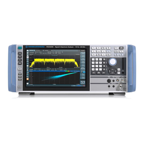
® ® Instrument Tour R&S FSVA3000/R&S FSV3000 Front Panel View Instrument Tour Front Panel View This chapter describes the front panel, including all function keys and connectors. Figure 5-1: Front panel view of R&S FSV/A 1 = POWER key 2 = USB connectors... - Page 36 ® ® Instrument Tour R&S FSVA3000/R&S FSV3000 Front Panel View 5.1.1 Power Key The power key is on the lower left corner of the front panel. It starts up and shuts down the instrument. See also "Connecting to power" on page 9.
- Page 37 ® ® Instrument Tour R&S FSVA3000/R&S FSV3000 Front Panel View System key Assigned functions [File] Provides data management functions such as saving and recall- ing instrument settings or importing and exporting data. Switches between the on-screen keyboard display: ● At the top of the screen ●...
- Page 38 ® ® Instrument Tour R&S FSVA3000/R&S FSV3000 Front Panel View Figure 5-2: Touchscreen elements 1 = Toolbar with standard application functions, e.g. print, save/open file etc. 2 = Tabs for individual measurement channels 3 = Channel bar for firmware and measurement settings...
- Page 39 ® ® Instrument Tour R&S FSVA3000/R&S FSV3000 Front Panel View ● Changing a setting ● Changing the display ● Moving a marker ● Zooming into a diagram ● Selecting a new evaluation method ● Scrolling through a result list or table ●...
- Page 40 ® ® Instrument Tour R&S FSVA3000/R&S FSV3000 Front Panel View Function key Assigned functions [Trace] Configures the measured data acquisition and the analysis of the measurement data. [Trigger] Sets the trigger mode, the trigger threshold, the trigger delay, and the gate configuration for gated sweep.
- Page 41 ® ® Instrument Tour R&S FSVA3000/R&S FSV3000 Front Panel View Function key Assigned functions [Meas Config] Used to define measurement configuration. [Lines] Configures display lines and limit lines. [Input/Output] Displays softkeys for In/Out functions. Measurement start functions [Run Single] Starts a single new measurement (Single Sweep Mode).
- Page 42 ® ® Instrument Tour R&S FSVA3000/R&S FSV3000 Front Panel View ● In lists: toggles between entries ● For markers, limit lines, and other graphical elements on the screen: moves their position ● For active scroll bars: moves the scroll bar vertically ●...
- Page 43 ® ® Instrument Tour R&S FSVA3000/R&S FSV3000 Front Panel View ● The [Redo] key repeats the previously reverted action, i.e. the most recent action is repeated. The [Undo] function is not available after a [Preset] or "Recall" operation. When these functions are used, the history of previous actions is deleted.
- Page 44 ® ® Instrument Tour R&S FSVA3000/R&S FSV3000 Front Panel View available. This connector is suitable as a power supply for high-impedance probes. For details on configuring and using power sensors, see the R&S FSV/A User Manual. 5.1.11 Ext Mixer Connector (Optional) Connect external mixers to the Ext Mixer IF In and LO Out / IF In female connec- tors to increase the available frequency range.
-
Page 45: Rear Panel View
® ® Instrument Tour R&S FSVA3000/R&S FSV3000 Rear Panel View 5.1.14 Keypad The keypad is used to enter alphanumeric parameters, including the correspond- ing units (see also Chapter 7.3.2, "Entering Alphanumeric Parameters", on page 96). It contains the following keys:... - Page 46 ® ® Instrument Tour R&S FSVA3000/R&S FSV3000 Rear Panel View Figure 5-3: Rear panel view 1 = Display Port for external display (requires R&S FSV3-B114) 2 = DVI connector for external display 3 = LAN 1 connector 4 = USB connectors 5 = AC Power Supply Connection and Main Power Switch 6 = LAN 2 (10GBase-T) connector (requires option R&S FSV3-B6)
- Page 47 ® ® Instrument Tour R&S FSVA3000/R&S FSV3000 Rear Panel View 5.2.1 AC Power Supply Connection and Main Power Switch An AC power supply connector and main power switch are located in a unit on the rear panel of the instrument.
- Page 48 ® ® Instrument Tour R&S FSVA3000/R&S FSV3000 Rear Panel View 5.2.4 The rear panel provides four additional female USB (USB-A) connectors to con- nect devices like a keyboard, a mouse or a memory stick (see also Chapter 5.1.2, "USB", on page 36).
- Page 49 ® ® Instrument Tour R&S FSVA3000/R&S FSV3000 Rear Panel View The REF Output connectors can be used to provide an external reference signal (or the optional OCXO reference signal) from the R&S FSV/A to other devices that are connected to this instrument.
- Page 50 ® ® Instrument Tour R&S FSVA3000/R&S FSV3000 Rear Panel View 5.2.12 Aux. Control A 9-pole SUB-D female connector used as input for low-voltage TTL control signals (max. 5 V) from a controlling external device, such as an external generator. This connector is provided by the "Additional Interfaces" option R&S FSV3-B5.
- Page 51 ® ® Instrument Tour R&S FSVA3000/R&S FSV3000 Rear Panel View Table 5-4: Labels regarding R&S FSV/A and environment safety Labeling in line with EN 50419 for disposal of electrical and electronic equipment after the product has come to the end of its service life. For more information, see the prod- uct user manual, chapter "Disposal".
-
Page 52: Trying Out The Instrument
® ® Trying Out the Instrument R&S FSVA3000/R&S FSV3000 Measuring a Basic Signal Trying Out the Instrument This chapter introduces the most important functions and settings of the R&S FSV/A step by step. The complete description of the functionality and its usage is given in the R&S FSV/A User Manual. - Page 53 ® ® Trying Out the Instrument R&S FSVA3000/R&S FSV3000 Measuring a Basic Signal 5. Tap the "Calibration Frequency RF" option. Leave the frequency at the default 64 MHz, with a narrowband spectrum. The calibration signal is now sent to the RF input of the R&S FSV/A. By...
- Page 54 ® ® Trying Out the Instrument R&S FSVA3000/R&S FSV3000 Measuring a Basic Signal To optimize the display To optimize the display for the calibration signal, we will adjust the main measure- ment settings. 1. Set the center frequency to the calibration frequency: a) Tap the "Overview"...
-
Page 55: Displaying A Spectrogram
® ® Trying Out the Instrument R&S FSVA3000/R&S FSV3000 Displaying a Spectrogram Displaying a Spectrogram In addition to the standard "level versus frequency" spectrum display, the R&S FSV/A also provides a spectrogram display of the measured data. A spec- trogram shows how the spectral density of a signal varies over time. The x-axis shows the frequency, the y-axis shows the time. - Page 56 ® ® Trying Out the Instrument R&S FSVA3000/R&S FSV3000 Displaying a Spectrogram Figure 6-3: Adding a Spectrogram to the display Drop the icon. 4. Close the SmartGrid mode by tapping the "Close" icon at the top right corner of the toolbar.
-
Page 57: Activating Additional Measurement Channels
® ® Trying Out the Instrument R&S FSVA3000/R&S FSV3000 Activating Additional Measurement Channels Figure 6-4: Spectrogram of the calibration signal Activating Additional Measurement Channels The R&S FSV/A features multiple measurement channels, i.e. you can define several measurement configurations in parallel and then switch between the channels automatically to perform the measurements sequentially. - Page 58 ® ® Trying Out the Instrument R&S FSVA3000/R&S FSV3000 Activating Additional Measurement Channels 2. On the "New Channel" tab of the "Signal + Spectrum Mode" dialog box, tap the "Spectrum" button. Figure 6-5: Adding a new measurement channel 3. Change the frequency range for this spectrum display: In the "Frequency"...
- Page 59 ® ® Trying Out the Instrument R&S FSVA3000/R&S FSV3000 Activating Additional Measurement Channels Figure 6-6: Frequency spectrum of the calibration signal with a larger span 4. Repeat the previous steps to activate a third Spectrum window. Change the frequency range for this spectrum display: In the "Frequency"...
- Page 60 ® ® Trying Out the Instrument R&S FSVA3000/R&S FSV3000 Activating Additional Measurement Channels Figure 6-7: Time domain display of the calibration signal 5. Create a new channel for I/Q analysis: a) Press the [Mode] key. b) Tap the "IQ Analyzer" button to activate a channel for the I/Q Analyzer application.
- Page 61 ® ® Trying Out the Instrument R&S FSVA3000/R&S FSV3000 Activating Additional Measurement Channels d) Drag the "Real/Imag (I/Q)" icon from the evaluation bar to the SmartGrid. Figure 6-8: Inserting a Real/Imag diagram for I/Q analysis e) Close the SmartGrid mode.
-
Page 62: Performing Sequential Measurements
® ® Trying Out the Instrument R&S FSVA3000/R&S FSV3000 Performing Sequential Measurements Figure 6-9: The "MultiView" tab Performing Sequential Measurements Although only one measurement can be performed at any one time, the measure- ments configured in the active channels can be performed sequentially, that means: one after the other, automatically, either once or continuously. -
Page 63: Setting And Moving A Marker
® ® Trying Out the Instrument R&S FSVA3000/R&S FSV3000 Setting and Moving a Marker Figure 6-10: "MultiView" tab with active Sequencer Figure 6-10, the "Spectrum 2" measurement is currently active (indicated by the "channel active" icon in the tab label). - Page 64 ® ® Trying Out the Instrument R&S FSVA3000/R&S FSV3000 Setting and Moving a Marker 1. In the "MultiView" tab, double-tap the "Spectrum" window (frequency sweep with spectrogram display) to return to the "Spectrum" channel. 2. Tap the spectrum display to set the focus on that window.
-
Page 65: Displaying A Marker Peak List
® ® Trying Out the Instrument R&S FSVA3000/R&S FSV3000 Displaying a Marker Peak List Displaying a Marker Peak List The marker peak list determines the frequencies and levels of peaks in the spec- trum automatically. We will display a marker peak list for the Spectrum 2 channel. - Page 66 ® ® Trying Out the Instrument R&S FSVA3000/R&S FSV3000 Displaying a Marker Peak List 4. Drag the "Marker Peak List" icon from the evaluation bar to the lower half of the display to add a new window for the peak list.
-
Page 67: Zooming Into The Display
® ® Trying Out the Instrument R&S FSVA3000/R&S FSV3000 Zooming into the Display Zooming into the Display To analyze the areas around the peak levels in more detail, we will zoom into the top 3 peaks. Tap the "Multiple Zoom" icon in the toolbar. - Page 68 ® ® Trying Out the Instrument R&S FSVA3000/R&S FSV3000 Zooming into the Display 3. In Figure 6-13, the enlarged peak is represented by a very thick trace. This is due to the insufficient number of sweep points. The missing sweep points for the zoomed display are interpolated, which provides poor results.
- Page 69 ® ® Trying Out the Instrument R&S FSVA3000/R&S FSV3000 Zooming into the Display Figure 6-15: Multiple zoom windows 5. Tap the "Multiple Zoom" icon in the toolbar again and define a zoom area around marker M8. 6. To increase the size of the third zoom window, drag the "splitter" between the windows to the left or right or up or down.
-
Page 70: Zooming Into The Display Permanently
® ® Trying Out the Instrument R&S FSVA3000/R&S FSV3000 Zooming into the Display Permanently Figure 6-16: Enlarged zoom window Zooming into the Display Permanently The zoomed results from Chapter 6.7, "Zooming into the Display", on page 67 were only graphical changes to the display. Now we would like to change the measurement settings such that the zoomed result is maintained permanently. - Page 71 ® ® Trying Out the Instrument R&S FSVA3000/R&S FSV3000 Zooming into the Display Permanently 3. Select the (graphical) zoom icon on the toolbar. Any subsequent touch gestures define the zoom area for the zoom display. 4. Place two fingers on the diagram, to the left and right of the marker, and stretch them apart.
- Page 72 ® ® Trying Out the Instrument R&S FSVA3000/R&S FSV3000 Zooming into the Display Permanently The area around the marker is enlarged in the result display. 5. When the area has the size you require, remove your fingers from the display.
- Page 73 ® ® Trying Out the Instrument R&S FSVA3000/R&S FSV3000 Zooming into the Display Permanently 6. Tap the "Measurement Zoom" icon on the toolbar for a second or so. A context menu with further options is displayed. 7. Select "Adapt Measurement to Zoom (selected diagram)".
-
Page 74: Saving Settings
® ® Trying Out the Instrument R&S FSVA3000/R&S FSV3000 Saving Settings Saving Settings To restore the results of our measurements later, we will store the instrument set- tings to a file. To save the instrument settings to a file Tap the "Save" icon in the toolbar. - Page 75 ® ® Trying Out the Instrument R&S FSVA3000/R&S FSV3000 Saving Settings Figure 6-17: Saving the instrument settings to a file 4. Tap the "Save" button. The file MyMultiViewSetup.dfl is stored in the default directory C:/R_S/ instr/user. To load stored instrument settings You can restore the settings to the instrument at any time using the settings file.
-
Page 76: Printing And Saving Results
® ® Trying Out the Instrument R&S FSVA3000/R&S FSV3000 Printing and Saving Results 3. In the "Load" dialog box, select the MyMultiViewSetup.dfl file in the default directory C:/R_S/instr/user. 4. Tap the "Load" button. All instrument settings are restored and the display should resemble... - Page 77 ® ® Trying Out the Instrument R&S FSVA3000/R&S FSV3000 Printing and Saving Results Figure 6-18: Screenshot of the current display Getting Started 1330.8073.02 ─ 04...
-
Page 78: Operating The Instrument
® ® Operating the Instrument R&S FSVA3000/R&S FSV3000 Understanding the Display Information Operating the Instrument This chapter provides an overview on how to work with the R&S FSV/A. Remote control In addition to working with the R&S FSV/A interactively, located directly at the instrument, it is also possible to operate and control it from a remote PC. - Page 79 ® ® Operating the Instrument R&S FSVA3000/R&S FSV3000 Understanding the Display Information = Channel bar for firmware and measurement settings 2+3 = Window title bar with diagram-specific (trace) information = Diagram area with marker information = Diagram footer with diagram-specific information, depending on measurement application...
- Page 80 ® ® Operating the Instrument R&S FSVA3000/R&S FSV3000 Understanding the Display Information ● Frequency and Span Information in Diagram Footer........86 ● Instrument and Status Information..............86 ● Error Information..................... 87 7.1.1 Channel Bar Using the R&S FSV/A you can handle several different measurement tasks (channels) at the same time (although they can only be performed asynchro- nously).
- Page 81 ® ® Operating the Instrument R&S FSVA3000/R&S FSV3000 Understanding the Display Information Icons in the channel bar yellow star icon on the tab label (sometimes referred to as a "dirty flag") indicates that invalid or inconsistent data is displayed, that is: the trace no longer matches the displayed instrument settings.
- Page 82 ® ® Operating the Instrument R&S FSVA3000/R&S FSV3000 Understanding the Display Information Resolution bandwidth that has been set. If the bandwidth does not correspond to the value for automatic coupling, a green bullet appears in front of the field. Video bandwidth that has been set.
- Page 83 ® ® Operating the Instrument R&S FSVA3000/R&S FSV3000 Understanding the Display Information Table 7-2: Common settings displayed in the channel bar "SGL" The sweep is set to single sweep mode. "Sweep The current signal count for measurement tasks that involve a specific number Count"...
- Page 84 ® ® Operating the Instrument R&S FSVA3000/R&S FSV3000 Understanding the Display Information Changing the Channel Name The measurement channels are labeled with their default name. If that name already exists, a sequential number is added. You can change the name of the measurement channel by double-tapping the name in the channel bar and enter- ing a new name.
- Page 85 ® ® Operating the Instrument R&S FSVA3000/R&S FSV3000 Understanding the Display Information SAMPLE detector AVERAGE detector RMS detector QUASIPEAK detector (4) Trace Mode Sweep mode: Clrw CLEAR/WRITE MAX HOLD MIN HOLD AVERAGE (Lin/Log/Pwr) View VIEW (5) Smoothing factor Smth Smoothing factor, if enabled.
- Page 86 ® ® Operating the Instrument R&S FSVA3000/R&S FSV3000 Understanding the Display Information Trace to which the marker is assigned X-value X-value of the marker Y-value Y-value of the marker Func Activated marker or measurement function Func .Result Result of the active marker or measurement function...
- Page 87 ® ® Operating the Instrument R&S FSVA3000/R&S FSV3000 Understanding the Display Information In the MultiView tab, the status bar always displays the information for the cur- rently selected measurement. The following information is displayed: Instrument status The instrument is configured for operation with an external reference.
-
Page 88: Accessing The Functionality
® ® Operating the Instrument R&S FSVA3000/R&S FSV3000 Accessing the Functionality Table 7-3: Status bar information - color coding Color Type Description Error An error occurred at the start or during a measurement, e.g. due to missing data or wrong settings, so that the measurement cannot be started or completed correctly. - Page 89 ® ® Operating the Instrument R&S FSVA3000/R&S FSV3000 Accessing the Functionality ● Icons on the tool bar in the touchscreen ● Displayed setting on the touchscreen 7.2.1 Toolbar Standard functions can be performed via the icons in the toolbar at theleft side of the screen.
- Page 90 ® ® Operating the Instrument R&S FSVA3000/R&S FSV3000 Accessing the Functionality Icon Description Measurement zoom: applies to the next display you select; Displays a dotted rectangle in the diagram that can be expanded to define the zoom area; the selected diagram is replaced by a new diagram with adapted measurement settings which displays the selected extract of the trace.
- Page 91 Event based actions manager: opens a dialog to configure actions based on specific events For details see General Instrument Setup in the R&S FSV3000/ FSVA3000 base unit user manual. Application starter: opens a dialog to start an external application directly from the R&S FSV/A firmware.
- Page 92 ® ® Operating the Instrument R&S FSVA3000/R&S FSV3000 Accessing the Functionality The "More" softkey indicates that the menu contains more softkeys than can be displayed at once on the screen. When pressed, it displays the next set of soft- keys.
- Page 93 ® ® Operating the Instrument R&S FSVA3000/R&S FSV3000 Accessing the Functionality Figure 7-1: Context menu for a result display with SCPI Recorder functions If SCPI Recorder functions are not available, for example for channel bar settings or in some applications, the context menu contains functions for the selected item.
-
Page 94: Entering Data
® ® Operating the Instrument R&S FSVA3000/R&S FSV3000 Entering Data The on-screen keyboard display can be switched on and off as desired using the "On-Screen Keyboard" function key beneath the screen. When you press this key, the display switches between the following options: ●... - Page 95 ® ® Operating the Instrument R&S FSVA3000/R&S FSV3000 Entering Data Transparent dialog boxes You can change the transparency of the dialog boxes to see the results in the windows behind the dialog box. Thus, you can see the effects that the changes you make to the settings have on the results immediately.
- Page 96 ® ® Operating the Instrument R&S FSVA3000/R&S FSV3000 Entering Data 1. In the input field for a numeric value, select the pencil icon to switch to exten- ded data entry mode. 2. Use the left and right arrow keys to scroll through the individual digits of the indicated value.
- Page 97 For details, see "System Configuration Setttings" in the R&S FSV3000/ FSVA3000 base unit user manual. To enter numbers and (special) characters via the keypad 1. Press the key once to enter the first possible value.
-
Page 98: Touchscreen Gestures
® ® Operating the Instrument R&S FSVA3000/R&S FSV3000 Touchscreen Gestures The dialog box is closed without changing the settings. Table 7-5: Keys for alphanumeric parameters Key name Series of (special) characters and number provided (upper inscription) 7 µ Ω ° € ¥ $ ¢... - Page 99 ® ® Operating the Instrument R&S FSVA3000/R&S FSV3000 Touchscreen Gestures Figure 7-3: Tapping Double-tapping Tap the screen twice, in quick succession. Double-tap a diagram or the window title bar to maximize a window in the display, or to restore the original size.
- Page 100 ® ® Operating the Instrument R&S FSVA3000/R&S FSV3000 Touchscreen Gestures You can pinch or spread your fingers vertically, horizontally, or diagonally. The direction in which you move your fingers determines which dimension of the dis- play is changed. Figure 7-5: Pinching...
- Page 101 ® ® Operating the Instrument R&S FSVA3000/R&S FSV3000 Touchscreen Gestures ● Spreading or pinching a spectrum display changes the center frequency and span (horizontal) or reference level and range (vertical), or a combination of these settings (diagonal). ● Spreading or pinching a time domain display changes the sweep time and trigger offset (horizontal) or reference level position and range (vertical), or a combination of these settings (diagonal).
-
Page 102: Displaying Results
® ® Operating the Instrument R&S FSVA3000/R&S FSV3000 Displaying Results In (graphical) Zoom mode only: dragging the Touch, then drag and release borders of the displayed rectangle to change its size Example: You can scroll through a long table in conventional mouse operation by clicking in the table's scrollbar repeatedly. - Page 103 ® ® Operating the Instrument R&S FSVA3000/R&S FSV3000 Displaying Results To start a new channel 1. Select the [Mode] key. 2. In the "Mode" dialog box, select the required application on the "New Chan- nel" tab. A new tab is displayed for the new channel.
- Page 104 ® ® Operating the Instrument R&S FSVA3000/R&S FSV3000 Displaying Results Select the "Close" icon on the tab of the measurement channel. The tab is closed, any running measurements are aborted, and all results for that channel are deleted. 7.5.2 Laying out the Result Display with the SmartGrid Measurement results can be evaluated in many different ways, for example graphically, as summary tables, statistical evaluations etc.
-
Page 105: Background Information: The Smartgrid Principle
® ® Operating the Instrument R&S FSVA3000/R&S FSV3000 Displaying Results ● Background Information: The SmartGrid Principle........105 ● How to Activate SmartGrid Mode..............106 ● How to Add a New Result Window............... 107 ● How to Close a Result Window..............107 ● How to Arrange the Result Windows............ -
Page 106: How To Activate Smartgrid Mode
® ® Operating the Instrument R&S FSVA3000/R&S FSV3000 Displaying Results 7-8). If an existing window would be replaced, the drop area is highlighted in a darker color shade. Positioning the window The screen can be divided into up to four rows. Each row can be split into up to four columns, where each row can have a different number of columns. -
Page 107: How To Add A New Result Window
® ® Operating the Instrument R&S FSVA3000/R&S FSV3000 Displaying Results the SmartGrid mode is deactivated again, the previous softkey menu display is restored. ► To activate SmartGrid mode, do one of the following: ● Select the "SmartGrid" icon from the toolbar. -
Page 108: How To Arrange The Result Windows
® ® Operating the Instrument R&S FSVA3000/R&S FSV3000 Displaying Results 7.5.2.5 How to Arrange the Result Windows 1. Select an icon from the evaluation bar or the "Move" icon for an existing eval- uation window. 2. Drag the evaluation over the SmartGrid. - Page 109 ® ® Operating the Instrument R&S FSVA3000/R&S FSV3000 Displaying Results The splitters are not available in SmartGrid mode. ► To change the size of two neighboring windows, drag the splitter between the windows in either direction. 7.5.4 Switching Between a Split and Maximized Window Dis-...
-
Page 110: Getting Help
® ® Operating the Instrument R&S FSVA3000/R&S FSV3000 Getting Help Alternatively, double-tap the title bar of a window to maximize it. 7.5.5 Changing the Display The display can be optimized for your individual needs. The following display functions are available and are described in detail in the User Manual. - Page 111 ® ® Operating the Instrument R&S FSVA3000/R&S FSV3000 Getting Help The "Help" dialog box "View" tab is displayed. A topic containing information about the focused screen element is displayed. If no context-specific help topic is available, a more general topic or the "Con- tent"...
- Page 112 ® ® Contacting Customer Support R&S FSVA3000/R&S FSV3000 Contacting Customer Support Technical support – where and when you need it For quick, expert help with any Rohde & Schwarz product, contact our customer support center. A team of highly qualified engineers provides support and works with you to find a solution to your query on any aspect of the operation, program- ming or applications of Rohde &...
- Page 113 ® ® Index R&S FSVA3000/R&S FSV3000 Index Symbols GPIB interface ........48 IF/Video/DEMOD ........ 49 75 Ω (channel bar) ........83 LAN ............. 47 Noise Source Control ......48 OCXO ..........50 AC (channel bar) ........83 Phones ..........44 Alphanumeric parameters ....... 96 Power Sensor ........
- Page 114 ® ® Index R&S FSVA3000/R&S FSV3000 Hiding Screen elements - see User Manual .110 Entering data ........... 94 Error messages Status bar ........... 87 I/Q Analyzer Evaluation Trying out ..........57 Modes, adding ........107 IF/Video/DEMOD Trying out ..........55 Connector ...........
- Page 115 ® ® Index R&S FSVA3000/R&S FSV3000 Measurement channels PHN (marker functions) ......86 Activating .......... 102 Phones Closing ..........103 Connector ........... 44 Measurement zoom .......100 PK (trace information) ......84 Menus POWER Context-sensitive ........ 92 Key ............36 MI (trace information) ......84 Power Sensors MINH (trace information) ......
- Page 116 ® ® Index R&S FSVA3000/R&S FSV3000 Saving Switching Classified data ........32 Focus area .......... 37 Trying out ........74, 76 Keyboard display ........ 37 Screenshots Maximized/split display ....... 37 Trying out ..........76 SWT (channel setting) ......81 Search settings System Trying out ..........
- Page 117 ® ® Index R&S FSVA3000/R&S FSV3000 White papers ........... 14 Window title bar ........84 Windows Adding ..........107 Arranging .......... 108 Closing ..........107 Dialog boxes ........95 Size ........... 108 Windows 10 Access ..........25 Yellow star see Invalid data icon ......81 YIG Bypass (channel bar) .......
Need help?
Do you have a question about the FSVA3000 and is the answer not in the manual?
Questions and answers