Table of Contents
Advertisement
Quick Links
Advertisement
Table of Contents

Related Manuals for R&S FSH series


Summary of Contents for R&S FSH series
- Page 1 R&S®FSH Handheld Spectrum Analyzer Quick Start...
- Page 2 Rohde & Schwarz GmbH & Co. KG Mühldorfstraße 15 81671 München, Germany www.rohde-schwarz.com Customer Support Europe, Africa, Middle East Phone +49 (18 05) 12 42 42 or +49 (89) 41 29-137 74 customersupport@ rohde-schwarz.com North America Phone 1-888-837-87 72 customer.support@ rsa.rohde-schwarz.com Latin America Phone +1-410-910-79 88...
-
Page 3: Table Of Contents
Contents Safety Instructions ......3 Informaciones Elementales de Seguridad ..13 Hints . - Page 4 Getting started ......71 Controlling the RF Attenuator ....71 Using a Preamplifi...
-
Page 5: Safety Instructions
Safety Instructions Make sure to read through and observe the following safety instructions! All plants and locations of the Rohde & Schwarz group of companies make every effort to keep the safety standard of our products up to date and to offer our customers the highest possible degree of safety. - Page 6 safety instructions). Using the product requires technical skills and a basic knowledge of English. It is therefore essential that only skilled and specialized staff or thoroughly trained personnel with the required skills be allowed to use the product. If personal safety gear is required for using Rohde &...
- Page 7 Observing the safety instructions will help prevent personal injury or damage of any kind caused by dangerous situations. Therefore, carefully read through and adhere to the following safety instructions before putting the product into operation. It is also absolutely essential to observe the additional safety instructions on personal safety that appear in relevant parts of the product documentation.
- Page 8 described here are always used only in connection with the related product documentation and the related product. The use of tags in connection with unrelated products or documentation can result in misinterpretation and thus contribute to personal injury or material damage. Basic safety instructions The product may be operated only under the operating conditions and in the positions...
- Page 9 be used for replacing parts relevant to safety (e.g. power switches, power transformers, fuses, batteries). A safety test must always be performed after parts relevant to safety have been replaced (visual inspection, PE conductor test, insulation resistance measurement, leakage current measurement, functional test). As with all industrially manufactured goods, the use of substances that induce an allergic reaction (allergens, e.g.
- Page 10 by electromagnetic radiation. The employer/ operator is required to assess workplaces where there is a special risk of exposure to radiation and, if necessary, take measures to avert the danger. Operating the products requires special training and intense concentration. Make certain that persons who use the products are physically, mentally and emotionally fi...
- Page 11 Never use the product if the power cable is damaged. Check the power cable on a regular basis to ensure that it is in proper operating condition. By taking appropriate safety measures and carefully laying the power cable, ensure that the cable cannot be damaged and that no one can be hurt by e.g.
- Page 12 Unless expressly permitted, never remove the cover or any part of the housing while the product is in operation. Doing so will expose circuits and components and can lead to injuries, fi re or damage to the product. For permanently installed equipment without built-in fuses, circuit breakers or similar protective devices, the supply circuit must be fused in such a way that suitable protection is...
- Page 13 batteries are improperly replaced, this can cause an explosion (warning: lithium cells). Replace the battery or storage battery only with the matching Rohde & Schwarz type (see spare parts list). Batteries and storage batteries must be recycled and kept separate from residual waste.
- Page 14 the driver of the vehicle. The driver is always responsible for the safety of the vehicle. The manufacturer assumes no responsibility for accidents or collisions. Prior to cleaning, disconnect the product from the AC supply. Use a soft, non-linting cloth to clean the product.
-
Page 15: Informaciones Elementales De Seguridad
Informaciones Elementales de Seguridad ¡Es imprescindible leer y observar las siguientes instrucciones e informaciones de seguridad! El principio del grupo de empresas Rohde & Schwarz consiste en tener nuestros productos siempre al día con los estándares de seguridad y de ofrecer a nuestros clientes el máximo grado de seguridad. - Page 16 consecuencias a causa del mal uso del producto. Se parte del uso correcto del producto para los fi nes defi nidos si el producto es utilizado dentro de las instrucciones de la correspondiente documentación de producto y dentro del margen de rendimiento defi...
- Page 17 ¡Advertencia! Superfi cie caliente Conexión a tierra ¡Cuidado! Elementos de construcción con peligro de carga electroestática Tener en cuenta las informaciones de seguridad sirve para tratar de evitar daños y peligros de toda clase. Es necesario de que se lean las siguientes informaciones de seguridad concienzudamente y se tengan en cuenta debidamente antes de la puesta en funcionamiento del producto.
- Page 18 ADVERTENCIA Identifi ca un posible peligro con riesgo medio de provocar muerte o lesiones (de gravedad) si no se toman las medidas oportunas. ATENCIÓN Identifi ca un peligro con riesgo reducido de provocar lesiones de gravedad media o leve si no se toman las medidas oportunas.
- Page 19 (modo de protección IP 51). Si no se convino de otra manera, es para los productos R&S válido lo que sigue: como posición de funcionamiento se defi ne por principio la posición con el suelo de la caja para abajo, modo de protección IP 2X, grado de suciedad 2, categoría de sobrecarga eléctrica 2, utilizar solamente en estancias interiores, utilización hasta 4600 m...
- Page 20 Como en todo producto de fabricación industrial no puede ser excluido en general de que se produzcan al usarlo elementos que puedan generar alergias, los llamados elementos alergénicos (por ejemplo el níquel). Si se producieran en el trato con productos R&S reacciones alérgicas, como por ejemplo urticaria, estornudos frecuentes, irritación de la conjuntiva o difi...
- Page 21 bypass pueden correr peligro a causa de la radiación electromagnética. El empresario/ usuario está comprometido a valorar y señalar áreas de trabajo en las que se corra un riesgo aumentado de exposición a radiaciones para evitar riesgos. La utilización de los productos requiere instrucciones especiales y una alta concentración en el manejo.
- Page 22 bastidores o instalaciones, se deberá instalar el interruptor al nivel de la instalación. No utilice nunca el producto si está dañado el cable eléctrico. Compruebe regularmente el correcto estado de los cables de conexión a red. Asegure a través de las medidas de protección y de instalación adecuadas de que el cable de eléctrico no pueda ser dañado o de que nadie pueda ser dañado por él, por ejemplo...
- Page 23 de medición adecuados, seguros, limitación de tensión, corte protector, aislamiento etc.). En caso de conexión con aparatos de la técnica informática se deberá tener en cuenta que estos cumplan los requisitos del estándar IEC950/EN60950. A menos que esté permitido expresamente, no retire nunca la tapa ni componentes de la carcasa mientras el producto esté...
- Page 24 No ponga el producto sobre aparatos que produzcan calor, como por ejemplo radiadores o calentadores. La temperatura ambiental no debe superar la temperatura máxima especifi cada en la hoja de datos. Baterías y acumuladores no deben de ser expuestos a temperaturas altas o al fuego. Guardar baterías y acumuladores fuera del alcance de los niños.
- Page 25 horquilla, carros etc. El usuario es responsable de que los productos sean sujetados de forma segura a los medios de transporte y de que las prescripciones de seguridad del fabricante de los medios de transporte sean observadas. En caso de que no se tengan en cuenta pueden causarse daños en personas y objetos.
-
Page 26: Hints
Hints Certifi cate of quality Dear Customer, You have decided to buy a Rohde & Schwarz product. You are thus assured of receiving a product that is manufactured using the most modern methods available. This product was developed, manufactured and tested in compliance with our quality management system standards. -
Page 27: Support Center
Support Center For quick, expert help with any Rohde & Schwarz equipment, contact one of our Customer Support Centers. A team of highly qualifi ed engineers provides telephone support and will work with you to fi nd a solution to your query on any aspect of the operation, programming or applications of R0hde &... -
Page 28: Putting Into Operation
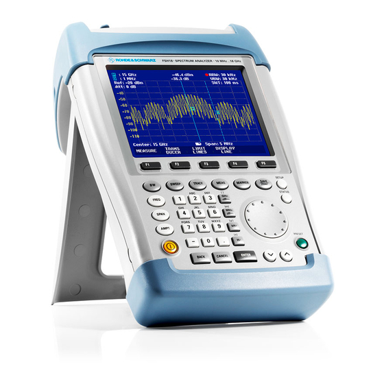
Putting into Operation Front view RF-input N-connector Connector for headphones BNC-connector for: External trigger/external reference input/IF output (IF-Out)/Video Out or BIAS port AUX connection for additional accessories LAN and USB interface Softkey caption Softkeys Function keys (Alpha-)numeric keypad Kensington lock 10 DC connection for supply from the external AC power supply 11 On/Off button... - Page 29 E-02...
-
Page 30: Putting Into Operation
Putting into Operation The following section describes how to put the handheld spectrum analyzer into operation. Section 3 describes the operation of the spectrum analyzer using simple measurements as examples. 2.2.1 Unpacking the Instrument The R&S FSH comes in formfi tting packaging that consists of upper and lower shells. - Page 31 USB cable LAN cable Power supply AC supply plug (country-specifi c) Upper shell R&S FSH Lower shell Lithium ion battery CD-ROM 10 Quick Start manual E-02...
-
Page 32: Setting Up The Instrument
2.2.2 Setting up the Instrument The Handheld Spectrum Analyzer R&S FSH has been designed for operation in labs as well as for on site use for service and maintenance applications. For any application, the R&S FSH can be set up to optimize ease of operation and the viewing angle of the display. -
Page 33: Switching On The Spectrum Analyzer
The carrying handle at the top of the R&S FSH can also be used to hang it from cabinet doors, for example. The shape of the grip ensures that the instrument does not fall off. 2.2.3 Switching on the Spectrum Analyzer The rechargeable lithium ion battery included in the delivery must be inserted into the battery... - Page 34 fully charged when it is dispatched. For battery operation it must therefore fi rst be charged. The charging time when the instrument is switched off is approximately 2.5 hours. If the instrument is switched on, the charging time is extended by approximately one hour to 3.5 hours.
- Page 35 Turn off the R&S FSH while driving or while the engine is on. Operation of the R&S FSH via the cigarette lighter socket while driving or while the engine is on is prohibited. To switch on the R&S FSH, press the yellow button at the bottom left of the front panel.
-
Page 36: Charging The Battery
If the internal battery is completely fl at, the R&S FSH cannot be switched on even though it is connected to the AC supply via the power supply unit. In this case, the internal battery must be charged for a while with the instrument switched off. Only then can the instrument be switched 2.2.4 Charging the Battery... - Page 37 The battery’s charge status is shown at the top right of the screen (see fi gure below). If the battery is fully charged, the battery icon is fi lled white. As the battery discharges, the white coloring disappears in four steps until just the battery outline indicates that the battery is fl...
- Page 38 For rapid charging, be sure to switch off the R&S FSH during charging. If the R&S FSH is switched on, the charging current is reduced by the power drain of the instrument. Battery charging therefore takes longer. The charging times are shown below: Battery type: R&S HA-Z204 (supplied) Charging time (R&S FSH switched off): approx.
- Page 39 Using the R&S HA-Z203 battery charger External charger R&S HA-Z203 Lithium ion battery R&S HA-Z204 or HA-Z206 Power supply unit R&S HA-Z201 or R&S HA-Z202 car adapter For external charging, the lithium ion battery is plugged into the R&S HA-Z203 external charger (available as an accessory: order number 1309.6123.00) and supplied with current via the AC power supply.
-
Page 40: Spectrum Analyzer Connectors
2.2.5 Spectrum Analyzer Connectors The R&S FSH has the following connections on the upper side: RF input Connect the RF input via a cable with an N connector to the DUT. Make sure that it is not overloaded. The maximum permissible continuous power at the RF input is 20 dBm (100 mW). - Page 41 Tracking generator output (general output, models 1309.6000.14, 1309.6000.18, 1309.6000.24 and 1309.6000.28 only) The tracking generator output power for the different R&S FSH models is as follows: Model: R&S FSH4 (1309.6000.14, 1309.6000.18) Frequency: 100 kHz to 3.6 GHz Tracking generator output power: 0 dBm nominal Model: R&S FSH8 (1309.6000.24, 1309.6000.28) Frequency: 300 kHz to 3.6 GHz Tracking generator output power: 0 dBm nominal...
- Page 42 Connection for the power sensor The connection is especially confi gured for power sensors. It is used for both the power supply and data transfer via the power sensor interface. The R&S TS-EMF isotropic antenna (order number 1158.9295.13) can additionally be controlled via this connection.
- Page 43 Input for external trigger or external reference (EXT TRIG/EXT REF) Either an external trigger signal to start a measurement or a 10 MHz reference signal for frequency synchronization is fed in via the EXT TRIG/EXT REF BNC socket. The trigger threshold is similar to that of TTL signals.
- Page 44 Active equipment under test can be supplied with power via the BIAS Port 1 and BIAS Port 2 direct current inputs. Direct current is supplied with the assistance of a suitable power adapter (600 mA max. / 50 V max.). Risk of damage to the instrument Never apply currents above>...
- Page 45 Risk of damage to the instrument Never apply currents above> 600 mA or voltages above 20 V to the BNC sockets if the BNC connectors are not confi gured as BIAS input ports. If the BNC connectors are confi gured as BIAS input ports never apply currents above>...
- Page 46 DC connection for supply from the external AC power supply The R&S FSH is supplied with current by the AC/DC transformer power supply via the DC connection, and the R&S FSH battery is charged. The internal battery can also be charged from a vehicle’s cigarette lighter socket.
-
Page 47: Hardware Settings
2.2.6 Hardware Settings Set the R&S FSH to detect connected accessory automatically. Setting the auto accessory detection Press the SETUP key. Press the INSTRUMENT SETUP softkey. The R&S FSH opens a list of general settings. Select AUTO ACCESSORY DETECTION below the heading HARDWARE with the rotary knob or the cursor keys (∧... -
Page 48: Screen Settings
2.2.7 Screen Settings The R&S FSH’s screen is a TFT color LCD. Indoors, its brightness depends on the intensity of the backlighting. The viewing angle can be optimized by adjusting the color setting. To achieve maximum contrast, the screen can be switched from color display to black-and-white display. - Page 49 Enter the desired brightness value with the rotary knob or the cursor keys in 10 % steps or enter the value directly via the numeric keys. Confi rm with ENTER. The input range lies between 0 % and 100 %. Setting the display color scheme Press the SETUP key.
-
Page 50: Audio Settings
2.2.8 Audio Settings Set the key click volume and the system beeper volume in the INSTRUMENT SETUP settings. Setting the key click volume Press the SETUP key. Press the INSTRUMENT SETUP softkey. The R&S FSH opens a list of general settings. Select KEY CLICK VOLUME below the heading AUDIO with the rotary knob or the cursor keys (∧... - Page 51 Setting the system beeper volume Press the SETUP key. Press the INSTRUMENT SETUP softkey. The R&S FSH opens a list of general settings. Select SYSTEM BEEPER VOLUME below the heading AUDIO with the rotary knob or the cursor keys (∧ or ∨). Confi...
-
Page 52: Regional Settings
2.2.9 Regional Settings The regional settings allow to select a different language, date format and length unit. Set the desired regional settings in the INSTRUMENT SETUP settings. Setting the language Press the SETUP key. Press the INSTRUMENT SETUP softkey. The R&S FSH opens a list of general settings. Select LANGUAGE below the heading REGIONAL with the rotary knob or the cursor keys (∧... -
Page 53: 2.2.10 Setting The Date And Time
Setting the date format Press the SETUP key. Press the INSTRUMENT SETUP softkey. The R&S FSH opens a list of general settings. Select DATE FORMAT below the heading REGIONAL with the rotary knob or the cursor keys (∧ or ∨). Confi... - Page 54 Select the SET DATE menu item below the heading DATE AND TIME with the rotary knob or the cursor keys (∧ or ∨). Confi rm with ENTER. An input fi eld opens. In the input fi eld, the date is shown in the currently selected format: dd/mm/yyyy or mm/dd/yyyy.
-
Page 55: Self Alignment
Change the hours with the rotary knob, the cursor keys or by numeric input. Confi rm with ENTER. After input, the cursor automatically moves to the minutes display. Input is identical to the procedure for setting the hour display. After the minutes have been entered, the R&S FSH verifi... -
Page 56: Setting The Instrument Default Setup
A warning is shown: Pressing YES will perform the self alignment. Pressing NO discards this action. Follow the instructions displayed on the screen. Setting the Instrument Default Setup 2.4.1 Setting Preset The PRESET key sets the R&S FSH to the default setup. -
Page 57: Reset To Factory Settings
2.4.2 Reset to Factory Settings RESET TO FACTORY SETTINGS set the R&S FSH to factory defaults. All settings in the different menus are set to the original factory settings and all saved datasets, user defi ned transducer factors, limit lines, standards, channel tables and cable models will be deleted. -
Page 58: Selecting External Reference / External Trigger / Direct Current Input (Bias Port 2)
Selecting External Reference / External Trigger / Direct Current Input (BIAS Port 2) The Ext Trig / Ext Ref BNC connector on top of the R&S FSH can be used either as an input for an external trigger or an external reference. The BNC socket can additionally be used as a direct current input for PORT 2 (BIAS PORT 2) (see also the chapter on spectrum analyzer connections) -
Page 59: Selecting The Intermediate Frequency Output (If Out) / Direct Current Input (Bias Port 1)
Risk of damage to the instrument Never apply currents above> 600 mA or voltages above 20 V to the BNC sockets if the BNC connectors are not confi gured as BIAS input ports. If the BNC connectors are confi gured as BIAS input ports never apply currents above>... - Page 60 Press the SETUP key. Press the INSTRUMENT SETUP softkey. The R&S FSH opens a list of general settings. Select the BNC2 MODE menu item below the heading HARDWARE with the rotary knob or the cursor keys (∧ or ∨). Confi rm with ENTER. A selection list opens.
-
Page 61: Enabling Options
Enabling Options The R&S FSH can be fi tted with options (e.g. distance-to-fault measurements on cables) which are enabled by entering a key code. The key code is based on the unique serial number of the instrument. To add an option, enable it with a key code. -
Page 62: Checking The Installed Options
Checking the Installed Options The R&S FSH displays the installed options in the Setup menu so you can check them: Press the SETUP key. Press the INSTALLED OPTIONS softkey. The R&S FSH displays all available options with the appropriate status below the header OPTION INSTALLATION STATUS. -
Page 63: Setting Up A Lan Or Usb Connection To A Pc
Setting up a LAN or USB Connection to a PC The powerful R&S FSH4View software is available to document measuring results, create limit lines, channel tables, etc. The software is supplied with the R&S FSH. Connection to a PC is possible via either LAN or USB. - Page 64 DHCP is switched on by default on the R&S FSH. DHCP on the R&S FSH must be switched off for a direct connection. Press the SETUP key. Press the INSTRUMENT SETUP softkey. The R&S FSH opens a list with the general settings. Select the DHCP MODE menu item below the heading LAN PORT with the rotary knob or the cursor keys (∧...
- Page 65 Select the IP ADDRESS menu item from the list under the heading LAN PORT with the rotary knob or the cursor keys (∧ or ∨) and confi rm with ENTER. An input fi eld opens. Enter the IP address of the PC (e.g.
- Page 66 An input fi eld opens. Enter the subnet mask used on the PC, e.g. 255.255.255. 0 with the numeric keys and confi rm with the ENTER key. Fig.: Setting the subnet mask on the R&S FSH R&S FSH4View software confi guration: Start the R&S FSH4View software on the PC.
-
Page 67: Connection Via An Existing Lan Network
The connection is now confi gured and appears in the INSTRUMENT CONNECT window. Select the new connection named “R&S FSH4” and make the connection to the R&S FSH with CONNECT. 2.9.2 Connection via an existing LAN network The R&S FSH’s IP address can be automatically drawn from the DHCP server, or a fi... - Page 68 In networks with a DHCP server, the Dynamic Host Confi guration Protocol (DHCP) permits automatic allocation of the network confi guration to the R&S FSH connected via LAN cable. For this purpose, DHCP must be active on the R&S FSH. DHCP is switched on by default on the R&S FSH.
-
Page 69: Connection Via Usb
The R&S FSH is now allocated an IP address and the subnet mask by the DHCP server. This can take several seconds. The values then appear under IP ADDRESS and SUBNET MASK under the LAN PORT heading. In this example: IP-address: 172.17.75.1 Subnet mask:... - Page 70 Select INSTALL THE SOFTWARE AUTOMATICALLY (RECOMMENDED). Confi rm with NEXT. The R&S FSH4View software must be installed on the PC. Only then can the hardware wizard fi nd the necessary drivers for the USB connection. After a few seconds, the wizard reports that the software for the new hardware has been installed.
- Page 71 Click FINISH to fi nish the installation. The connection is now set up. Open the R&S FSH4View software on the PC. The INSTRUMENT CONNECT dialog opens. Select the USB tab in the INSTRUMENT CONNECT dialog. Select the R&S FSH4 connection. Click CONNECT.
- Page 72 PD 1309.6269.62-02...
-
Page 73: Getting Started
Getting started This section explains the basic operation of the Handheld Spectrum Analyzer R&S FSH using some simple measurements as examples. A more detailed description of operation and functions, such as selecting menus and setting measurement parameters, is given in section 3 of the manual on the CD-ROM. - Page 74 Confi rm with ENTER or the RF ATT/AMP/IMP softkey. The current attenuation value for the RF attenuator is displayed in the status bar at the upper edge of the screen below the Att: caption. To set the attenuator manually, proceed as follows: Press the AMPT key.
- Page 75 The current attenuation value of the attenuator is displayed in the input fi eld. This value can be changed with the rotary knob or the cursor keys in 5 dB steps within the 0 dB to 40 dB range. The desired value can also be entered directly via the numeric keypad.
- Page 76 The set damping value for the attenuator is displayed in the status bar at the upper edge of the screen behind the Att: caption. To re-activate automatic attenuator setting as described, select either AUTO LOW NOISE or AUTO LOW DISTORTION. PD 1309.6269.62-02...
-
Page 77: Using A Preamplifi Er
Using a Preamplifi er The R&S FSH has an internal preamplifi er for increasing sensitivity. Depending on the frequency, this amplifi er has 15 dB to 20 dB gain and increases sensitivity by 10 to 15 dB. It is fi tted behind the RF attenuator and in front of the input mixer. - Page 78 If the preamplifi er is switched on, its use is coupled to the reference level, thus ensuring the optimum dynamic range of the R&S FSH at all times. The table below shows the positions of the RF attenuator and the preamplifi er as a function of the reference level.
-
Page 79: Measurements On Cw Signals
Measurements on CW Signals A basic task performed by spectrum analyzers is measuring the level and frequency of sinewave signals. The following examples illustrate the most effective way of performing these measurements with the R&S FSH. A signal generator is used as a signal source, e.g. the Signal Generator R&S SML. - Page 80 Press the FREQ key. Enter ‘700’ using the numeric keypad and confi rm the entry with the MHz key. Press the SPAN key. Enter ‘10’ using the numeric keypad and confi rm the entry with the MHz key. The R&S FSH now displays the generator signal with a higher resolution.
- Page 81 The R&S FSH has markers for reading off signal levels and frequencies. Markers are always positioned on the trace. Both the level and frequency at their current positions are displayed on the screen. Press the marker key. The marker is activated and is automatically positioned on the trace maximum.
-
Page 82: Setting The Reference Level
3.3.2 Setting the Reference Level The level shown by spectrum analyzers at the top of the measurement diagram is called the reference level (REF LEVEL). To obtain the best dynamic range from a spectrum analyzer, its full level range should be used. This means that the maximum spectrum level should be at or close to the top of the measurement diagram (= reference level). -
Page 83: Frequency Measurements
Using markers is also an effective way to shift the trace maximum so that it coincides with the top of the measurement diagram. If the marker is positioned on the trace maximum (as in the example), the reference level can be set to the marker level by entering the following keystrokes: Press the MARKER->... - Page 84 stops the sweep at the marker position, counts the frequency and then continues the sweep. The following measurement example is based on the previous example. Press the MARKER FUNCTION softkey in the marker menu. The MARKER FUNCTION selection box opens. Select FREQUENCY COUNT from the selection box using the rotary knob or the cursor keys (∧...
-
Page 85: Harmonic Measurements Of A Sinewave Signal
3.3.4 Harmonic Measurements of a Sinewave Signal Since a spectrum analyzer can resolve different signals in the frequency domain, it is ideal for measuring harmonic levels or harmonic ratios. To speed up these operations, the R&S FSH has marker functions that deliver fast results with only a few keystrokes. - Page 86 Press the STOP FREQ softkey. Enter '250' using the numeric keypad and confi rm the entry with the MHz key. The R&S FSH now displays the spectrum from 50 MHz to 250 MHz and thus the signal at 100 MHz and its second harmonic at 200 MHz.
-
Page 87: Power Measurements Using The Power Sensor
Power Measurements Using the Power Sensor For highly accurate power measurements, the R&S FSH provides the Power Sensor R&S FSH-Z1 or R&S FSH-Z18 as options. They measure power in the span 10 MHz to 8 GHz or 10 MHz to 18 GHz, respectively. - Page 88 Risk of damage to the sensor due to high input power • The continuous power applied to the power sensor’s input must not exceed 400 mW (26 dBm). • Use an attenuator for measurements on high- power transmitters. However, brief (≤10 µs) power peaks up to 1 W (30 dBm) are permissible.
- Page 89 The R&S FSH changes to power measurement mode and opens the screen for the power measurement. If a power sensor has not been connected, no measured value is displayed. If a power sensor has been connected, the R&S FSH sets up a connection via the interface and, after a few seconds, displays the measured power.
- Page 90 The R&S FSH immediately starts power meter zeroing. While this process is being performed, the R&S FSH outputs the message “Zeroing power sensor, please wait... ” . When zeroing is over, the R&S FSH outputs the message „Power Sensor Zero OK“ and switches back to the softkey menu for the power sensor.
- Page 91 For a highly accurate measurement, enter the frequency of the signal under test. Press the FREQ softkey. Using the numeric keys, enter the frequency you want and confi rm the entry with the ENTER key or by pressing the FREQ softkey again. The R&S FSH transfers the new frequency to the power sensor which then corrects the measured power readings.
-
Page 92: Power And Return Loss Measurements With The R&S Fsh-Z14 Or The R&S Fsh-Z44
Power and Return Loss Measurements with the R&S FSH-Z14 or the R&S FSH-Z44 The Directional Power Sensors R&S FSH-Z14 and R&S FSH-Z44 are connected between the source and the load and measure the power fl ux in both directions, i.e. from the source to the load (forward power) and from the load to the source (reverse power). - Page 93 When measuring high powers, pay strict attention to the following instructions to avoid personal injury and to prevent the power sensor from being destroyed: Danger of skin burns and damage to the instrument • Never exceed the permissible continuous power. •...
- Page 94 Before performing the power measurement, zero the power sensor. Press the ZERO softkey. The R&S FSH informs you not to apply any signals while the power sensor is being zeroed. Disconnect the power sensor from any signal sources. Start zeroing with the CONTINUE softkey. The softkey CANCEL can be used to cancel zeroing before it begins, e.g.
- Page 95 When zeroing is over, the R&S FSH outputs the message “Power Sensor Zero OK” and switches back to the softkey menu for the power sensor. Now connect the R&S FSH-Z14 or R&S FSH-Z44 between the source and the load. The R&S FSH displays the measured forward power level in dBm and the VSWR of the load.
-
Page 96: Measurement Of The Transfer Function Of Two-Port
Measurement of the Transfer Function of Two-Port Networks (Only for R&S FSH with tracking generator: order no. 1309.6000.14, 1309.6000.18, 1309.6000.24 or 1309.6000.28.) For measurements of the gain or attenuation of four-port devices, the R&S FSH provides a tracking generator which generates a sinewave signal exactly at the receive frequency of the R&S FSH. -
Page 97: Calibrating The R&S Fsh For Vector Measurement Of The Transmission Function
Press the SPAN key. Using the numeric keys, enter the span. Alternately, the start and stop frequencies can be entered using the START FREQ and STOP FREQ softkeys in the frequency menu. 3.6.1 Calibrating the R&S FSH for Vector Measurement of the Transmission Function (Only for R&S FSH models 1309.6000.24 and 1309.6000.28 with option R&S FSH-K42) -
Page 98: Calibrating The R&S Fsh For Scalar Measurement Of The Transmission Function
Connect the generator output with the 50 Ω termination. Press the CONTINUE softkey. When calibration is over, TRANSM. VECTOR (CAL) is displayed in the upper area of the screen to indicate that the R&S FSH is vector-calibrated for transmission measurement. 3.6.2 Calibrating the R&S FSH for Scalar Measurement of the Transmission... - Page 99 Press the MEAS key. Press the MEAS MODE softkey. Using the rotary knob or cursor keys (∧ or ∨), select SCALAR. Confi rm with ENTER or the MEAS MODE softkey. Press the CALIBRATE softkey in the main menu for the network analyzer. With R&S FSH models 1309.6000.24 and 1309.6000.28, the transmission can be measured in a forward or reverse...
-
Page 100: Measure The Magnitude Of The Transfer Function
After the calibration is fi nished, the R&S FSH displays TRANSM. SCALAR (NORM) at the top. 3.6.3 Measure the magnitude of the transfer function After a two-port calibration it is possible to switch between forward and reverse without having to recalibrate the R&S FSH anew. - Page 101 The calibration for the transmission measurement is not lost if the start, stop frequency, the center frequency and the span are subsequently changed within the calibrated frequency domain. In this case, the R&S FSH interpolates the correction data between the reference points of the calibration. In this case, the R&S FSH displays (Approx) at top left and indicates the possibly increased measurement error.
-
Page 102: Return Loss Measurement
Return Loss Measurement (For R&S FSH models with a tracking generator and a built-in VSWR bridge only, order no. 1309.6000.24 or 1309.6000.28) The R&S FSH-Z28 (0 GHz to 8 GHz) or R&S FSH-Z29 (0 GHz to 3.6 GHz) calibration standard is required for measuring the return loss. - Page 103 For measurements on devices under test which require an external voltage supply (e.g. power amplifi ers), connect the supply voltage from a suitable AC power supply to the appropriate BIAS PORT 1 or BIAS PORT 2 input. The test setup must be calibrated prior to the measurement.
-
Page 104: Calibrate The R&S Fsh For The Vector Return Loss Measurement
Alternatively, the start and stop frequency can be input using the START FREQ and STOP FREQ softkeys in the frequency menu. 3.7.1 Calibrate the R&S FSH for the Vector Return Loss Measurement Press the MEAS key. Press the CALIBRATE softkey. Select REFLECTION PORT 1 using the rotary knob or the cursor keys. - Page 105 Terminate the measurement input of the bridge or the end of the measurement cable into a short circuit. Start the short-circuit calibration by pressing CONTINUE. In the third step of calibration, terminate the measurement port into a 50 Ω termination. Terminate the measurement input of the bridge or the end of the measurement cable into a 50 Ω...
-
Page 106: Calibrate The R&S Fsh For The Scalar Return Loss Measurement
3.7.2 Calibrate the R&S FSH for the Scalar Return Loss Measurement The following example shows a scalar measurement of return loss. If the option R&S FSH-K42 is installed, measurement must fi rst be switched to scalar. Press the MEAS key. Press the MEAS MODE softkey. - Page 107 After the calibration is fi nished, the R&S FSH displays (CAL) at the top. This indicates that the R&S FSH is calibrated for scalar refl ection measurements. Scalar refl ection measurements Connect the device under test to the calibrated measurement port. The R&S FSH displays the return loss of the device under test in dB: The R&S FSH additionally offers to display the...
-
Page 108: Restore Calibration Settings
3.7.3 Restore Calibration Settings The calibration remains valid if the start frequency, stop frequency, center frequency and span are subsequently changed within the calibrated frequency range In this case, the R&S FSH interpolates the correction data between the reference points of the calibration. In this case, the R&S FSH displays (Approx) at top left and indicates the possibly increased measurement error. -
Page 109: Using The Factory Calibration
3.7.4 Using the Factory Calibration To use the factory calibration, proceed as follows: Press the CALIBRATE softkey in the main menu for the network analyzer. Select USER CALIBRATION OFF with the rotary knob or the cursor keys (∧ or ∨) and conclude with the ENTER key or the CALIBRATE softkey. -
Page 110: Measuring Cable Faults
Measuring Cable Faults (For R&S FSH models with a tracking generator and a built-in VSWR bridge only, order no. 1309.6000.24 or 1309.6000.28, and installed option R&S FSH-K41 (distance to fault measurement). The R&S FSH-Z20 spare RF cable and the spare FSH-Z28 (0 GHz to 8 GHz) or R&S FSH-Z29 (0 GHz to 3.6 GHz) calibration standard are also required.) Measurement cable... - Page 111 For measurements on devices under test which require an external voltage supply (e.g. power amplifi ers), connect the supply voltage from a suitable AC power supply to the BIAS PORT 1 input. Connect the RF test cable supplied with option R&S FSH-Z20 to PORT 1.
- Page 112 Selecting a cable model from the list Press the MEAS key. Press the CABLE MODEL softkey. The R&S FSH displays the list of loaded cable models. Select the desired cable model with the rotary knob or the cursor keys (∧ or ∨). Using the SELECT softkey, activate the cable model you have selected.
- Page 113 Calibrating the test setup Press the CALIBRATE softkey. Select the DTF ONLY menu item with the rotary knob or the cursor keys (∧ or ∨) and confi rm the selection with the ENTER key or the CALIBRATE softkey. The R&S FSH opens a text window that prompts you to terminate the measurement cable with a SHORT.
- Page 114 Remove the SHORT from the measurement cable. Screw the cable under test to the measurement cable. The R&S FSH displays the return loss produced in the cable under test versus the distance. Checking the spectrum in the span for detecting external interferers Press the MEAS MODE softkey.
- Page 115 Additional measurement of the impedance matching: Apart from the DTF measurement, the R&S FSH offers the option of also determining the cable impedance matching as a function of the frequency. For this purpose, the R&S FSH must be calibrated with three calibration standards (short- circuit, open circuit and 50 ohm match) instead of with just one.
- Page 116 With the REFLECTION setting, the R&S FSH changes from the DTF measurement to measuring the impedance matching and displays this via the frequency. As an indication that the R&S FSH is working in refl ection display mode, it displays DTF REFLECTION at the top of the screen. Otherwise, the R&S FSH uses exactly the same settings as it did for DTF measurements.
-
Page 117: Saving And Recalling Settings And Test Results
Saving and Recalling Settings and Test Results The R&S FSH can store measuring results and settings in the internal memory or on a removable SD memory card. Results and settings are always stored together, allowing them to be interpreted in context when recalled. The R&S FSH can store at least 100 data records in the internal memory which are differentiated by their names. -
Page 118: Saving Measurement Results
3.9.1 Saving Measurement Results Press the SAVE / RECALL key. Press the SAVE softkey. An input box opens and you will be prompted to enter a name for the data set to be saved. The name for the most recently stored data set is suggested in the ‚Name:‘... - Page 119 An existing data record can be selected from the list using the rotary knob or the cursor keys (∧ or ∨). This data record is transferred to the input fi eld by pressing the Enter key. This can then either be overwritten with the current data or saved under a modifi...
- Page 120 Press a cursor key (∧ or ∨). A vertical cursor is positioned at the end of the name for the data set. Use the '∨’ key to move the cursor to the left. Use the '∧’ key to move the cursor to the right. Insert a new letter or number at the cursor position using the alphanumeric keypad.
-
Page 121: Recalling Measurement Results
3.9.2 Recalling Measurement Results Use the R&S FSH’s recall function to review previously saved measurement results and settings. Press the SAVE / RECALL key. Press the RECALL softkey. A list of all saved data sets opens. If a measuring result is to be called from the SD card, press the INTERNAL/SD-CARD softkey. -
Page 122: 3.10 Gps Information Display
3.10 GPS Information Display (requires HA-Z240 GPS receiver, order no.1309.6700.02) Locate your exact position with the GPS receiver function. The GPS receiver function is set in the INSTRUMENT SETUP menu. The reference frequency is automatically adjusted as soon as the GPS receiver function is enabled and there is a fi... - Page 123 Select ENABLED and confi rm with ENTER. Set the coordinate format of the GPS result: Select COORDINATE FORMAT from the list using the rotary knob or the cursor keys (∧ or ∨) and confi rm with ENTER. Select the desired format and confi rm with ENTER.
- Page 124 When the GPS Receiver Function is enabled and there is no fi x connection, this symbol is shown: and the GPS information bar is red: When the GPS Receiver Function is enabled and there is no receiver connected (or not connected properly, or the receiver is defective), this symbol is shown: and the GPS information bar is red:...
-
Page 125: Index
Index Additional accessory (connection, AUX) 40 Audio settings 48 Auto accessory detection 45 AUX (additional accessory, connection) 40 Battery charge 34 external charger R&S HA-Z203 37 BIAS Port 1 direct current input 57 intermediate frequency output (IF Out) 57 BIAS Port 2 direct current input 56 external reference 56 external trigger 56... - Page 126 external reference 56 external trigger 56 External trigger 41 Frequency (measuring) 81 GPS information display 121 enable 120 reference frequency 120 GPS Information Display 120 Hardware Settings 45 Harmonic levels / ratios (measuring) 83 Headphone (connection) 40 IF Out 57 IF output (IF-Out/Video Out) 42 IF-Out/Video Out 42 increasing sensitivity 75...
- Page 127 Kensington Lock 44 Key click volume 48 LAN connection 61 direct connection 61 LAN network 65 Language setting 50 LAN interface 43 Level (measuring) 77 measurement frequency 81 Measurement cable faults 108 CW Signal 77 harmonic levels / ratios 83 level 77 power and return loss 90 power measurement using the power sensor...
- Page 128 Power and return loss (measuring) 90 power measurement 85 Power sensor (connection) 40 power supply unit 35 Preamplifi er 75 Preset 54 Putting into Operation 28 Reference frequency adjust automatically 120 reference level 80 Regional settings 50 Return loss Measurement 100 Return loss measurement (calibration) 104 RF Attenuator 71 RF input 38...
- Page 129 Support Center 25 System beeper volume 49 Tracking generator output 39 transfer function of two-port networks (measu- ring) 94 USB connection 61, 67 USB interface 43 Printed in the Netherlands E-02...
- Page 130 PD 1309.6269.62-02...