Table of Contents
Advertisement
Quick Links
See also:
Manual
Advertisement
Table of Contents

Related Manuals for R&S FSH18


Summarization of Contents
1 Putting into Operation
Unpacking the Instrument
Instructions for safely removing the R&S FSH and its accessories from the packaging.
Setting up the Instrument
Details on positioning and configuring the R&S FSH for optimal use in various environments.
Switching on the Spectrum Analyzer
Step-by-step guide to powering on the R&S FSH using the power supply unit or internal battery.
Spectrum Analyzer Connectors
Identifies and explains the function of each connector on the R&S FSH.
3 Operation
Screen Layout
Explains the visual elements and layout of the R&S FSH display screen.
Entering Measurement Parameters
Describes how to input values, units, and texts for configuring measurements.
4 Instrument Functions
Instrument Default Setup
How to reset the R&S FSH to its factory default settings or presets for new tasks.
Status Display
Overview of how to view and check current measurement parameter settings on the R&S FSH.
Setting the Frequency
Guides on setting center frequency, start/stop frequencies, and offsets.
Specifications
Frequency
Details frequency range, reference frequency, and frequency counter specifications.
Bandwidths
Information on resolution bandwidths and video bandwidth options.
Accessories
Power Sensors R&S FSH-Z1 and R&S FSH-Z18
Details specifications for R&S FSH-Z1 and R&S FSH-Z18 power sensors.
Safety Instructions
Symbols and safety labels
Explains the meaning of various safety symbols and labels used in the documentation.
Safety Instructions
Tags and their meaning
Defines the meaning of hazard tags like DANGER, WARNING, CAUTION, ATTENTION, and NOTE.
Basic safety instructions
Essential guidelines for safe operation, handling, and maintenance of the product.
Customer Support
Technical support – where and when you need it
Details on how to contact customer support centers for assistance with R&S equipment.
Up-to-date information and upgrades
Guidance on subscribing to newsletters and obtaining the latest information and upgrades.
1 Putting into Operation
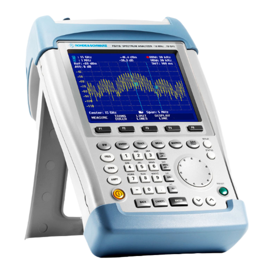
Front view
Identifies and describes the key components and controls visible on the front panel.
1 Putting into Operation
Unpacking the Instrument
Instructions for safely removing the R&S FSH and its accessories from the packaging.
1 Putting into Operation
Setting up the Instrument
Details on positioning and configuring the R&S FSH for optimal use in various environments.
1 Putting into Operation
Switching on the Spectrum Analyzer
Step-by-step guide to powering on the R&S FSH using the power supply unit or internal battery.
1 Putting into Operation
Spectrum Analyzer Connectors
Identifies and explains the function of each connector on the R&S FSH.
1 Putting into Operation
Screen Settings
Covers adjusting screen brightness, contrast, and color settings for optimal viewing.
1 Putting into Operation
Country-Specific Settings
Explains how to set language, date format, and units for regional customization.
1 Putting into Operation
Setting the Date and Time
Instructions for setting the internal clock's date and time on the R&S FSH.
1 Putting into Operation
Charging the Battery
Details the procedure for charging the R&S FSH's internal battery.
1 Putting into Operation
Selecting the Instrument Default Setup
How to apply factory default setups or user-defined configurations.
1 Putting into Operation
External Reference / External Trigger Switchover
Explains how to use the EXT TRIG/EXT REF BNC connector for external signals.
1 Putting into Operation
Controlling the RF Attenuator
How to adjust RF attenuation using LOW NOISE or LOW DISTORTION modes.
Using a Preamplifier
Instructions for enabling or disabling the internal preamplifier for increased sensitivity.
1 Putting into Operation
PIN Entry
Describes how to set up and manage a Personal Identification Number (PIN) for device security.
1 Putting into Operation
Connecting Printers
Instructions for connecting printers via RS-232-C or parallel interfaces using converters.
1 Putting into Operation
Setting the Baud Rate for Remote Control
How to set the baud rate for serial communication for remote control.
Enabling Options
Describes how to enable instrument options using key codes.
1 Putting into Operation
Checking the Installed Options
How to view the currently installed options and their status on the R&S FSH.
2 Getting Started
Measurements on CW Signals
Explains measuring level and frequency of continuous wave signals.
Measurements on CW Signals
Setting the Reference Level
How to set the reference level for optimal dynamic range and display.
Measurements on CW Signals
Frequency Measurements
How to accurately measure signal frequency using markers and frequency counter.
Measurements on CW Signals
Harmonic Measurements of a Sinewave Signal
Steps to measure harmonic levels and ratios of sinewave signals.
Measurements on CW Signals
Power Measurements Using the Power Sensor
How to perform accurate power measurements using external power sensors.
Measurements on CW Signals
Power and Return Loss Measurements with the R&S FSH-Z14 or the R&S FSH-Z44
Using directional power sensors for forward and reflected power measurements.
Measurements on CW Signals
Two-Port Transmission Measurements
Measuring gain or attenuation of two-port devices using the tracking generator.
Measurements on CW Signals
Measurement of Return Loss
How to perform return loss measurements using VSWR bridges.
Measurements on CW Signals
Performing Distance-To-Fault Measurements
Locating cable faults and determining their distance using DTF measurement.
4 Instrument Functions
Using the R&S FSH in receiver mode
How to use the R&S FSH as a receiver for measuring levels at specific frequencies.
4 Instrument Functions
Measuring the Carrier-to-Noise Ratio
How to measure the ratio of carrier power to noise power.
4 Instrument Functions
Saving and Recalling Settings and Test Results
Procedures for saving and loading instrument settings and measurement results.
3 Operation
Screen Layout
Explains the visual elements and layout of the R&S FSH display screen.
3 Operation
Entering Measurement Parameters
Describes how to input values, units, and texts for configuring measurements.
3 Operation
Menu Overview
Provides a visual overview of the R&S FSH menu structure and functions.
3 Operation
Measurement functions
Details various measurement functions available on the R&S FSH.
Measurement functions
Markers
How to use markers for trace analysis, including peak, delta, and multimarker functions.
3 Operation
Instrument setup
Explains how to configure instrument settings like language, display, and hardware.
Status display
How to view and print the current status and settings of the R&S FSH.
4 Instrument Functions
Instrument Default Setup
How to reset the R&S FSH to its factory default settings or presets for new tasks.
Status Display
Overview of how to view and check current measurement parameter settings on the R&S FSH.
Setting the Frequency
Guides on setting center frequency, start/stop frequencies, and offsets.
4 Instrument Functions
Setting the Span
How to adjust the frequency span for optimal measurement views.
4 Instrument Functions
Setting the Amplitude Parameters
Covers setting reference level, display range, units, and RF input impedance.
4 Instrument Functions
Setting the Bandwidths
Explains resolution and video bandwidth settings for signal analysis.
4 Instrument Functions
Setting the Sweep
How to configure sweep time and modes for spectrum analysis.
Setting the Sweep
Sweep mode
Choosing between continuous and single sweep modes.
Trigger
Setting up trigger conditions (free run, video, external) for event-based measurements.
4 Instrument Functions
Trace Settings
Options for managing and displaying measurement traces (clear/write, average, hold, view).
Trace Settings
Detector
Explains the different detector types (peak, average, RMS, quasi-peak) for signal analysis.
Trace Settings
Trace memory
How to store and recall traces for comparison.
4 Instrument Functions
Using the Markers
How to use markers to identify and measure specific points on a trace.
Using the Markers
Automatic marker positioning
Functions for automatically positioning markers on peaks or specific frequencies.
Using the Markers
Using more than one marker at a time (multimarker mode)
How to use multiple markers simultaneously for detailed trace analysis.
Using the Markers
Marker functions
Explains specific marker functions like noise power density and frequency measurement.
4 Instrument Functions
Using the Display Line
How to use a horizontal line on the display for signal level reference.
4 Instrument Functions
Setting and Using the Measurement Functions
Guides on utilizing various measurement functions for advanced analysis.
Measuring the channel power of continuously modulated signals
How to measure the power within a specific transmission channel.
Measuring the channel power of continuously modulated signals
Selecting the standard
Choosing measurement standards for channel power analysis.
Measuring the channel power of continuously modulated signals
Renaming the USER standard
Assigning custom names to user-defined measurement standards.
Measuring the channel power of continuously modulated signals
Setting the reference level
Ensuring the R&S FSH is not overdriven when setting the reference level.
Setting the channel bandwidth
Defining the channel bandwidth for accurate channel power measurement.
Measuring the channel power of continuously modulated signals
Changing the span
Adjusting the frequency span to include signals outside the measurement channel.
Measuring the channel power of continuously modulated signals
Measurement of maximum channel power
Determining the peak resultant field strength using Max Hold.
4 Instrument Functions
Power measurements on TDMA signals
Performing power measurements on time division multiple access signals.
Power measurements on TDMA signals
Measuring the occupied bandwidth
How to measure the bandwidth containing a specified percentage of signal power.
4 Instrument Functions
Measuring the Carrier-to-Noise Ratio
How to measure the ratio of carrier power to noise power.
4 Instrument Functions
Using the R&S FSH in receiver mode
How to use the R&S FSH as a receiver for measuring levels at specific frequencies.
Using the R&S FSH in receiver mode
Setting the frequency
How to set the receiving frequency and step size in receiver mode.
Using the R&S FSH in receiver mode
Setting the bandwidth
Configuring bandwidth settings, including CISPR bandwidths, for receiver mode.
Using the R&S FSH in receiver mode
Setting the detector
Explains the different detector types (peak, average, RMS, quasi-peak) for receiver measurements.
Setting the measurement time
Adjusting the duration for signal observation in receiver mode.
Using the R&S FSH in receiver mode
Measurement on multiple frequencies or channels (scan)
Performing scans across predefined channels or frequencies.
4 Instrument Functions
Measurements using the power sensor
How to connect and use external power sensors for accurate power measurements.
Measurements using the power sensor
Zeroing the power sensor
Procedure for compensating power sensor offsets for accurate readings.
Measurements using the power sensor
Setting the averaging time
Configuring averaging time (fast, normal, long) for display stability.
Measurements using the power sensor
Taking additional loss or gain into account
Compensating for cable attenuation or gain using offset values.
4 Instrument Functions
Measuring forward and reflected power
Measuring power flow in both directions using directional power sensors.
Measuring forward and reflected power
Zeroing the power sensor
Compensating power sensor offsets for accurate readings.
Measuring forward and reflected power
Setting the power measurement weighting
Selecting between average and peak envelope power display.
Measuring forward and reflected power
Selecting the unit for the power readout
Choosing units (dBm, W, dB REL) for displaying power measurements.
Measuring forward and reflected power
Taking additional attenuation into account
Compensating for cable attenuation or gain using offset values.
4 Instrument Functions
Two-port measurements with the tracking generator
Performing transmission and reflection measurements using the tracking generator.
Two-port measurements with the tracking generator
Measuring the transmission of two-ports
Connecting DUT and performing transmission measurements with the tracking generator.
Two-port measurements with the tracking generator
Vector transmission measurement
Performing advanced transmission analysis including phase and group delay.
Vector transmission measurement
Measuring the transmission magnitude
Measuring and displaying the magnitude of the transmission signal.
Measuring the transmission phase
Measuring and displaying the phase characteristics of the transmission signal.
Measuring the transmission phase
Scaling the phase unwrap display
Adjusting the display resolution and scaling for phase measurements.
Two-port measurements with the tracking generator
Measuring the electrical length when measuring transmission
Calculating the electrical length of a DUT from phase delay.
Measuring the electrical length when measuring transmission
Measuring the group delay when measuring transmission
Measuring group delay characteristics of a DUT.
Two-port measurements with the tracking generator
Transmission measurement using the connected VSWR Bridge R&S FSH-Z3
Performing transmission measurements using the VSWR Bridge R&S FSH-Z3.
Two-port measurements with the tracking generator
Spectrum measurements with the VSWR Bridge R&S FSH-Z3 or R&S FSH-Z2 connected
Performing spectrum analysis with connected VSWR bridges.
Two-port measurements with the tracking generator
Settings for detection of the R&S FSH-Z2 and R&S FSH-Z3
Configuring the R&S FSH to detect connected VSWR bridges.
Two-port measurements with the tracking generator
Supplying DC voltage to active DUTs
Providing DC voltage to active DUTs via the VSWR Bridge BIAS inputs.
Reflection measurements
Performing reflection measurements using VSWR bridges.
Reflection measurements
Scalar measurement of reflection
Performing scalar measurements to determine reflection characteristics.
Vector measurement of reflection
Switching on vector measurement
Activating the vector measurement mode for reflection analysis.
Vector measurement of reflection
Calibrating the measurement
Steps for calibrating vector measurements for accurate results.
Vector measurement of reflection
Measuring the reflection magnitude
Measuring and displaying the magnitude of the reflection signal.
Measuring the reflection phase
Measuring and displaying the phase characteristics of the reflection signal.
Vector measurement of reflection
Displaying the reflection in the Smith chart
Visualizing reflection data using the Smith chart.
Using the markers in the Smith chart
How to use markers within the Smith chart display for analysis.
Using the markers in the Smith chart
Selecting the marker format
Choosing different formats for displaying marker data in the Smith chart.
Defining the reference impedance
Defining the reference impedance for accurate Smith chart measurements.
Defining the reference impedance
Zooming in on parts of the Smith chart
Using zoom functions to enlarge specific areas of the Smith chart.
Zooming in on parts of the Smith chart
Measuring the group delay when measuring reflection
Measuring group delay characteristics of reflections.
Two-port measurements with the tracking generator
Settings for detection of the R&S FSH-Z2 and R&S FSH-Z3
Configuring the R&S FSH to detect connected VSWR bridges.
4 Instrument Functions
One-Port Measurement of Cable Loss
Measuring cable loss using the R&S FSH-K2 option.
Cable Measurements
Measurements to determine the characteristics of cables
Key tasks for determining cable characteristics, damage, or connection issues.
Test setup
Connection diagram and steps for setting up cable measurements.
Cable Measurements
Calling the function
Steps to activate the Distance To Fault measurement function.
Cable selection
Selecting predefined or user-defined cable models for accurate measurements.
Cable selection
Selecting a cable model from a predefined list
Choosing a cable model from the R&S FSH's stored list.
Definition of cable parameters on the R&S FSH
Defining cable parameters like frequency, velocity factor, and attenuation.
Definition of cable parameters on the R&S FSH
Preselecting the cable length
Setting the cable length for optimal span and accurate fault location.
Cable Measurements
Calibrating the test setup
Steps for calibrating the test setup for accurate DTF measurements.
Cable Measurements
To select the display unit
Choosing display units for reflection measurements (dB, %, VSWR, etc.).
The R&S FSH can also list any cable faults
Listing detected cable faults and their distance from the measurement plane.
Locating cable faults by means of the marker function
The reference plane to which the distance of a reflection is referred can be redefined
Redefining the reference plane using the marker offset function.
Locating cable faults by means of the marker function
Measuring spectrum and reflection
Performing spectrum analysis and reflection measurements on cables.
4 Instrument Functions
Using Limit Lines
Setting and using limit lines for monitoring signal characteristics against thresholds.
Using Limit Lines
Measurements with limit lines
How the R&S FSH checks for limit violations and displays PASS/FAIL status.
4 Instrument Functions
Measuring with Transducer Factors
Compensating measurements using frequency-dependent transducer factors.
Measuring with Transducer Factors
Operating sequence
Steps to operate and control transducer factor settings.
4 Instrument Functions
Field-Strength Measurement with Isotropic Antenna
Measuring resultant field strength using an isotropic antenna.
Field-Strength Measurement with Isotropic Antenna
To use transducer factors for the isotropic antenna
Activating and applying transducer factors for antenna measurements.
Field-Strength Measurement with Isotropic Antenna
Measurement of the resultant field strength in a transmission channel with large bandwidth
Measuring resultant field strength in wideband transmission channels.
Measurement of the resultant field strength in a transmission channel with large bandwidth
Selecting the standard
Choosing measurement standards for field strength analysis.
Selecting the standard
Renaming the USER standards
Assigning custom names to user-defined measurement standards.
Field-Strength Measurement with Isotropic Antenna
Setting the reference level
Ensuring the R&S FSH is not overdriven when setting the reference level.
Setting the channel bandwidth
Defining the channel bandwidth for field strength measurements.
Setting the channel bandwidth
Changing the frequency span
Adjusting the frequency span to include signals outside the measurement channel.
Measuring the maximum resultant field strength
Determining the peak resultant field strength using Max Hold.
Measuring the maximum resultant field strength
Operation
Steps to control the display of resultant field strength.
Unit for displaying the resultant field strength
Selecting units (dBµV, W/m²) for displaying field strength results.
4 Instrument Functions
Code Domain Power Measurement on 3GPP FDD Signals
Performing CDP measurements according to 3GPP standards.
Code Domain Power Measurement on 3GPP FDD Signals
Display of the channel-specific measurement results
Viewing measurement results for individual channels in CDP analysis.
To simplify operation and to prevent incorrect measurements
Using automatic routines for setting reference level and carrier frequency.
Code Domain Power Measurement on 3GPP FDD Signals
Manual entry of the primary scrambling code
Manually entering the primary scrambling code for 3GPP signal analysis.
Manual entry of the secondary scrambling code
Manually entering the secondary scrambling code for 3GPP signal analysis.
Code Domain Power Measurement on 3GPP FDD Signals
Automatic scrambling code search in the Single mode
Automatically finding the scrambling code of the strongest 3GPP base station signal.
Automatic scrambling code search in the Multiple mode
Automatically finding scrambling codes for multiple 3GPP base stations.
Displaying all scrambling codes found
Viewing a list of all scrambling codes detected and associated CPICH power.
Code Domain Power Measurement on 3GPP FDD Signals
Displaying the EVM symbol for the CPICH and P-CCPCH channel
Viewing the Error Vector Magnitude (EVM) for CPICH and P-CCPCH channels.
Displaying Ec/Io for the CPICH and P-CCPCH channel
Viewing the Ec/Io values for CPICH and P-CCPCH channels.
4 Instrument Functions
Saving and Loading Instrument Settings and Measurement Results
Procedures for saving and loading instrument settings and measurement results.
Saving and Loading Instrument Settings and Measurement Results
Saving results
Steps for saving measurement data sets with specific names.
Saving results
Entering a data set name
How to enter a name for a data set using the alphanumeric keypad.
Loading measurement results
Recalling previously saved measurement results and instrument settings.
Loading measurement results
Deleting saved data sets
How to select and individually delete saved data sets.
Deleting saved data sets
Deleting all data sets
Procedure to completely erase all data sets from the R&S FSH memory.
Saving and Loading Instrument Settings and Measurement Results
Printing out Measurement Results
How to print screenshots and measurement results to a printer.
Measurements
How a spectrum analyzer operates
Explains the fundamental principles of time and frequency domain analysis.
How a spectrum analyzer operates
The precision attenuator
Details the function of the precision attenuator in signal level adjustment.
The mixer
Explains the role of the mixer in converting RF signals to a fixed IF.
A local oscillator
Describes the function of the local oscillator in frequency conversion.
How a spectrum analyzer operates
The video filter comes after the envelope detector
Explains the function of the video filter in smoothing traces and reducing noise.
The detector comes after the video filter
Explains how detectors process video signals to represent spectrum data.
How a spectrum analyzer operates
On the basis of the operating principles of detectors
Recommendations for using different detector types based on signal characteristics.
Need help?
Do you have a question about the FSH18 and is the answer not in the manual?
Questions and answers