Table of Contents
Advertisement
Quick Links
Profile
PRx Performance Retractable Wall Mounted Exercise Rack System, also known
as the Profile Rack and Profile PRO:
U.S. Patent No. 9,333,387
U.S. Patent No. 9,409,048
U.S. Patent No. 9,498,670
U.S. Patent No. 9,649,525
For further assistance and installation video:
prxperformance.com/pages/support
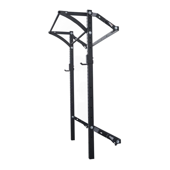
ONE Squat Rack
®
with Kipping™ Bar
U.S. Patent No. 9,844,691
U.S. Patent No. 9,993,678
U.S. Patent No. 10,124,201
U.S. Patent No. 10,632,334
Advertisement
Table of Contents

Related Manuals for PRx Performance Profile ONE Squat Rack with Kipping Bar


Summary of Contents for PRx Performance Profile ONE Squat Rack with Kipping Bar
- Page 1 Profile ONE Squat Rack ® with Kipping™ Bar PRx Performance Retractable Wall Mounted Exercise Rack System, also known as the Profile Rack and Profile PRO: U.S. Patent No. 9,844,691 U.S. Patent No. 9,333,387 U.S. Patent No. 9,993,678 U.S. Patent No. 9,409,048 U.S.
- Page 2 Profile ONE Squat Rack with Kipping Bar ® All Parts & Tools Needed WALL MOUNT BRACKET IS ONE PIECE, BREAK LINES FOR INSTALATION CLARITY WALL MOUNT BRACKET IS ONE PIECE, BREAK LINES FOR INSTALATION CLARITY Rack Specifications (WxHxD) Folded Up: 52” x 108” x 22.5”...
- Page 3 Getting Started 1. Assemble all the tools listed on page 2 and clear your workspace. 2. Measure your stud spacing, ceiling height, and wall width to ensure you have the space to accommodate the rack. Details for those measurements can be found on the next page. 3. Recruit a work partner to assist with lifting and holding the rack. 20.25" 38.25" 21.75" 108.00" 88.00" 19.00" support@prxperformance.com...
- Page 4 Double Check Your Space Standard installation is designed for ceilings 108” or taller. If your ceiling is shorter than 108” please see page 12 for modifications, or contact PRx Performance. 1. Stud Spacing: All Profile® Squat Racks are designed to be mounted to wood studs with standard 16” or 24” spacing, with or without drywall. • To mount your rack to a wall with non-standard stud spacing, please use a stringer board. For more information please email us at support@prxperformance.com. • PRx recommends professional installation for mounting the wall brackets to a block, concrete, or metal stud wall. 2. Ceiling Height: Standard installation is designed for ceilings 108” or taller. If your ceiling is shorter than 108” please see page 12 for modifications to your installation. If you have any questions about these modifications please email us at support@prxperformance.com.
- Page 5 Marking the wall and mounting the brackets Mark Studs 1. Use a stud finder to locate the rightmost stud where you intend to install the right side of your rack. 2. Begin at the height of your lower bracket (19”). 3. With a stud finder, locate the center of the stud and mark it with a pencil. 4. Find and mark the same stud at the height of the upper wall bracket (88”). 5. Locate and mark the remaining three studs in the same fashion. (If your studs are spaced 24”, you will locate only two more). Wall Bracket Helpful Tips 1. Bracket “ears” will point downward. 2. Bracket measurements are on-center (this means measure from the middle of the hole). 3. The distance between the two wall brackets is the MOST IMPORTANT measurement and should take precedence over the bracket distance from the floor (if there is a discrepancy). For the rack to stow properly, this measurement should be made precisely within 1/4”. 4. Standard studs are spaced 16” apart and correspond with the four outside holes. The center hole is only used if studs are spaced 24”. 5. Pilot holes are REQUIRED. Not drilling pilot holes may result in broken lag screws. 6. Drill pilot holes 2” deep using the 7/32” drill bit. Drill as straight as possible. If lag screws are angled during installation, this may result in broken lag screws and unusable locations on your studs. 7. Do NOT overtighten lag screws. Overtightening may strip the pilot hole or break lag screws. To prevent broken lag bolts, avoid using your ratchet or wrench, but instead use your drill or an impact wrench. 8. If, for any reason, you can’t mount the brackets at the recommended height, please use the appropriate table on page 12, or email us at support@prxperformance.com. Mount Lower Bracket 1. Beginnning with the right stud (or if your floors are uneven, start with the lower-side stud), measure 19” up from the floor and drill a pilot hole 2” into the stud.
- Page 6 Attach Linkage Arms to Wall Brackets 1. Place the small side of the plastic spacer (#2) in the straight, gas shock facing portion of unbent end of the linkage arm (as pictured below). 2. Place the linkage arm with the plastic spacer (#2) facing the inside of the wall bracket “ear”. 3. Attach using a 1 3/4” hex head bolt (#10) and 5/8” washer (#3) on the outside of the wall bracket “ear” and a 5/8” washer and 5/8” lock nut (#4) on the opposite side. 4. Tighten using a 15/16” socket and 15/16” wrench. *NOTE: DO NOT over tighten any of the pivot points. This may result in the rack feeling “stiff” moving up and down. It should move up and down freely. 5. Repeat so all four linkage arms are attached to the wall brackets. *NOTE: DO NOT attach the shocks to the wall brackets at this point of assembly. (701) 566-0452...
- Page 7 Attach Kipping Bar To Uprights 1. Lay uprights on the ground facing upward. Leave space between for kipping bar. 2. Lay the kipping bar on the ground as shown in figure 1 with the center of the kipping bar off the ground. 3. Attach kipping bar arms as shown in figure 1 with supplied 1 1/2” hex head bolts and 5/8” lock nuts. Do not fully tighten bolts. 4. Position the kipping bar so that hole B aligns with the top hole of both uprights as shown in figure 2. Using the 4” hex head bolts and 5/8” lock nuts, attach the upright to hole B as shown in figure 2, (hand tighten nuts onto bolts, they will be removed later to attach upper linkage arms) 5. Rotate the kipping bar roughly 90 degrees, until the kipping bar is in a similar position as shown in figure 3 and holes C of the kipping bar arms align with the 5th hole from the top of the uprights. 6. Using the 3 1/2” hex head bolts and 5/8” lock nuts, attach the kipping bar arms hole C to the uprights as shown in figure 3. Make sure to position the plastic kipping bar spacer between the upright and kipping bar arm on both connections, see figure 4. 7. Now is the time! Tighten the bolts in holes A and C. Leave the bolts in holes B hand tightened for now. 8. Team lift the rack into place (approximately 20” from the wall) and begin attaching linkage arms starting at the top. (See next page) Fig. 2 Fig. 1 Fig. 3 Fig. 4 support@prxperformance.com...
- Page 8 Attach Kipping Bar and Linkage Arms Upper Linkage Arms 1. Attach either linkage arm by removing the 5/8” x 4” hex head bolt (#5) from the top of the kipping bar. Place the plastic spacer (#2) on the inside of the linkage arm and place it against the top hole of the upright. 2. Attach linkage arm, black plastic spacer, upright and kipping bar using the 5/8” x 4” hex head bolt (#5), two 5/8” flat washers (#3), and 5/8” lock nut (#4). NOTE: DO NOT over tighten. 3. Repeat on the opposite side. Lower Linkage Arms 1. Place plastic spacer on the inside of the bottom linkage arms, place it against the 19” hole of the upright. Attach linkage arm, plastic spacer (#2) and upright using a 5/8” x 3 1/2” bolt (#6), (2) 5/8” washer (#3) and 5/8” lock nut (#4). DO NOT ATTACH THE SHOCKS. The lower linkage arm should appear at the same angle as the upper linkage arms. 2. Repeat on the opposite side, being sure not to over tighten. (701) 566-0452...
- Page 9 Attach Gas Shocks to Wall Brackets 1. *ATTENTION: TEAM LIFT the rack by holding each upright and pushing up against the wall. NOTE: The rack will be heavy. Use the included bent pin(s) to lock the rack in the up position. 2. Attach the gas shocks to ‘ears’ of the wall brackets with the 5/16” serrated flange nut (#10 already attached to the shock) and tighten using a 7/16” open-ended wrench and 1/2” socket. 3. Repeat for all shocks. 4. Move the rack from the up position to the down position. It should move with ease. If it feels ‘stiff,’ loosen the pivot points slightly until it moves smoothly. That’s it! Please send a video or photo of your rack in action to sales@prxperformance.com when complete. We would love to see it! support@prxperformance.com...
- Page 10 You’ve got your equipment, now get your workouts. PRx Fit offers free and upgradeable daily workouts to accommodate your schedule and maximize your home gym. Free workout programs! Scan the code or follow the link to download the app. Compete against others! http://onelink.to/xfvf5f (701) 566-0452...
- Page 11 LIMITED LIFETIME WARRANTY This product is warranted by PRx Performance LLC, to the original user-owner only, against defective materials or workmanship for the lifetime of the product. During the warranty period, or “lifetime” of the product, at the discretion of PRx management, if the product is found to be defective, it will be repaired or replaced without charge. Said “lifetime”...
- Page 12 Wall Bracket Heights According to Ceiling Heights Standard installation is designed for ceilings 108” or taller. If your ceiling is shorter than 20.25” 108”, please refer to the table below and use the bracket height measurements that 35.75” correspond to your ceiling height. 19.25” Some modified installations will result in a shallower rack depth and linkage arms will be at an angle when the rack is deployed. Ceiling Bottom Space Rack Height Bracket Bracket Between Depth 108” 19” 88” 69” 21.75” 107” 18” 87” 69” 21.75” 106” 17” 86” 69” 21.75” 99.00” 105” 16” 85” 69”...
Need help?
Do you have a question about the Profile ONE Squat Rack with Kipping Bar and is the answer not in the manual?
Questions and answers