Advertisement
Quick Links
Tool List
•
15/16" Open End Wrench
•
7/16" Open End Wrench
•
1/2" Open End Wrench
•
15/16" Socket
•
1/2" Socket
•
Ratchet
•
4' Level
•
Plumb Bob
•
7/32" Drill Bit
•
Cordless Drill
•
Impact Driver
•
Stud Finder
•
Tape Measure
•
Pencil
Item # Description
1
Left Wall Bracket
2
Right Wall Bracket
3
5/16" x 2-1/2" Lag Screw 8
4
5/16" Flat Washer
5
5/8" Flat Washer
6
5/8" Lock Nut
7
5/8" x 3-1/2" Hex Bolt
8
5/8" x 1-3/4" Hex Bolt
9
Multi-Grip Bar
10
5/8" x 4" Hex Bolt
11
89" Upright
12
Bent Hitch Pin
13
Plastic Spacer
14
Linkage Arm
15
Gas Shocks
16
Flange Nuts
• This installation requires two people.
• Standard installation is designed for ceilings 107" or taller. If your ceilings are
shorter than 107" please refer to the table on page 3 and use the bracket height
measurements that correspond to your ceiling height.
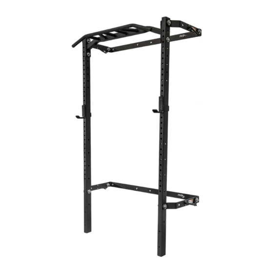
89" Profile® ONE Rack with Multi-Grip Bar
Qty.
2
2
8
20
10
4
4
1
2
2
1
(not shown)
8
4
4
8
060223_Rev. 1
Advertisement

Related Manuals for PRx Performance Profile ONE


Summary of Contents for PRx Performance Profile ONE
- Page 1 89” Profile® ONE Rack with Multi-Grip Bar Tool List • 15/16” Open End Wrench • 7/16” Open End Wrench • 1/2” Open End Wrench • 15/16” Socket • 1/2” Socket • Ratchet • 4’ Level • Plumb Bob • 7/32” Drill Bit •...
-
Page 2: Getting Started
Getting Started 1. Assemble all tools listed on page 1 and clear your workspace. 2. Check the stud spacing of your wall: All Profile® Squat Racks are designed to be mounted to wood studs with standard 12”, 16”, or 24” spacing. •... - Page 3 Modified Install Standard installation is designed for ceilings 107” or taller. If your ceiling is shorter than 107” please refer to the table below and use the bracket hole height measurements that correspond to your ceiling height. Some modified installations will result in a shallower rack depth and linkage arms will be at an angle when deployed.
-
Page 4: Installing The Wall Brackets
Installing the Wall Brackets Begin by determining if your floor slopes down to the left, down to the right, or is flat. See Figure 2. If it slopes down to the left, start with the far-left stud. If it slopes down to the right, start with the far-right stud. - Page 5 6. Align the wall bracket over the drilled holes so the ear of the wall bracket is facing down and out. Using an impact driver and 1/2” socket, fasten the first upper wall bracket to the wall with two 5/16” lag screws (3) and washers (4) (Figure 3).
- Page 6 10. Place the 4-foot level against the bottom edge of the first upper wall bracket, span it to the next marked stud 48” away, and mark the wall once leveled (Figure 3). 11. Place the second upper wall bracket so the bottom aligns to the level mark, and mark the location of the holes on the stud.
- Page 7 Installing the Linkage Arms 1. Place the small side of the plastic spacer (13) into the linkage arm (14) (Figure 6). 2. Place the linkage arm with the plastic spacer facing the inside of the wall bracket “ear”. 3. Attach the linkage arm to the wall bracket using a 1-3/4” hex head bolt (8) and 5/8” washer (5) on the outside of the wall bracket “ear”...
- Page 8 Attach Multi-Grip to Uprights 1. Lay the uprights on the ground facing upwards. Leave space between them for the Multi-Grip Bar. 2. Lay the Multi-Grip Bar on the ground (Figure 7) with the bar facing up between the uprights. 3. Position the Multi-Grip Bar (9) so that the holes align with the top hole of both uprights (Figure 7). Using the 4”...
- Page 9 Attaching The Linkage Arms 1. Team lift the rack into place (approximately 20” from the wall) and begin attaching the linkage arms starting at the top. 2. Undo one 5/8” x 4” hex bolt (10) and bolt the linkage arm to the upright through the Multi-Grip Bar using the 5/8”...
- Page 10 Attaching the Gas Shocks 1. With another person, lift the rack to fold it into the up position. 2. Use the included bent hitch pin (12) to lock the rack in the up position (Figure 10). 3. Insert the stud of the gas shock through the hole in the wall bracket as shown below. 4.
Need help?
Do you have a question about the Profile ONE and is the answer not in the manual?
Questions and answers