Table of Contents
Advertisement
Advertisement
Table of Contents

Subscribe to Our Youtube Channel
Related Manuals for Launch Creader 629


Summary of Contents for Launch Creader 629
- Page 1 V1.00.001 05-27-2020...
- Page 2 Statement: LAUNCH owns the complete intellectual property rights for the software used by this product. For any reverse engineering or cracking actions against the software, LAUNCH will block the use of this product and reserve the right to pursue their legal liabilities.
- Page 3 LAUNCH 629 User's Manual Operating or observing the tool will cause driver distraction and could cause a fatal accident. • Wear safety eye protection that meets ANSI standards. • Keep clothing, hair, hands, tools, test equipment, etc. away from all moving or hot engine parts.
-
Page 4: Table Of Contents
LAUNCH 629 User's Manual Table of Contents 1. Introduction ....................1 2. General Information-About OBDII/EOBD ..........3 2.1 On-Board Diagnostics (OBD) I ..............3 2.2 On-Board Diagnostics (OBD) II ..............3 2.3 Diagnostic Trouble Codes (DTCs) ..............5 2.4 Location of the Data Link Connector (DLC)..........6 2.5 OBD II Terminology ..................7... - Page 5 LAUNCH 629 User's Manual 7.1 DLC Location Information .................38 7.2 Abbreviation ....................38 7.3 Tool Information ..................38 7.4 About OBD....................39 7.5 Upgrade Information .................39 8. Register & Update ..................40 9. FAQ ......................43 www.x431.com +86 755 8455 7891...
-
Page 6: Introduction
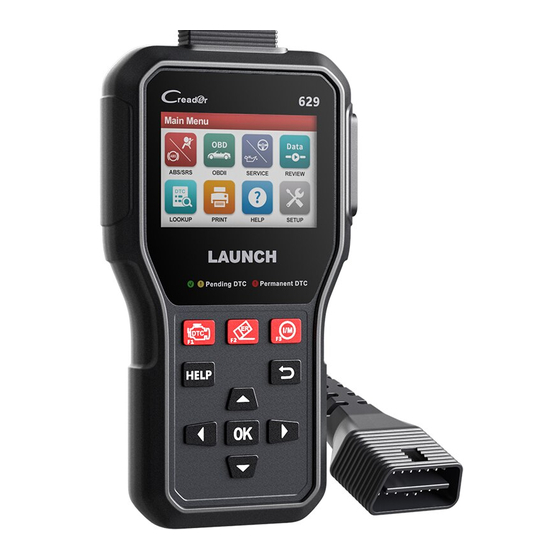
629 User's Manual 1. Introduction This OBD II scanner is specially developed by LAUNCH, which supports all 10 modes of OBD II test for a complete diagnosis. Featuring the 3.5” TFT color display, it enables users to read/clear DTCs, record, save and playback data in live graphic display. - Page 7 LAUNCH 629 User's Manual compliant, the label will designate “OBD II Certified”. 2. Government regulations mandate that all OBD II compliant vehicles must have a “common” 16-pin Data Link Connector (DLC). Note: Some 1994 and 1995 vehicles have 16-pin connectors but are not OBD II compliant.
-
Page 8: General Information-About Obdii/Eobd
LAUNCH 629 User's Manual 2. General Information-About OBDII/EOBD 2.1 On-Board Diagnostics (OBD) I Note: With the exception of some 1994 and 1995 vehicles, most vehicles from 1982 to 1995 are equipped with some type of first generation On-Board Diagnostics. Beginning in 1988, California’s Air Resources Board (CARB), and later the Environmental Protection Agency (EPA) required vehicle manufacturers to include a self-diagnostic program in their on-board computers. - Page 9 LAUNCH 629 User's Manual showed the following: • A large number of vehicles had deteriorating or degraded emissions-related components. These components were causing an increase in emissions. • Because OBD I systems only detect failed components, the degraded components were not setting codes.
-
Page 10: Diagnostic Trouble Codes (Dtcs)
LAUNCH 629 User's Manual • To standardize communication procedures and protocols between the diagnostic equipment (Diagnostic Tools, Code Readers, etc.) and the vehicle’s on-board computer. 2.3 Diagnostic Trouble Codes (DTCs) OBD II Diagnostic Trouble Codes are codes that are stored by the on-board computer diagnostic system in response to a problem found in the vehicle. -
Page 11: Location Of The Data Link Connector (Dlc)
LAUNCH 629 User's Manual P0201 - Injector circuit malfunction, Cylinder 1 2.4 Location of the Data Link Connector (DLC) The DLC (Data Link Connector or Diagnostic Link Connector) is the standardized 16-cavity connector where diagnostic code readers interface with the vehicle’s on-board computer. The DLC is usually located 12 inches from the center of the instrument panel (dash), under or around the driver’s side for... -
Page 12: Obd Ii Terminology
LAUNCH 629 User's Manual most vehicles. If Data Link Connector is not located under dashboard, a label should be there telling location. For some Asian and European vehicles, the DLC is located behind the ashtray and the ashtray must be removed to access the connector. - Page 13 LAUNCH 629 User's Manual specific events or conditions that must occur within the engine before the various monitors will set, or run. Some monitors require the vehicle to follow a prescribed “drive cycle” routine as part of the enabling criteria. Drive cycles vary among vehicles and for each monitor in any particular vehicle.
-
Page 14: Obd Ii Monitors
LAUNCH 629 User's Manual refers to much more gradual adjustments to the fuel calibration schedule than short-term trim adjustments. These long-term adjustments compensate for vehicle differences and gradual changes that occur over time. 2.6 OBD II Monitors An important part of a vehicle’s OBD II system is the Readiness Monitors, which are indicators used to find out if all of the emissions components have been evaluated by the OBD II system. - Page 15 LAUNCH 629 User's Manual to “flash” once per second as soon as the misfire is sensed. When the misfire is no longer present, the MIL reverts to steady “On” condition. The Misfire Monitor is supported by both “spark ignition” vehicles and “compression ignition”...
-
Page 16: Non-Continuous Monitors
LAUNCH 629 User's Manual The “non-continuous” Monitors are: 1. O Sensor Monitor The Oxygen Sensor monitors how much oxygen is in the vehicle’s exhaust. It generates a varying voltage of up to one volt, based on how much oxygen is in the exhaust gas, and sends the signal to the computer. - Page 17 LAUNCH 629 User's Manual In order for the computer to enter closed-loop operation, the oxygen sensor must reach a temperature of at least 600°F. The oxygen sensor heater helps the oxygen sensor reach and maintain its minimum operating temperature (600°F) more quickly, to bring the vehicle into closed-loop operation as soon as possible.
- Page 18 LAUNCH 629 User's Manual Heated Catalyst Monitor performs the same diagnostic tests as the catalyst Monitor, and also tests the catalytic converter’s heater for proper operation. The Heated Catalyst Monitor is supported by “spark ignition” vehicles only. This Monitor is also a “Two-Trip” Monitor.
-
Page 19: Obd Ii Reference Table
LAUNCH 629 User's Manual this Monitor once per trip. The EVAP Monitor is supported by “spark ignition” vehicles only. The EVAP Monitor is a “Two-Trip” Monitor. If a fault is found on the first trip, the computer temporarily saves the fault in its memory as a Pending Code. The computer does not command the MIL on at this time. - Page 20 LAUNCH 629 User's Manual D. Number of trips needed, with no faults present, to erase a Pending DTC. E. Number and type of trips or drive cycles needed, with no faults present, to turn off the MIL. F. Number of warm-up periods needed to erase the DTC from the computer’s memory after the MIL is turned off.
-
Page 21: Dtcs And Mil Status
LAUNCH 629 User's Manual related component or system, the computer’s internal diagnostic program assigns a diagnostic trouble code (DTC) that points to the system (and subsystem) where the fault was found. The diagnostic program saves the code in the computer’s memory. It records a “Freeze Frame” of conditions present when the fault was found, and lights the Malfunction Indicator Lamp (MIL). - Page 22 LAUNCH 629 User's Manual The MIL will stay lit for both Type “A” and Type “B” codes until one of the following conditions occurs: • If the conditions that caused the MIL to light are no longer present for the next three trips in a row, the computer automatically turns the MIL “Off”...
-
Page 23: Product Descriptions
LAUNCH 629 User's Manual 3. Product Descriptions 3.1 General Controls Name Notes DB-15 DIAGNOSTIC Connects the tool to the vehicle’s Data CONNECTOR Link Connector (DLC). www.x431.com +86 755 8455 7891... - Page 24 LAUNCH 629 User's Manual Connects the tool to computer via USB USB PORT cable for upgrade. Insert the memory card into it to read or MEMORY CARD write the data/file stored in the memory SLOT card. BUTTON* Clears the diagnostic trouble codes.
-
Page 25: Specifications
LAUNCH 629 User's Manual The following (green, yellow and red LEDs) are used as visual aids to make it easier to determine engine system conditions. • GREEN LED (No Fault Code): Indicates that all engine systems are running normally (all Monitors on the... - Page 26 LAUNCH 629 User's Manual 5) USB cable -- Connect to a computer for upgrading online 6) Quick Start Guide www.x431.com +86 755 8455 7891...
-
Page 27: Initial Use
LAUNCH 629 User's Manual 4. Initial Use 4.1 Connection 1). Turn the ignition off. Figure 4-1 2). Locate the vehicle’s 16-pin Data Link Connector (DLC). Refer to Chapter 2.4. 3). Plug the diagnostic cable of the tool into the vehicle’s DLC. -
Page 28: Main Menu
LAUNCH 629 User's Manual 4). Turn the ignition on. Engine can be off or running. CAUTION: Don’t connect or disconnect any test equipment with the ignition on or engine running. 5). The system automatically turns on and navigates to the main menu screen. -
Page 29: Settings
LAUNCH 629 User's Manual Allows you retrieve the desired DTC and view its detailed LOOKUP definition. Prints the diagnostic records saved during diagnostic session. PRINT *Note: This function required a USB cable connection to PC. Helps you have a general knowledge of the DLC location, HELP tool information and OBD etc. -
Page 30: Diagnose
LAUNCH 629 User's Manual 5. Diagnose 5.1 OBDII/EOBD Diagnosing This option presents a quick way to check for DTCs, isolate the cause of the illuminated Malfunction Indicator Lamp (MIL), check monitor status prior to emissions certification testing, verify repairs, and perform a number of other services that are emission-related. - Page 31 LAUNCH 629 User's Manual Figure 5-2 It mainly includes the following functions: 1. Read Codes This function allows you to view the Diagnostic Trouble Codes (DTCs) retrieved from the vehicle’s on-board computer. Note: Never replace a part based only on the DTC definition. Each DTC has a set of testing procedures, instructions and flow charts that must be followed to confirm the location of the problem.
- Page 32 LAUNCH 629 User's Manual In Figure 5-3, • A - DTC: Displays the Diagnostic Trouble Code (DTC) number. Each fault is assigned a code number that is specific to that fault. • B - Code Number Sequence: The tool assigns a sequence number to each DTC that is present in the computer’s memory, starting with “1.”...
- Page 33 LAUNCH 629 User's Manual Note: In case the diagnostic codes are manufacturer-specific, users need to select the manufacturer manually and the following prompt message will pop up on the screen. Figure 5-4 Press [OK] to enter to select the manufacturer. Figure 5-5 will be shown on the screen.
- Page 34 LAUNCH 629 User's Manual Figure 5-6 2. Erase Codes Note: When this function is used to erase DTCs from the vehicle’s on-board computer, “Freeze Frame” data is erased and “Permanent” DTCs ARE NOT erased. If you plan to take the vehicle to a Service Center for repair, DO NOT erase the codes from the vehicle’s computer.
- Page 35 LAUNCH 629 User's Manual the various emissions-related systems on the vehicle are operating properly and are ready for Inspection and Maintenance testing. The purpose of the I/M Readiness Monitor Status is to indicate which of the vehicle’s Monitors have run and completed their diagnosis and testing, and which ones have not yet run and completed testing and diagnosis of their designated sections of the vehicle’s emissions system.
-
Page 36: System Diagnosing
LAUNCH 629 User's Manual 7. On-board monitor test This function can be utilized to read the results of on-board diagnostic monitoring tests for specific components/systems. 8. EVAP System Test The EVAP test function lets you initiate a leak test for the vehicle’s EVAP system. -
Page 37: Service
LAUNCH 629 User's Manual Select “ABS/SRS” Read version information Read fault code Select Vehicle Select test function Manufacturer Clear fault code Read data stream Select Vehicle Model Action Test (only (Note: For different vehicles, vehicle make selection may available in Select scan mode differ. -
Page 38: Review
LAUNCH 629 User's Manual Select "SERVICE" Choose the desired service function (e.g. oil lamp reset etc.) Select the desired car brand Select the reset mode (The available mode varies from vehicle to vehicle) Follow the on-screen instructions to proceed 5.4 Review This function is used to review or delete the recorded DTC, Data Streams and Freeze Frame. - Page 39 LAUNCH 629 User's Manual Figure 5-7 Press [ ] / [ ] to move the highlight bar to different position. Press [ ] / [ ] button to alter the value, then press [OK] button, the screen will display the detailed definition of the DTC.
-
Page 40: Print
(For details, refer to Chapter 8 Register & Upgrade). 1. Launch the update tool, a screen similar to Fig. 6-1 will appear: Figure 6-1 2. Connect one end of the USB cable to your tool, and the other end on the computer. - Page 41 LAUNCH 629 User's Manual Note: After the system identified the scanner information, it will display in gray in Product Serial Number input box and the "Print Manager" module will be activated immediately. 4. Click [Print Manager] to enter the print manager screen.
- Page 42 LAUNCH 629 User's Manual Figure 6-4 On-screen buttons: : Allows you to modify the personal information. Configured information is automatically generated and displayed on the top of the report each time the diagnostic report is synchronized on the computer. Figure 6-5 : Exports the current report on the local disk on the computer.
-
Page 43: Help
LAUNCH 629 User's Manual 7. Help This menu enables you to view device information and OBD introduction. On the main menu screen, select [Help] and press [OK] to enter the following screen. Figure 7-1 7.1 DLC Location Information This option helps you to find the location of the vehicle’s DLC. -
Page 44: About Obd
LAUNCH 629 User's Manual Figure 7-2 Note: You are strongly recommended to note down the Serial Number and Register Code in Figure 7-3 since these 2 pieces of information are required while registering your tool. Press [ ] to return to the previous screen. -
Page 45: Register & Update
LAUNCH 629 User's Manual 8. Register & Update Prerequisite conditions: 1. Go to http://www.x431.com/CR629 to download the update tool and install it on the computer. 2. System requirements: Windows XP, 7, 8 or Windows 10. The tool can be updated via memory card. - Page 46 For better experience, it is recommended to register and upgrade the tool first. But if not, the tool can also be used normally. 1). Launch the update tool, a screen similar to Fig. 8-3 will appear: Figure 8-3 Note: After the Product Serial Number is entered, it will display in gray and the "Print Manager"...
- Page 47 LAUNCH 629 User's Manual Figure 8-4 3). Enter the required E-mail address and Register Code, click [Submit] to finish the sign-up. Note: For initial update, user needs to go through a registration process. Once you finished it, the registration screen will not appear again each time you click the [Device Upgrade] button in the future.
-
Page 48: Faq
LAUNCH 629 User's Manual 9. FAQ Here we list some frequently asked questions and answers relating to this tool. Question: System halts when reading data stream. What is the reason? Answer: It may be caused by a slackened connector. Please turn off the tool, firmly connect the connector, and switch it on again. - Page 49 The exclusive remedy for any automotive meter found to be defective is repair or replacement, and LAUNCH shall not be liable for any consequential or incidental damages.
Need help?
Do you have a question about the Creader 629 and is the answer not in the manual?
Questions and answers