Table of Contents
Advertisement
Advertisement
Table of Contents

Related Manuals for Launch CRT5011E


Summary of Contents for Launch CRT5011E
- Page 1 LAUNCH CRT5011E User Manual V1.00.002 08-12-2020...
- Page 2 Statement: LAUNCH owns the complete intellectual property rights for the software used by this product. For any reverse engineering or cracking actions against the software, LAUNCH will block the use of this product and reserve the right to pursue their legal liabilities.
- Page 3 LAUNCH the warranty right. • CAUTION: This tool contains an internal Lithium Polymer battery. The battery can burst or explode, releasing hazardous chemicals. To reduce the risk of fire or burns, do not disassemble, crush, pierce or dispose of the battery in fire or water.
- Page 4 LAUNCH nearby. • Don’t connect or disconnect any test equipment while the ignition is on or the engine is running. FCC Statement This device complies with Part 15 of the FCC Rules. Operation is subject to the following two conditions:...
-
Page 5: Table Of Contents
LAUNCH Table of Contents 1. Introduction ....................1 2. General Information-About OBDII/EOBD ..........3 2.1 On-Board Diagnostics (OBD) I ..............3 2.2 On-Board Diagnostics (OBD) II ..............3 2.3 Diagnostic Trouble Codes (DTCs) ..............5 2.4 Location of the Data Link Connector (DLC)..........6 2.5 OBD II Terminology ..................7 2.6 OBD II Monitors ..................9... - Page 6 LAUNCH 5.2.3 Copy ID by activation...............36 5.2.4 Program multi-sensor ..............38 5.3 TPMS Service ...................39 5.3.1 Relearn procedure ................39 5.3.2 Part number lookup .................40 6. OBD Diagnosing ..................41 6.1 Connection ....................41 6.2 Start OBD Diagnostics................42 7. Help ......................52 7.1 DLC Location Information .................52 7.2 Tool Information ..................52...
-
Page 7: Introduction
LAUNCH 1. Introduction This TPMS activation & diagnostic tool is specially developed by LAUNCH, which enables users to trigger TPMS sensor, program TPMS sensor, perform the relearning procedure and check sensor part number. Additionally, it also supports all 10 modes of OBD II test for a complete diagnosis. - Page 8 LAUNCH 1. Vehicle Emissions Control Information (VECI) Label. It is located under the hood or by the radiator of most vehicles. If the vehicle is OBD II compliant, the label will designate “OBD II Certified”. 2. Government regulations mandate that all OBD II compliant vehicles must have a “common”...
-
Page 9: General Information-About Obdii/Eobd
LAUNCH 2. General Information-About OBDII/EOBD 2.1 On-Board Diagnostics (OBD) I Note: With the exception of some 1994 and 1995 vehicles, most vehicles from 1982 to 1995 are equipped with some type of first generation On-Board Diagnostics. Beginning in 1988, California’s Air Resources Board (CARB), and later the Environmental Protection Agency (EPA) required vehicle manufacturers to include a self-diagnostic program in their on-board computers. - Page 10 LAUNCH showed the following: • A large number of vehicles had deteriorating or degraded emissions-related components. These components were causing an increase in emissions. • Because OBD I systems only detect failed components, the degraded components were not setting codes.
-
Page 11: Diagnostic Trouble Codes (Dtcs)
LAUNCH • To standardize communication procedures and protocols between the diagnostic equipment (Diagnostic Tools, Code Readers, etc.) and the vehicle’s on-board computer. 2.3 Diagnostic Trouble Codes (DTCs) OBD II Diagnostic Trouble Codes are codes that are stored by the on-board computer diagnostic system in response to a problem found in the vehicle. -
Page 12: Location Of The Data Link Connector (Dlc)
LAUNCH P0201 - Injector circuit malfunction, Cylinder 1 2.4 Location of the Data Link Connector (DLC) The DLC (Data Link Connector or Diagnostic Link Connector) is the standardized 16-cavity connector where diagnostic code readers interface with the vehicle’s on-board computer. The DLC is usually located 12 inches from the center of the instrument panel (dash), under or around the driver’s side for... -
Page 13: Obd Ii Terminology
LAUNCH most vehicles. If Data Link Connector is not located under dashboard, a label should be there telling location. For some Asian and European vehicles, the DLC is located behind the ashtray and the ashtray must be removed to access the connector. - Page 14 LAUNCH Enabling Criteria -- Also termed Enabling Conditions. They are the vehicle- specific events or conditions that must occur within the engine before the various monitors will set, or run. Some monitors require the vehicle to follow a prescribed “drive cycle” routine as part of the enabling criteria. Drive cycles vary among vehicles and for each monitor in any particular vehicle.
-
Page 15: Obd Ii Monitors
LAUNCH fuel trim refers to dynamic or instantaneous adjustments. Long-term fuel trim refers to much more gradual adjustments to the fuel calibration schedule than short-term trim adjustments. These long-term adjustments compensate for vehicle differences and gradual changes that occur over time. - Page 16 LAUNCH severe, and may cause catalytic converter damage, it commands the MIL to “flash” once per second as soon as the misfire is sensed. When the misfire is no longer present, the MIL reverts to steady “On” condition. The Misfire Monitor is supported by both “spark ignition” vehicles and “compression ignition”...
-
Page 17: Non-Continuous Monitors
LAUNCH 2.6.2 Non-Continuous Monitors “Non-continuous” Monitors perform and complete their testing once per trip. The “non-continuous” Monitors are: 1. O Sensor Monitor The Oxygen Sensor monitors how much oxygen is in the vehicle’s exhaust. It generates a varying voltage of up to one volt, based on how much oxygen is in the exhaust gas, and sends the signal to the computer. - Page 18 LAUNCH vehicle operation. When the vehicle is operating in closed-loop, the computer uses the oxygen sensor signal for air/fuel mixture corrections. In order for the computer to enter closed-loop operation, the oxygen sensor must reach a temperature of at least 600°F. The oxygen sensor heater helps the oxygen sensor reach and maintain its minimum operating temperature (600°F) more quickly, to bring the vehicle into closed-loop operation as soon...
- Page 19 LAUNCH converter. The main difference is that a heater is added to bring the catalytic converter to its operating temperature more quickly. This helps reduce emissions by reducing the converter’s down time when the engine is cold. The Heated Catalyst Monitor performs the same diagnostic tests as the catalyst Monitor, and also tests the catalytic converter’s heater for proper operation.
-
Page 20: Obd Ii Reference Table
LAUNCH engine vacuum to draw the fuel vapors from the canister into the engine where the vapors are burned. The EVAP Monitor checks for proper fuel vapor flow to the engine, and pressurizes the system to test for leaks. The computer runs this Monitor once per trip. - Page 21 LAUNCH B. Number of trips needed, with a fault present, to set a pending DTC. C. Number of consecutive trips needed, with a fault present, to command the MIL “On” and store a DTC. D. Number of trips needed, with no faults present, to erase a Pending DTC.
-
Page 22: Dtcs And Mil Status
LAUNCH 2.7 DTCs and MIL Status When the vehicle’s on-board computer detects a failure in an emissions- related component or system, the computer’s internal diagnostic program assigns a diagnostic trouble code (DTC) that points to the system (and subsystem) where the fault was found. The diagnostic program saves the code in the computer’s memory. - Page 23 LAUNCH • If the failure is not found on the second Trip, the Pending DTC is erased from the computer’s memory. The MIL will stay lit for both Type “A” and Type “B” codes until one of the following conditions occurs: •...
-
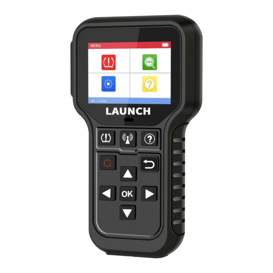
Page 24: Product Descriptions
LAUNCH 3. Product Descriptions 3.1 General Controls Name Notes Charging / Data I/O Connects the tool to computer via PORT charging/data cable for upgrade. www.x431.com +86 755 8455 7891... - Page 25 LAUNCH Insert the memory card into it to read or MEMORY CARD write the data/file stored in the memory SLOT card. BUTTON Press it to trigger the vehicle sensor. BUTTON Quick access to Help function. BUTTON Returns to previous menu.
-
Page 26: Specifications
LAUNCH Press it for about 3 seconds to turn it on. • Screen On: Press it once to enter hibernate mode. • If the tool is not charged and there is no operation made for the preset auto power-off interval, it will automatically power off. - Page 27 LAUNCH 6) User Manual 7) Sensors (Optional)
-
Page 28: Initial Use
LAUNCH 4. Initial Use 4.1 Charging & Turning On/Off 4.1.1 Charging There are three methods available for charging the tool. 1. Via AC outlet Connect one end of the charging cable to the charging port of the tool, and other end to the power adaptor. Plug the power adaptor into a AC outlet to start charging. -
Page 29: Main Menu
LAUNCH 4.2 Main Menu 4.2.1 Function modules The main menu screen includes the following function modules: Figure 4-1 Modules Descriptions This function allows you to perform the TPMS sensor TPMS activation, programming and relearning functions. This option presents a quick way to check for DTCs,... -
Page 30: Settings
LAUNCH Icon Descriptions The memory card is ejected or removed from the memory card slot. It appears when the tool is connected to the vehicle’s DLC port via the diagnostic cable. It appears when the tool is connected to the PC via the charging cable. - Page 31 LAUNCH 4) Datastream Units Set the measurement units of the datastream items (Metric or Imperial). 5) Auto Power Off This option enables you to set the time to turn off the tool automatically after not being operated. If the “Disable” option is selected, it will disable this auto power-off function.
-
Page 32: Tpms Operations
LAUNCH 5. TPMS Operations For initial use, please follow the flow chart below to start using it. Enter TPMS Select vehicle manufacturer Select vehicle model Select vehicle year Select the TPMS function (See *Note) Note: For indirect TPMS vehicle, only the Relearning function is supported. - Page 33 LAUNCH Figure 5-1 (Select MERCEDES) 2. Select B Class and press the OK button to enter the vehicle year selection screen. Figure 5-2 (Select B Class) 3. Select 2014~2018 and press the OK button to enter the TPMS function selection screen.
-
Page 34: Check Sensor
LAUNCH Figure 5-3 (Select 2014~2018) 4. Select 2014~2018 and press the OK button to enter the TPMS function selection screen. Figure 5-4 Note: For indirect TPMS vehicle, only the Learning function is supported. For vehicle using Direct TPMS, it generally includes: Activation, Programming and Relearning. - Page 35 LAUNCH 1. Select CHECK SENSOR and press the OK button to enter the following screen. Figure 5-5 2. For universal sensors, place the tool alongside the valve stem, point toward the sensor location, and press the button. Figure 5-6 Notes: 1.
- Page 36 LAUNCH Once the sensor is successfully activated and decoded, the tool will sound a beep and the screen will display the sensor data with a tick Figure 5-7 Notes: 1. The tool will do TPMS test in a sequence of FL (Front Left), FR (Front Right), RR (Rear Right), LR (Rear Left) and SPARE, if the vehicle has the option for the spare.
-
Page 37: Program Sensor
5.2 Program Sensor This function allows users to program the sensor data to the LAUNCH-sensor and replace faulty sensor with low battery life or one that is not functioning. The following options are available for programming LAUNCH-sensor: Auto Create, Manual Create, Copy ID by Activation and Create Multi-sensor (1-8). - Page 38 LAUNCH Figure 5-10 Press the OK button to start detecting the sensor and writing the new created sensor ID to the LAUNCH-sensor. Figure 5-11 A progress bar will appear on the screen indicating the programming process. www.x431.com +86 755 8455 7891...
-
Page 39: Manual Input
Press the continue programming other sensors. Note:If Auto Create is selected, the TPMS Relearn operation needs to be performed after programming all required LAUNCH-sensor. 5.2.2 Manual input This function allows users to manually enter sensor ID. Users can enter the random ID or the original sensor ID, if it is available. - Page 40 Note: Do not enter the same ID for each sensor. Select the wheel which needs to be programmed on the tool, place a LAUNCH-sensor close to the TPMS antenna of the tool. Press the OK button to start writing the new sensor ID to the LAUNCH-sensor.
- Page 41 2. If a vehicle does not support relearn function, please select the Manual Input option to enter the original sensor ID manually, or trigger the original sensor at the activation screen to get its information, before programming the LAUNCH- sensor.
-
Page 42: Copy Id By Activation
5.2.3 Copy ID by activation This function allows users to write in the retrieved original sensor data to the LAUNCH-sensor. It is used after the original sensor is triggered. Select COPY ID BY ACTIVATE and press the OK button to enter. - Page 43 LAUNCH Figure 5-22 Select the specific wheel position and press the OK button to create a sensor Figure 5-23 Press the OK button to start writing the new sensor ID to the LAUNCH-sensor.
-
Page 44: Program Multi-Sensor
LAUNCH Figure 5-24 After the sensor is successfully programmed, the following screen will appear. Figure 5-25 Press the button to return to the previous screen. Press the OK button to continue programming other sensors. 5.2.4 Program multi-sensor This function allows users to program multiple sensors simultaneously. Up to 8 sensors can be programmed at the same time. -
Page 45: Tpms Service
LAUNCH Figure 5-27 Press the button to return to the previous screen. Press the OK button to continue programming other sensors. 5.3 TPMS Service This function includes two modules: Relearn Procedure and Part Number Lookup. Select TPMS SERVICE and press the OK button to enter the following screen. -
Page 46: Part Number Lookup
LAUNCH sensor recognition. Figure 5-29 5.3.2 Part number lookup This function allows you to check the OE number of the sensors. www.x431.com +86 755 8455 7891... -
Page 47: Obd Diagnosing
LAUNCH 6. OBD Diagnosing This option presents a quick way to check for DTCs, isolate the cause of the illuminated Malfunction Indicator Lamp (MIL), check monitor status prior to emissions certification testing, verify repairs, and perform a number of other services that are emission-related. -
Page 48: Start Obd Diagnostics
LAUNCH Notes: • A plastic DLC cover may be found for some vehicles and you need to remove it before plugging the diagnostic cable. • The cable connector is keyed and will only fit one way. If you have problems... - Page 49 LAUNCH Figure 6-3 Press OK, the following screen will appear: Figure 6-4 It mainly includes the following functions: 1. Read Codes This function allows you to view the Diagnostic Trouble Codes (DTCs) retrieved from the vehicle’s on-board computer. Note: Never replace a part based only on the DTC definition. Each DTC has a set of testing procedures, instructions and flow charts that must be followed to confirm the location of the problem.
- Page 50 LAUNCH automatically read the SAE-standard DTCs and a screen similar to Figure 6-5 will appear. Figure 6-5 In Figure 6-3, • A - DTC: Displays the Diagnostic Trouble Code (DTC) number. Each fault is assigned a code number that is specific to that fault.
- Page 51 LAUNCH Note: In case the diagnostic codes are manufacturer-specific, users need to select the manufacturer manually and the following prompt message will appear on the screen. Figure 6-6 Press OK to enter to select the manufacturer. Figure 6-7 will be shown on the screen.
- Page 52 LAUNCH Figure 6-8 2. Erase Codes Note: When this function is used to erase DTCs from the vehicle’s on-board computer, “Freeze Frame” data is erased and “Permanent” DTCs ARE NOT erased. If you plan to take the vehicle to a Service Center for repair, DO NOT erase the codes from the vehicle’s computer.
- Page 53 LAUNCH Figure 6-9 Press OK to erase DTCs, and the following screen will appear: Figure 6-10 Follow the on-screen prompts to turn the ignition on with engine off, press OK to clear the DTCs. Note: When data is erased from the vehicle’s computer memory, the I/M Readiness Monitor Status program resets the status of all Monitors to a “Not...
- Page 54 LAUNCH a fault has been performed) to confirm that the repair has been performed correctly, and/or to check for Monitor Run Status. Select I/M Readiness from the Diagnostic Menu and press OK, the screen will display the I/M readiness result.
- Page 55 LAUNCH • Select View All Items and press OK, the screen will display the dynamic data of all data stream items: Figure 6-13 Press the button to turn page to view other data streams. Press to return to Diagnostic Menu.
- Page 56 LAUNCH • If View Graphic Items is selected in Data stream menu and press OK to enter the graphic items selection screen. button to select single data stream items, and press OK Press the button, the screen will display the selected items of live graphic data.
- Page 57 LAUNCH retrieve a list of information (provided by the vehicle manufacturer) from the vehicle’s on-board computer. This information may include: • VIN (Vehicle identification Number). It is applicable to model year 2000 and newer OBD II-compliant vehicles. • CID (Calibration ID). These IDs uniquely identify the software version(s) for the vehicle’s control module(s).
-
Page 58: Help
LAUNCH 7. Help This menu enables you to view device information and OBD introduction. and press OK to enter the following On the main menu screen, select screen. Figure 7-1 7.1 DLC Location Information This option helps you to find the location of the vehicle’s DLC. -
Page 59: Library Version
LAUNCH Note: You are strongly recommended to note down the Serial Number and Register Code in Figure 7-2 since these 2 pieces of information are required while registering your tool. Press to return to the previous screen. 7.3 Library Version This option allows you to view the database and relearn procedure version. -
Page 60: Register & Update
LAUNCH 8. Register & Update Prerequisite conditions: 1. Go to http://www.x431.com/CRT511 to download the update tool and install it on the computer. 2. System requirements: Windows XP, 7, 8 or Windows 10. The tool can be updated via memory card. - Page 61 For better experience, it is recommended to register and upgrade the tool first. But if not, the tool can also be used normally. 1). Launch the update tool, the following screen will appear: Figure 8-3 2). Select the target language and enter the Serial Number, click Device Upgrade, the following screen will appear.
- Page 62 LAUNCH Note: For initial update, user needs to go through a registration process. Once you finished it, the registration screen will not appear again each time you click the Device Upgrade button in the future. 3. Copy the update package into the memory card.
-
Page 63: Faq
LAUNCH 9. FAQ Here we list some frequently asked questions and answers relating to this tool. Question: System halts when reading data stream. What is the reason? Answer: It may be caused by a slackened connector. Please turn off the tool, firmly connect the connector, and switch it on again. - Page 64 The exclusive remedy for any automotive meter found to be defective is repair or replacement, and LAUNCH shall not be liable for any consequential or incidental damages.
Need help?
Do you have a question about the CRT5011E and is the answer not in the manual?
Questions and answers
Здравствуйте. В руководстве нет списка автомобилей который может диагностировать прибор по протоколу OBD2