Advertisement
Do you have a question about the Creader Professional 129i and is the answer not in the manual?
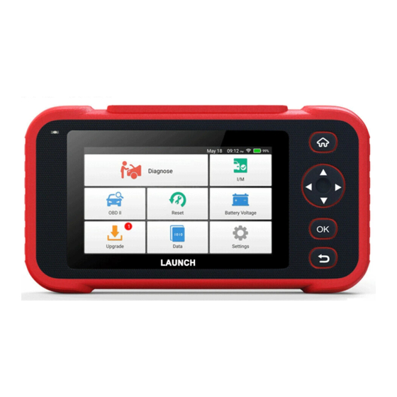
Does the scan tool work with international trucks


Need help?
Do you have a question about the Creader Professional 129i and is the answer not in the manual?
Questions and answers
Does the scan tool work with international trucks